fuse Hyundai Atos 2002 User Guide
[x] Cancel search | Manufacturer: HYUNDAI, Model Year: 2002, Model line: Atos, Model: Hyundai Atos 2002Pages: 249, PDF Size: 3.11 MB
Page 202 of 249

3-1
WHAT TO DO IN AN EMERGENCY
fitted with automatic transaxle ensure that the transaxle selector is at the "P" or"N"position.
2. Check the battery terminals and connec- tions to ensure that these are clean and alsotight.
3. If the ignition warning lamps dim when the engine is cranked and the battery terminalshave been checked, a discharged battery isindicated.
4. Do not attempt to push or tow start the vehicle, refer to "Jump Starting" for informa-tion regarding engine starting when the bat-tery is discharged.
DD020A1-E
IF THE ENGINE WILL NOT START Seek assistance from the nearest Hyundai
dealer with regard to the method of ignition andfuel system diagnosis.
CAUTION: If the engine refuses to start, no attempt
should be made to push or tow start the vehicle. Vehicles with automatic transaxleor fuel injection will not be able to be startedin this manner since no drive is transmittedthrough the automatic transaxle whilst theengine is not running, and in the case of fuelinjected derivatives, the fuel pump will notoperate under tow start conditions. In addi-tion, if the vehicle is equipped with an ex-haust catalyst, damage to the catalyst mayresult if the vehicle is tow started. ZD000A1-E
3. WHAT TO DO IN AN
EMERGENCY
DD020B1-E
IF THE ENGINE CANNOT BE
CRANKED
1. If the vehicle is fitted with manual transaxle ensure that the clutch pedal is depressedwhilst cranking the engine. If the vehicle is ZD020C2-D
If Engine Turns Over Normally but Does Not Start AD020D1-A
If Engine Stalls While Driving
1. Reduce your speed gradually, keeping a straight line. Move cautiously off the road to a safe place.
2. Turn on your emergency flashers.
3. Try starting the engine again. If your vehicle will not start, see “IF THE ENGINE WILL NOT START”
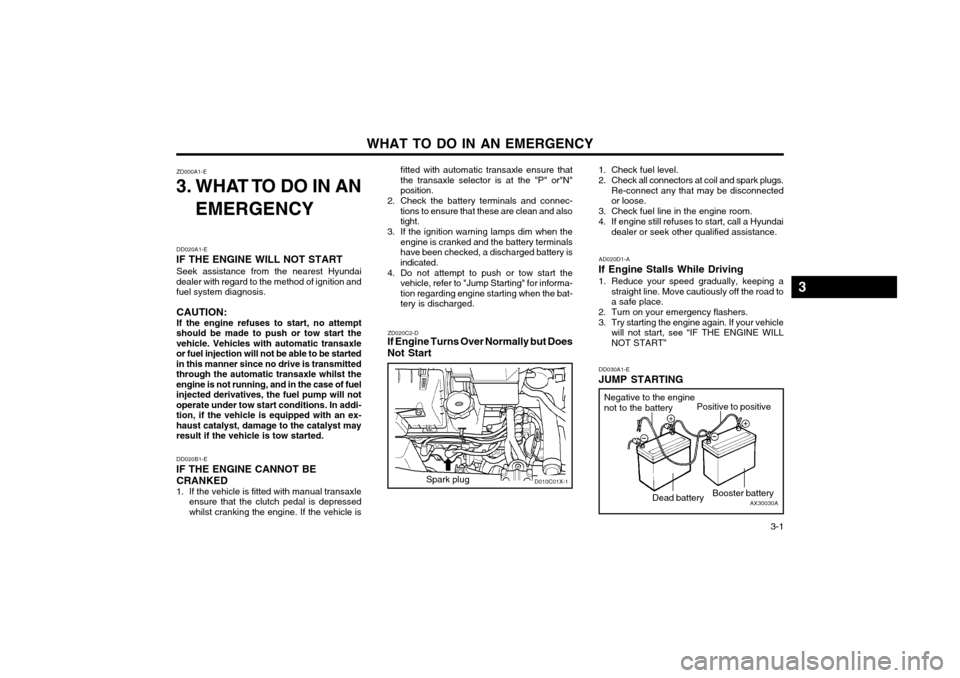
DD030A1-E
JUMP STARTING
1. Check fuel level.
2. Check all connectors at coil and spark plugs.
Re-connect any that may be disconnected or loose.
3. Check fuel line in the engine room.
4. If engine still refuses to start, call a Hyundai dealer or seek other qualified assistance.
AX30030A
Negative to the enginenot to the battery
Positive to positive
Dead battery Booster battery
D010C01X-1Spark plug
3
Page 232 of 249

DO-IT-YOURSELF MAINTENANCE
6-14 AG200A1-A
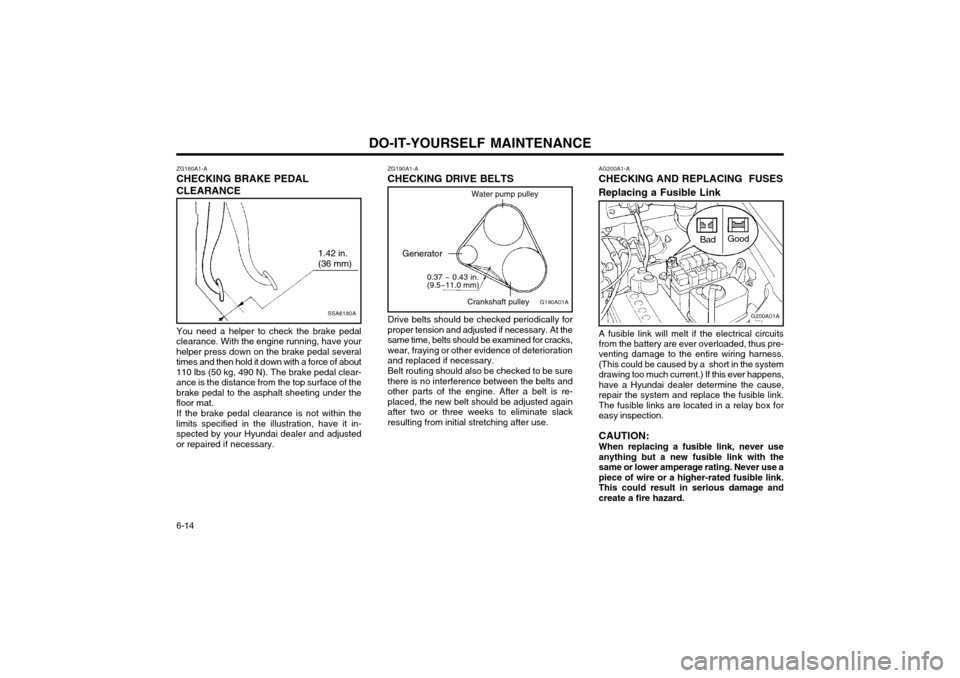
CHECKING AND REPLACING FUSES Replacing a Fusible Link
G200A01A
Bad
Good
A fusible link will melt if the electrical circuits from the battery are ever overloaded, thus pre- venting damage to the entire wiring harness.(This could be caused by a short in the systemdrawing too much current.) If this ever happens,have a Hyundai dealer determine the cause,repair the system and replace the fusible link.The fusible links are located in a relay box foreasy inspection. CAUTION: When replacing a fusible link, never use anything but a new fusible link with thesame or lower amperage rating. Never use apiece of wire or a higher-rated fusible link.This could result in serious damage andcreate a fire hazard.
ZG190A1-A
CHECKING DRIVE BELTS
G190A01A
Water pump pulley
Generator 0.37 ~ 0.43 in. (9.5~11.0 mm) Crankshaft pulley
Drive belts should be checked periodically for proper tension and adjusted if necessary. At thesame time, belts should be examined for cracks,wear, fraying or other evidence of deteriorationand replaced if necessary. Belt routing should also be checked to be sure there is no interference between the belts andother parts of the engine. After a belt is re-placed, the new belt should be adjusted againafter two or three weeks to eliminate slackresulting from initial stretching after use.
ZG180A1-A
CHECKING BRAKE PEDAL CLEARANCE
SSA6180A
1.42 in. (36 mm)
You need a helper to check the brake pedal
clearance. With the engine running, have your helper press down on the brake pedal severaltimes and then hold it down with a force of about110 lbs (50 kg, 490 N). The brake pedal clear-ance is the distance from the top surface of thebrake pedal to the asphalt sheeting under thefloor mat.
If the brake pedal clearance is not within the
limits specified in the illustration, have it in-spected by your Hyundai dealer and adjustedor repaired if necessary.
Page 233 of 249

DO-IT-YOURSELF MAINTENANCE 6-15
DG200B2-E
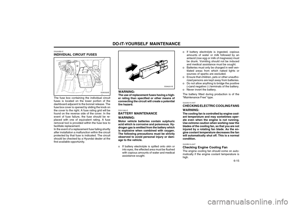
INDIVIDUAL CIRCUIT FUSES
XV60320E
The fuse box containing the individual circuit fuses is located on the lower portion of thedashboard adjacent to the bonnet release. Thefuse box cover is opened by sliding the knob onthe cover to the right. A fuse rating grid will befound on the reverse side of the cover. In theevent of fuse failure, the fuse should be re-placed with one of equivalent rating. A fuseremoval tool is provided within the fuse box tofacilitate replacement. In the event of a replacement fuse failing shortly after installation a malfunction within the circuitprotected by that fuse is indicated. The circuitshould be checked by a Hyundai dealer at thefirst available opportunity.
SSA6201B
WARNING: The use of replacement fuses having a high-
er rating than specified or other means of connecting the circuit will create a potentialfire hazard.
DG210A2-E
BATTERY MAINTENANCE WARNING:
Motor vehicle batteries contain sulphuric
acid which is corrosive and poisonous. Hy- drogen gas is emitted from the battery whichis explosive when combined with oxygen.The following precautions must be strictlyobserved to avoid personal injury or dam-age to the vehicle.
o If battery electrolyte is spilled onto skin or into eyes, the effected area must be flushed with copious amounts of water and medicalassistance sought. o If battery electrolyte is ingested, copious
amounts of water or milk followed by anantacid (raw egg or milk of magnesia) mustbe drunk. Vomiting should not be inducedand medical assistance must be sought.
o Batteries must only be charged in well ven- tilated areas from which naked lights orsources of sparks are excluded.
o Ensure that children, pets or other unautho- rized persons are kept away from batteries.
o Do not allow anything to bridge the positive (+)and negative (-) terminals of the battery.
o Never invert the battery.
The battery fitted during production is of the“Maintenance Free” type. G220A01A-AAT
CHECKING ELECTRIC COOLING FANS WARNING:
The cooling fan is controlled by engine cool- ant temperature and may sometimes oper-ate even when the engine is not running.
Use extreme caution when working near theblades of the cooling fan, so that you are notinjured by a rotating fan blade. As the en-
gine coolant temperature decreases the fanwill automatically shut off. This is a normalcondition. G220B01A-AAT
Checking Engine Cooling Fan The engine cooling fan should come on auto- matically if the engine coolant temperature ishigh.
Page 248 of 249

INDEX
10-2
FRONT FOG LIGHT
SWITCH ......................................................... 1-29
FUEL ECONOMY ............................................................................... 2-3
FUEL GAUGE .................................................................................. 1-20
FUEL RECOMMENDATIONS ........... ................................................. 1-1
FUSIBLE LINKS ............................................................................... 6-14
G GENERAL CHECKS .......................................................................... 6-2
H
HAZARD WARNING SYSTEM ........................................................ 1-24
HEADLIGHT BULB ........................................................................... 6-16
HEADLIGHT LEVELING DEVICE SYSTEM ....................................1-23
HEADRESTRAINT .............................................................................. 1-5
HEADLIGHT FLASH ER .................................................................... 1-22
HEADLIGHT SWITCH ...................................................................... 1-21
HEATED REAR WINDOW ................... ............................................1-24
HEATING AND VENTILATION ........................................................ 1-32
HIGH AND LOW BEAM ................................................................... 1-21
HIGH-MOUNTED REAR STOPLIGHT .............................................1-27
HORN ............................................................................................... 1-32
IIF THE ENGINE CANNOT BE CRANKED ........................................ 3-1
IF THE ENGINE OVERHEATS .......................................................... 3-2
IF THE ENGINE WILL NOT START .................................................. 3-1
IGNITION SWITCH ............................................................................. 2-2
IMMOBILIZER SYSTEM ..................................................................... 1-2INDIVIDUAL CIRCUIT FUSES ......................................................... 6-15
INSTRUMENT CLUSTER AND INDICATOR ..................................1-17INSTRUMENTS AND CONTROLS
..................................................1-16
INTERIOR LIGHT ............................................................................. 1-25
JJUMP STARTI NG ........................................................................ 3-1~3-2
KKEY POSITIONS ................................................................................ 2-2
KEYS .................................................................................................. 1-2 L LIGHT BULBS .................................................................................. 6-16
LIMP HOME PROCEDURES ............................................................. 1-2
LOW FUEL LEVEL WARNING LAMP .............................................1-19
M
MAINTENANCE AND SERVICING REQUIREMENTS ..................... 5-1
MAINTENANCE UNDER SEVERE USAGE CONDITIONS .............. 5-4
MANUAL TRANSAXLE LUBRICANT ................................................. 6-9
MANUAL TRANSAXLE ...................................................................... 2-4
MULTI FUNCTION SWITCH ................................. ...........................1-21
OODOMETER ..................................................................................... 1-21
OIL PRESSURE WARNING LIGHT ................................................. 1-18
OUTSIDE REAR VIEW MIRROR ....................................................1-25
PPARKING BRAKE ............................................................................ 1-26
POWER STEERING FLUID LEVEL ................................................. 6-16