fuse Hyundai Atos 2002 Owner's Manual
[x] Cancel search | Manufacturer: HYUNDAI, Model Year: 2002, Model line: Atos, Model: Hyundai Atos 2002Pages: 249, PDF Size: 3.11 MB
Page 25 of 249
FEATURES OF YOUR HYUNDAI
FEATURES OF YOUR HYUNDAI FEATURES OF YOUR HYUNDAI
FEATURES OF YOUR HYUNDAI
FEATURES OF YOUR HYUNDAI
1- 16 to the body structure, can adversely affect SRS performance and lead to possibleinjury.
o For cleaning the airbag pad covers, use only a soft, dry cloth or one which hasbeen moistened with plain water. Solventsor cleaners could adversely affect theairbag covers and proper deployment ofthe system.
o No objects should be placed over or near the airbag modules on the steering wheel,instrument panel, and the front passen-ger's panel above the glove box, becauseany such object could cause harm if thevehicle is in a crash severe enough tocause the airbags to inflate.
o If the airbags inflate, they must be re- placed by an authorized Hyundai dealer.
o Do not tamper with or disconnect SRS wiring, or other components of the SRSsystem. Doing so could result in injury,due to accidental firing of the airbags orby rendering the SRS inoperative.
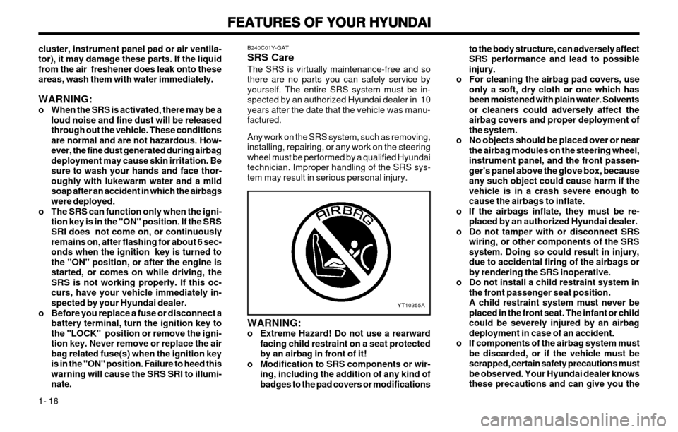
o Do not install a child restraint system in the front passenger seat position.A child restraint system must never beplaced in the front seat. The infant or childcould be severely injured by an airbagdeployment in case of an accident.
o If components of the airbag system must be discarded, or if the vehicle must bescrapped, certain safety precautions mustbe observed. Your Hyundai dealer knowsthese precautions and can give you the
YT10355A
cluster, instrument panel pad or air ventila- tor), it may damage these parts. If the liquidfrom the air freshener does leak onto theseareas, wash them with water immediately. WARNING:
o When the SRS is activated, there may be a loud noise and fine dust will be released through out the vehicle. These conditionsare normal and are not hazardous. How-ever, the fine dust generated during airbagdeployment may cause skin irritation. Besure to wash your hands and face thor-oughly with lukewarm water and a mildsoap after an accident in which the airbagswere deployed.
o The SRS can function only when the igni- tion key is in the "ON" position. If the SRSSRI does not come on, or continuouslyremains on, after flashing for about 6 sec-onds when the ignition key is turned tothe "ON" position, or after the engine isstarted, or comes on while driving, theSRS is not working properly. If this oc-curs, have your vehicle immediately in-spected by your Hyundai dealer.
o Before you replace a fuse or disconnect a battery terminal, turn the ignition key tothe "LOCK" position or remove the igni-tion key. Never remove or replace the airbag related fuse(s) when the ignition keyis in the "ON" position. Failure to heed thiswarning will cause the SRS SRI to illumi-nate. B240C01Y-GAT SRS CareThe SRS is virtually maintenance-free and so there are no parts you can safely service byyourself. The entire SRS system must be in-spected by an authorized Hyundai dealer in 10years after the date that the vehicle was manu-factured. Any work on the SRS system, such as removing, installing, repairing, or any work on the steeringwheel must be performed by a qualified Hyundaitechnician. Improper handling of the SRS sys-tem may result in serious personal injury. WARNING:
o Extreme Hazard! Do not use a rearward
facing child restraint on a seat protectedby an airbag in front of it!
o Modification to SRS components or wir- ing, including the addition of any kind ofbadges to the pad covers or modifications
Page 32 of 249
FEATURES OF YOUR HYUNDAI
FEATURES OF YOUR HYUNDAI FEATURES OF YOUR HYUNDAI
FEATURES OF YOUR HYUNDAI
FEATURES OF YOUR HYUNDAI
1- 23
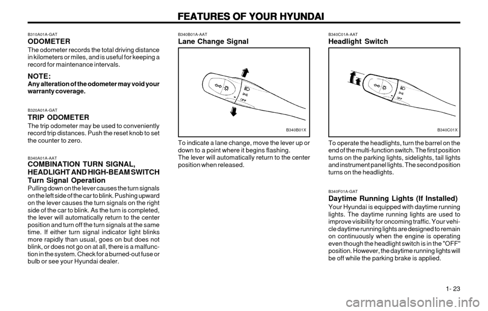
B340B01A-AAT Lane Change Signal To indicate a lane change, move the lever up or down to a point where it begins flashing.The lever will automatically return to the centerposition when released.
B340A01A-AAT COMBINATION TURN SIGNAL, HEADLIGHT AND HIGH-BEAM SWITCH Turn Signal Operation Pulling down on the lever causes the turn signals on the left side of the car to blink. Pushing upwardon the lever causes the turn signals on the rightside of the car to blink. As the turn is completed,the lever will automatically return to the centerposition and turn off the turn signals at the sametime. If either turn signal indicator light blinksmore rapidly than usual, goes on but does notblink, or does not go on at all, there is a malfunc-tion in the system. Check for a burned-out fuse orbulb or see your Hyundai dealer.
B340B01X
B310A01A-GAT ODOMETERThe odometer records the total driving distance in kilometers or miles, and is useful for keeping arecord for maintenance intervals. NOTE: Any alteration of the odometer may void yourwarranty coverage. B320A01A-GAT TRIP ODOMETER The trip odometer may be used to conveniently record trip distances. Push the reset knob to setthe counter to zero. B340C01A-AAT Headlight Switch To operate the headlights, turn the barrel on the end of the multi-function switch. The first positionturns on the parking lights, sidelights, tail lightsand instrument panel lights. The second positionturns on the headlights.
B340C01X
B340F01A-GAT Daytime Running Lights (If Installed) Your Hyundai is equipped with daytime running lights. The daytime running lights are used toimprove visibility for oncoming traffic. Your vehi-cle daytime running lights are designed to remainon continuously when the engine is operatingeven though the headlight switch is in the "OFF"position. However, the daytime running lights willbe off while the parking brake is applied.
Page 59 of 249
FEATURES OF YOUR HYUNDAI
FEATURES OF YOUR HYUNDAI FEATURES OF YOUR HYUNDAI
FEATURES OF YOUR HYUNDAI
FEATURES OF YOUR HYUNDAI
1- 50
B922F01X-GAT 1. STOP
o Insert the CD to start CD playback, during the
radio operation.
o Press the button to stop CD playback and to change the source to the radio.
2. FF/REWWhile the disc is playing, press and hold FF button to quickly move forward until you reachthe desired section of the track and vice versa. 3. TRACK UP/DOWN
o The desired track on the disc currently being played can be selected using the track num- ber.
o Pressing the button once increases the track number by one and pressing the button decreases it.
4. REPEAT
o To repeat the music you are listening to, press the RPT button and to cancel music repeat, press again.
FM/AM
5. EJECT Button When the EJECT button is pressed with the CD loaded, the CD is ejected. NOTE:
o To ensure proper operation of the unit,keep the vehicle interior temperature with-in a normal range by using the vehicle's airconditioning or heating system.
o When replacing the fuse, replace it with a fuse having the correct capacity.
o The preset station frequencies are all erased when the car battery is discon-nected. Therefore, all data will have to beset again if this should occur.
o Do not add any oil to the rotating parts.
o This equipment is designed to be used only in a 12 volt DC battery system withnegative ground.
o This unit is made of precision parts. Do not attempt to disassemble or adjust anyparts.
o When driving your vehicle, be sure to keep the volume of the unit set low enough toallow you to hear sounds coming from theoutside.
o Do not expose this equipment (including the speakers and tape) to water or exces-sive moisture.
Page 78 of 249
WHAT TO DO IN AN EMERGENCY
WHAT TO DO IN AN EMERGENCY WHAT TO DO IN AN EMERGENCY
WHAT TO DO IN AN EMERGENCY
WHAT TO DO IN AN EMERGENCY
3-1
D010B01A-AATIf Engine Doesn't Turn Over or Turns
If Engine Doesn't Turn Over or Turns If Engine Doesn't Turn Over or Turns
If Engine Doesn't Turn Over or Turns
If Engine Doesn't Turn Over or Turns
Over Slowly
Over Slowly Over Slowly
Over Slowly
Over Slowly 3.3.
3.3.
3.
WHA
WHA WHA
WHA
WHA
T
T T
T
T
TT
TT
T
O DO IN AN
O DO IN AN O DO IN AN
O DO IN AN
O DO IN AN
EMERGENCY
EMERGENCY EMERGENCY
EMERGENCY
EMERGENCY
D010A01A-AAT IF THE ENGINE WILL NOT START
IF THE ENGINE WILL NOT START IF THE ENGINE WILL NOT START
IF THE ENGINE WILL NOT START
IF THE ENGINE WILL NOT START
CAUTION:
CAUTION: CAUTION:
CAUTION:
CAUTION:
If the engine will not start, do not push or
If the engine will not start, do not push or If the engine will not start, do not push or
If the engine will not start, do not push or
If the engine will not start, do not push or pull the car to
pull the car to pull the car to
pull the car to
pull the car to start it. This could result in a
start it. This could result in a start it. This could result in a
start it. This could result in a
start it. This could result in a
collision or cause other damage. In addi-
collision or cause other damage. In addi- collision or cause other damage. In addi-
collision or cause other damage. In addi-
collision or cause other damage. In addi-
tion,
tion, tion,
tion,
tion, push or pull starting may cause the
push or pull starting may cause the push or pull starting may cause the
push or pull starting may cause the
push or pull starting may cause the
catalytic converter to be overloaded and
catalytic converter to be overloaded and catalytic converter to be overloaded and
catalytic converter to be overloaded and
catalytic converter to be overloaded and
create a fire hazard.
create a fire hazard. create a fire hazard.
create a fire hazard.
create a fire hazard. 1. If your car has an automatic transaxle, be
sure the gear selector lever is in "N" or "P" and the emergency brake is set.
2. Check the battery connections to be sure they are clean and tight.
3. Turn on the interior light. If the light dims or goes out when you operate the starter, thebattery is discharged.
4. Check the starter connections to be sure they are securely tightened.
5. Do not push or pull the vehicle to start it. See instructions for "Jump Starting" on the fol-lowing pages.
D010C01A-AAT If Engine Turns Over Normally but Does
If Engine Turns Over Normally but Does If Engine Turns Over Normally but Does
If Engine Turns Over Normally but Does
If Engine Turns Over Normally but Does
Not Start
Not Start Not Start
Not Start
Not Start
1. Check fuel level.
2. Check all connectors at ignition, coil and
spark plugs. Reconnect any that may be disconnected or loose. D010D01A-AAT
If the Engine Stalls While Driving
If the Engine Stalls While Driving If the Engine Stalls While Driving
If the Engine Stalls While Driving
If the Engine Stalls While Driving
1. Reduce your speed gradually, keeping a
straight line. Move cautiously off the road to a safe place.
2. Turn on your emergency flashers.
3. Try to start the engine again. If your vehicle will not start, contact a Hyundai dealer or seek other qualified assistance.
D010B01A
3. Check the fuel line in the engine room.
4. If the engine still refuses to start, call aHyundai dealer or seek other qualified as- sistance.
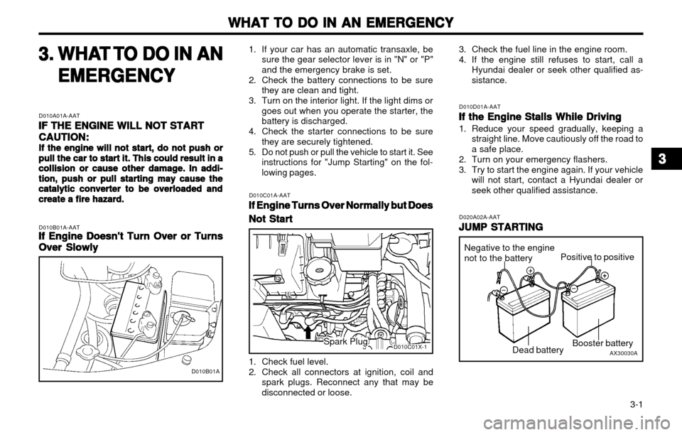
D020A02A-AAT JUMP STARTING
JUMP STARTING JUMP STARTING
JUMP STARTING
JUMP STARTING
AX30030A
Negative to the engine not to the battery
Booster battery
Positive to positive
Dead battery
D010C01X-1Spark Plug
33
33
3
Page 110 of 249
DO-IT-YOURSELF MAINTENANCE
DO-IT-YOURSELF MAINTENANCE DO-IT-YOURSELF MAINTENANCE
DO-IT-YOURSELF MAINTENANCE
DO-IT-YOURSELF MAINTENANCE
6-14 G200A01A-AAT
CHECKING AND REPLACING
CHECKING AND REPLACING CHECKING AND REPLACING
CHECKING AND REPLACING
CHECKING AND REPLACING
FUSES
FUSES FUSES
FUSES
FUSES
Replacing a Fusible Link
Replacing a Fusible Link Replacing a Fusible Link
Replacing a Fusible Link
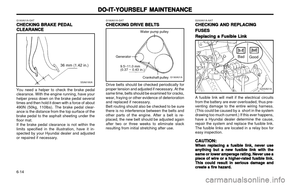
Replacing a Fusible Link A fusible link will melt if the electrical circuits from the battery are ever overloaded, thus pre-venting damage to the entire wiring harness.(This could be caused by a short in the systemdrawing too much current.) If this ever happens,have a Hyundai dealer determine the cause,repair the system and replace the fusible link.The fusible links are located in a relay box foreasy inspection.
CAUTION:
CAUTION: CAUTION:
CAUTION:
CAUTION:
When replacing a fusible link, never use
When replacing a fusible link, never use When replacing a fusible link, never use
When replacing a fusible link, never use
When replacing a fusible link, never use
anything but a new fusible link with the
anything but a new fusible link with the anything but a new fusible link with the
anything but a new fusible link with the
anything but a new fusible link with the
same or lower amperage rating. Never use a
same or lower amperage rating. Never use a same or lower amperage rating. Never use a
same or lower amperage rating. Never use a
same or lower amperage rating. Never use a
piece of wire or a higher-rated fusible link.
piece of wire or a higher-rated fusible link. piece of wire or a higher-rated fusible link.
piece of wire or a higher-rated fusible link.
piece of wire or a higher-rated fusible link.
This could result in serious damage and
This could result in serious damage and This could result in serious damage and
This could result in serious damage and
This could result in serious damage and
create a fire hazard.
create a fire hazard. create a fire hazard.
create a fire hazard.
create a fire hazard.
G200A01A
Bad
Good
G180A01A-GAT
CHECKING BRAKE PEDAL
CHECKING BRAKE PEDAL CHECKING BRAKE PEDAL
CHECKING BRAKE PEDAL
CHECKING BRAKE PEDAL
CLEARANCE
CLEARANCE CLEARANCE
CLEARANCE
CLEARANCE
SSA6180A
36 mm (1.42 in.)
You need a helper to check the brake pedal clearance. With the engine running, have yourhelper press down on the brake pedal severaltimes and then hold it down with a force of about490N (50kg, 110lbs). The brake pedal clear-ance is the distance from the top surface of thebrake pedal to the asphalt sheeting under thefloor mat. If the brake pedal clearance is not within the limits specified in the illustration, have it in-spected by your Hyundai dealer and adjustedor repaired if necessary.
G190A01A-GAT CHECKING DRIVE BELTS
CHECKING DRIVE BELTS CHECKING DRIVE BELTS
CHECKING DRIVE BELTS
CHECKING DRIVE BELTS
Water pump pulley
Crankshaft pulley
Drive belts should be checked periodically for
proper tension and adjusted if necessary. At the same time, belts should be examined for cracks,wear, fraying or other evidence of deteriorationand replaced if necessary. Belt routing should also be checked to be sure
there is no interference between the belts andother parts of the engine. After a belt is re-placed, the new belt should be adjusted againafter two or three weeks to eliminate slackresulting from initial stretching after use.
G190A01A
9.5~11.0 mm (0.37 ~ 0.43 in.)
Generator
Page 111 of 249
DO-IT-YOURSELF MAINTENANCE
DO-IT-YOURSELF MAINTENANCE DO-IT-YOURSELF MAINTENANCE
DO-IT-YOURSELF MAINTENANCE
DO-IT-YOURSELF MAINTENANCE
6-15
CAUTION:
CAUTION: CAUTION:
CAUTION:
CAUTION:
A burned-out fuse indicates that there is a
A burned-out fuse indicates that there is a A burned-out fuse indicates that there is a
A burned-out fuse indicates that there is a
A burned-out fuse indicates that there is a problem in the electrical circuit. If you re-
problem in the electrical circuit. If you re- problem in the electrical circuit. If you re-
problem in the electrical circuit. If you re-
problem in the electrical circuit. If you re-
place a fuse and it blows as soon as the
place a fuse and it blows as soon as the place a fuse and it blows as soon as the
place a fuse and it blows as soon as the
place a fuse and it blows as soon as the
accessory is turned on, the problem is seri-
accessory is turned on, the problem is seri- accessory is turned on, the problem is seri-
accessory is turned on, the problem is seri-
accessory is turned on, the problem is seri-
ous and should be referred to a Hyundai
ous and should be referred to a Hyundai ous and should be referred to a Hyundai
ous and should be referred to a Hyundai
ous and should be referred to a Hyundai
dealer for diagnosis and repair. Never re-
dealer for diagnosis and repair. Never re- dealer for diagnosis and repair. Never re-
dealer for diagnosis and repair. Never re-
dealer for diagnosis and repair. Never re-
place a fuse with anything except a fuse
place a fuse with anything except a fuse place a fuse with anything except a fuse
place a fuse with anything except a fuse
place a fuse with anything except a fuse
with the same or a lower amperage rating. A
with the same or a lower amperage rating. A with the same or a lower amperage rating. A
with the same or a lower amperage rating. A
with the same or a lower amperage rating. A
higher capacity fuse could cause damage
higher capacity fuse could cause damage higher capacity fuse could cause damage
higher capacity fuse could cause damage
higher capacity fuse could cause damage
and create a fire hazard.
and create a fire hazard. and create a fire hazard.
and create a fire hazard.
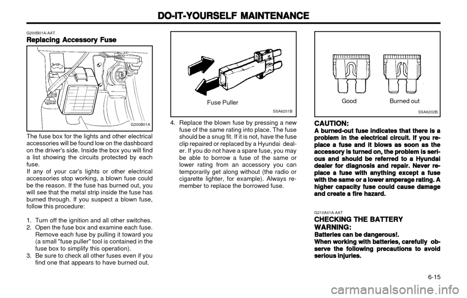
and create a fire hazard. Good
Burned out
4. Replace the blown fuse by pressing a new fuse of the same rating into place. The fuse should be a snug fit. If it is not, have the fuseclip repaired or replaced by a Hyundai deal-er. If you do not have a spare fuse, you maybe able to borrow a fuse of the same orlower rating from an accessory you cantemporarily get along without (the radio orcigarette lighter, for example). Always re-member to replace the borrowed fuse.
G200B01A-AAT
Replacing Accessory Fuse
Replacing Accessory Fuse Replacing Accessory Fuse
Replacing Accessory Fuse
Replacing Accessory Fuse
The fuse box for the lights and other electrical
accessories will be found low on the dashboardon the driver's side. Inside the box you will finda list showing the circuits protected by eachfuse.
If any of your car's lights or other electrical
accessories stop working, a blown fuse couldbe the reason. If the fuse has burned out, youwill see that the metal strip inside the fuse hasburned through. If you suspect a blown fuse,follow this procedure:
1. Turn off the ignition and all other switches.
2. Open the fuse box and examine each fuse. Remove each fuse by pulling it toward you (a small "fuse puller" tool is contained in thefuse box to simplify this operation).
3. Be sure to check all other fuses even if you find one that appears to have burned out.
G200B01A
SSA6201BSSA6202B
Fuse Puller
G210A01A-AATCHECKING THE BATTERY
CHECKING THE BATTERY CHECKING THE BATTERY
CHECKING THE BATTERY
CHECKING THE BATTERY
WARNING:
WARNING: WARNING:
WARNING:
WARNING:
Batteries can be dangerous!.
Batteries can be dangerous!. Batteries can be dangerous!.
Batteries can be dangerous!.
Batteries can be dangerous!.
When working with batteries, carefully ob-
When working with batteries, carefully ob- When working with batteries, carefully ob-
When working with batteries, carefully ob-
When working with batteries, carefully ob-
serve the following precautions to avoid
serve the following precautions to avoid serve the following precautions to avoid
serve the following precautions to avoid
serve the following precautions to avoid
serious injuries.
serious injuries. serious injuries.
serious injuries.
serious injuries.
Page 126 of 249
INDEX
INDEX INDEX
INDEX
INDEX
10-2 EE
EE
E
Emission Control System ................................................................... 7-1Engine
Before starting the engine .............................................................. 2-2
Compartment (For MFI) ................................................................. 6-1 Coolant ........................................................................................... 6-5
Coolant temperature gauge ......................................................... 1-22
If the engine overheats .................................................................. 3-2 Number .......................................................................................... 8-1
Oil .................................................................................................. 6-2
Oil consumption ............................................................................. 6-3
Starting ........................................................................................... 2-3
Engine Exhaust Can Be Dangerous ................................................... 2-1
FF
FF
F
Fan Speed Control ............................................................................ 1-34
Fog Light
Front ............................................................................................. 1-31
Rear ............................................................................................. 1-31
Front Seats Adjustable front seats .................................................................... 1-5
Adjustable headrests ..................................................................... 1-6
Adjusting seat forward and rearward ............................................. 1-5
Adjusting seatback angle ............................................................... 1-6
Fuel Capacity ......................................................................................... 9-1Gauge .......................................................................................... 1-22
Recommendations ......................................................................... 1-1 Fuel Filler Lid
Remote release ............................................................................ 1-31
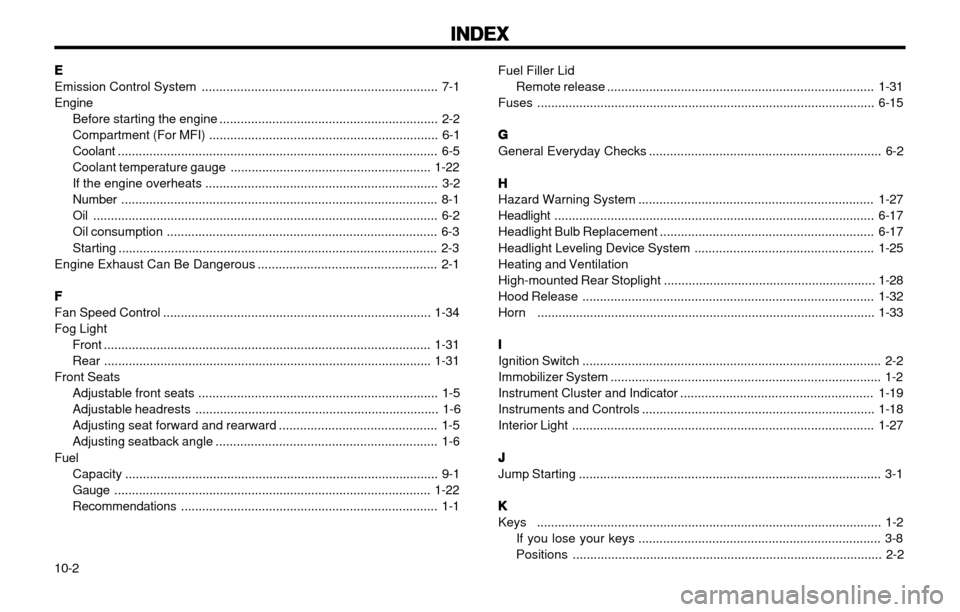
Fuses ................................................................................................ 6-15
GG
GG
G
General Everyday Checks .................................................................. 6-2
HH
HH
H
Hazard Warning System ................................................................... 1-27
Headlight ........................................................................................... 6-17
Headlight Bulb Replacement ............................................................. 6-17
Headlight Leveling Device System ................................................... 1-25
Heating and Ventilation
High-mounted Rear Stoplight ............................................................ 1-28
Hood Release ................................................................................... 1-32
Horn ................................................................................................ 1-33
II
II
I
Ignition Switch ..................................................................................... 2-2
Immobilizer System ............................................................................. 1-2
Instrument Cluster and Indicator ....................................................... 1-19
Instruments and Controls .................................................................. 1-18
Interior Light ...................................................................................... 1-27
JJ
JJ
J
Jump Starting ...................................................................................... 3-1
KK
KK
K
Keys .................................................................................................. 1-2
If you lose your keys ..................................................................... 3-8
Positions ........................................................................................ 2-2
Page 151 of 249
FEATURES OF YOUR HYUNDAI
1-14 B240C01X-EAT SRS CareThe SRS is virtually maintenance-free and so there are no parts you can safely service byyourself. The entire SRS system must be in-spected by an authorized Hyundai dealer in 10years after the date that the car was manufac-ture. Any work on the airbag system, such as remov- ing, installing, repairing, or any work on thesteering wheel must be performed by a quali-fied Hyundai technician. Improper handling of the airbag system may result in serious personal injury. WARNING:
o Modification to SRS components or wir- ing, including the addition of any kind of badges to the pad cover or modifica-tions to the body structure, can adverse-ly affect SRS performance and lead topossible injury.
o For cleaning the horn pad, use only a soft, dry cloth or one which has beenmoistened with plain water. Solvents orcleaners could adversely affect the airbagcover and proper deployment of the sys-tem.
o No objects should be placed over or near the label identifying the airbag on thesteering wheel and instrument panel,because any such object could causeharm if the vehicle is in a crash severeenough to cause the airbag to inflate.
WARNING:
o When the SRS is activated, there may be
a loud noise and fine dust will be re- leased through out the vehicle. Theseconditions are normal and are not haz-ardous. However, the fine dust generat-ed during airbag deployment may causeskin irritation. Be sure to wash your handsand face thoroughly with lukewarm wa-ter and a mild soap after an accident inwhich the airbags were deployed.
o The SRS can function only when the ignition key is in the "ON" position. If theSRS SRI does not come on, or continu-ously remains on, after flashing for about6 seconds when the ignition key is turnedto the "ON" position, or after the engineis started, or comes on while driving, theSRS is not working properly. If this oc-curs, have your vehicle immediately in-spected by your Hyundai dealer.
o Before you replace a fuse or disconnect a battery terminal, turn the ignition key tothe "LOCK" position or remove the igni-tion key. Never remove or replace the airbag related fuse(s) when the ignition keyis in the "ON" position. Failure to heedthis warning will cause the SRS SRI toilluminate.
Upon deployment, tear seams molded directly
into the pad covers will separate under pres-sure from the expansion of the airbags. Furtheropening of the covers then allows full inflation ofthe airbags.
A fully inflated airbag in combination with a
properly worn seat belt slows the driver's for-ward motion, thus reducing the
risk of head and chest injury. After complete inflation, the airbag immediately
starts deflating, enabling the driver to maintain forward visibility.
CAUTION: When installing a container of liquid air
fresherer inside a vehicle, do not place it near the instrument cluster nor on the in-strument panel pad surface. If there is anyleakage from the air fresherer onto theseareas (instrument cluster, instrument panelpad or air ventilator), it may damage theseparts. If the liquid from the air freshererdoes leak onto these areas, wash them withwater immediately.
Page 158 of 249
FEATURES OF YOUR HYUNDAI 1-21
B340B01X-DAG
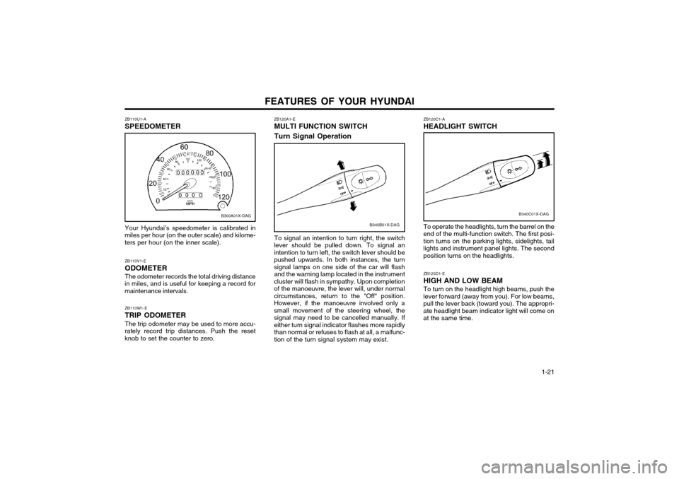
ZB120A1-E MULTI FUNCTION SWITCH Turn Signal Operation
To signal an intention to turn right, the switch
lever should be pulled down. To signal an intention to turn left, the switch lever should bepushed upwards. In both instances, the turnsignal lamps on one side of the car will flashand the warning lamp located in the instrumentcluster will flash in sympathy. Upon completionof the manoeuvre, the lever will, under normalcircumstances, return to the "Off" position.However, if the manoeuvre involved only asmall movement of the steering wheel, thesignal may need to be cancelled manually. Ifeither turn signal indicator flashes more rapidlythan normal or refuses to flash at all, a malfunc-tion of the turn signal system may exist.
ZB110U1-A SPEEDOMETER Your Hyundai’s speedometer is calibrated in
miles per hour (on the outer scale) and kilome- ters per hour (on the inner scale).
B300A01X-DAG
ZB110W1-E TRIP ODOMETER The trip odometer may be used to more accu-
rately record trip distances. Push the reset knob to set the counter to zero. ZB110V1-E ODOMETERThe odometer records the total driving distance
in miles, and is useful for keeping a record for maintenance intervals.
ZB120C1-A HEADLIGHT SWITCH
B340C01X-DAG
ZB120D1-E HIGH AND LOW BEAMTo turn on the headlight high beams, push the
lever forward (away from you). For low beams, pull the lever back (toward you). The appropri-ate headlight beam indicator light will come onat the same time.
To operate the headlights, turn the barrel on the
end of the multi-function switch. The first posi- tion turns on the parking lights, sidelights, taillights and instrument panel lights. The secondposition turns on the headlights.
Page 185 of 249
FEATURES OF YOUR HYUNDAI
1-48 B922F01X-GAT 1. STOP
o Insert the CD to start CD playback, during the radio operation.
o Press the button to stop CD playback and to change the source to Radio.
2. FF/REWWhile the disc is playing, press and hold FF
button to quickly move forward until you reach the desired section of the track and vice versa.
3. TRACK UP/DOWN
o The desired track on the disc currently being played can be selected using the track num-ber.
o Pressing the button once increases the track number by one and pressing the button decreases it.
4. REPEAT
o To repeat the music you are listening to, press the RPT button and to cancel musicrepeat, press again.
FM/AM
5. EJECT Button When the EJECT button is pressed with the CD loaded, the CD is ejected. NOTE:
o To assure proper operation of the unit, keep the vehicle interior temperature with- in a normal range by using the vehicle’sair conditioning or heating system.
o When replacing the fuse, replace it with a fuse having the correct capacity.
o The preset station frequencies are all erased when the car battery is discon-nected. Therefore, all data will have to beset again if this should occur.
o Do not add any oil to the rotating parts.
o This equipment is designed to be used only in a 12 volt DC battery system with negative ground.
o This unit is made of precision parts. Do not attempt to disassemble or adjust anyparts.
o When driving your vehicle, be sure to keep the volume of the unit set lowenough to allow you to hear sounds com-ing from the outside.
o Do not expose this equipment (including the speakers and tape) to water or exces-sive moisture.