check oil Hyundai Atos 2002 Owner's Guide
[x] Cancel search | Manufacturer: HYUNDAI, Model Year: 2002, Model line: Atos, Model: Hyundai Atos 2002Pages: 249, PDF Size: 3.11 MB
Page 227 of 249
DO-IT-YOURSELF MAINTENANCE 6-9
AS60160A
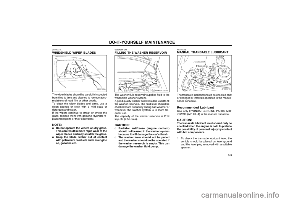
ZG080A1-A
WINDSHIELD WIPER BLADES
The wiper blades should be carefully inspected from time to time and cleaned to remove accu-mulations of road film or other debris. To clean the wiper blades and arms, use a clean sponge or cloth with a mild soap ordetergent and water. If the wipers continue to streak or smear the glass, replace them with genuine Hyundai re-placement parts or their equivalent. NOTE:
o Do not operate the wipers on dry glass. This can result in more rapid wear of the wiper blades and may scratch the glass.
o Keep the blade rubber out of contact with petroleum products such as engineoil, gasoline etc.G090A01X-EAT
FILLING THE WASHER RESERVOIR
The washer fluid reservoir supplies fluid to the
windshield washer system.
A good quality washer fluid should be used to fill
the washer reservoir. The fluid level should be checked more frequently during bad weather orwhenever the washer system is in more fre-quent use.
The capacity of the washer reservoir is 2.19
lmp.qts (2.5 Litres).
CAUTION:
o Radiator antifreeze (engine coolant) should not be used in the washer systembecause it will damage the car’s finish.
o The washer lever should not be pulled and the washer should not be operated ifthe washer reservoir is empty. This can
damage the washer fluid pump. XG100A2-E
MANUAL TRANSAXLE LUBRICANT
G100A01X
Filler plug
Drain plug
The transaxle lubricant should be checked and/
or changed at intervals specified in the mainte- nance schedule. Recommended Lubricant
Use only HYUNDAI GENUINE PARTS MTF
75W/90 (API GL-4) in the manual transaxle.
CAUTION: The transaxle lubricant level should only be
checked when the engine is cold to preludethe possibility of personal injury by contactwith hot components.
1. To check the transaxle lubricant level, the vehicle should be placed on level ground and the level plug removed with a suitablespanner.
G090A01X-DAG
Page 228 of 249
DO-IT-YOURSELF MAINTENANCE
6-10
C090B01X-DAG
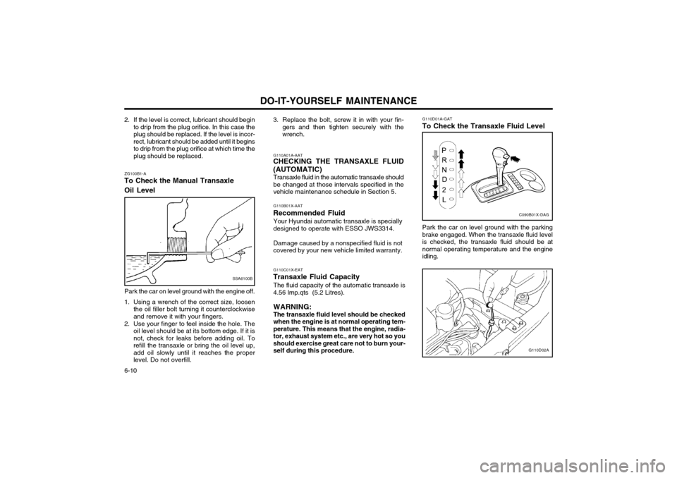
G110D01A-GAT To Check the Transaxle Fluid Level
G110D02A
Park the car on level ground with the parking brake engaged. When the transaxle fluid levelis checked, the transaxle fluid should be atnormal operating temperature and the engineidling.
G110A01A-AAT
CHECKING THE TRANSAXLE FLUID (AUTOMATIC)
Transaxle fluid in the automatic transaxle should be changed at those intervals specified in thevehicle maintenance schedule in Section 5.
3. Replace the bolt, screw it in with your fin-
gers and then tighten securely with thewrench.
G110C01X-EAT
Transaxle Fluid Capacity
The fluid capacity of the automatic transaxle is4.56 lmp.qts (5.2 Litres). WARNING: The transaxle fluid level should be checked when the engine is at normal operating tem-perature. This means that the engine, radia-tor, exhaust system etc., are very hot so youshould exercise great care not to burn your-self during this procedure.
G110B01X-AAT
Recommended Fluid Your Hyundai automatic transaxle is speciallydesigned to operate with ESSO JWS3314. Damage caused by a nonspecified fluid is not covered by your new vehicle limited warranty.
ZG100B1-A
To Check the Manual Transaxle Oil Level
SSA6100B
Park the car on level ground with the engine off.
1. Using a wrench of the correct size, loosen the oil filler bolt turning it counterclockwise and remove it with your fingers.
2. Use your finger to feel inside the hole. The oil level should be at its bottom edge. If it isnot, check for leaks before adding oil. Torefill the transaxle or bring the oil level up,add oil slowly until it reaches the properlevel. Do not overfill.
2. If the level is correct, lubricant should begin
to drip from the plug orifice. In this case theplug should be replaced. If the level is incor-rect, lubricant should be added until it beginsto drip from the plug orifice at which time theplug should be replaced.
Page 234 of 249
DO-IT-YOURSELF MAINTENANCE
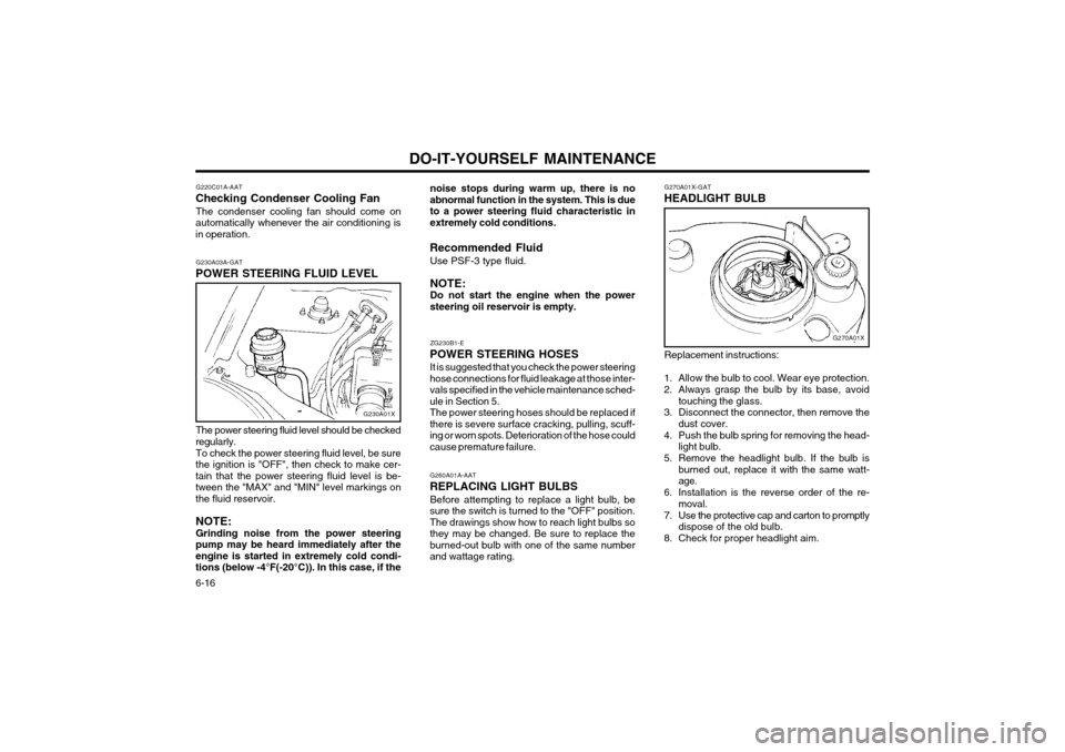
6-16 G270A01X-GAT
HEADLIGHT BULB
G270A01X
Replacement instructions:
1. Allow the bulb to cool. Wear eye protection.
2. Always grasp the bulb by its base, avoid touching the glass.
3. Disconnect the connector, then remove the dust cover.
4. Push the bulb spring for removing the head- light bulb.
5. Remove the headlight bulb. If the bulb is burned out, replace it with the same watt- age.
6. Installation is the reverse order of the re- moval.
7. Use the protective cap and carton to promptly dispose of the old bulb.
8. Check for proper headlight aim.
noise stops during warm up, there is no
abnormal function in the system. This is dueto a power steering fluid characteristic inextremely cold conditions.
Recommended Fluid Use PSF-3 type fluid. NOTE: Do not start the engine when the power
steering oil reservoir is empty. ZG230B1-E
POWER STEERING HOSES It is suggested that you check the power steering hose connections for fluid leakage at those inter-vals specified in the vehicle maintenance sched-ule in Section 5.The power steering hoses should be replaced ifthere is severe surface cracking, pulling, scuff-ing or worn spots. Deterioration of the hose couldcause premature failure.
G260A01A-AAT
REPLACING LIGHT BULBS Before attempting to replace a light bulb, be
sure the switch is turned to the "OFF" position.
The drawings show how to reach light bulbs sothey may be changed. Be sure to replace the
burned-out bulb with one of the same numberand wattage rating.
G220C01A-AAT
Checking Condenser Cooling Fan
The condenser cooling fan should come on
automatically whenever the air conditioning is in operation.
G230A03A-GAT
POWER STEERING FLUID LEVEL
G230A01X
The power steering fluid level should be checked
regularly.
To check the power steering fluid level, be sure
the ignition is "OFF", then check to make cer- tain that the power steering fluid level is be-
tween the "MAX" and "MIN" level markings onthe fluid reservoir.
NOTE: Grinding noise from the power steering
pump may be heard immediately after the engine is started in extremely cold condi-tions (below -4°F(-20°C)). In this case, if the
Page 235 of 249
DO-IT-YOURSELF MAINTENANCE 6-17
WARNING: The halogen bulb contains gas under pres-
sure and if impacted could shatter, and re- sulting in flying fragments. Always wear eye
protection when servicing the bulb. Protectthe bulb against abrasions or scratches andagainst liquids when lighted. Turn on thebulb only when installing in a headlight.Replace the headlight if damaged or cracked.Keep the bulb out of the reach of childrenand dispose of the used bulb with care.
G290A01X-EAT
HEADLIGHT AIMING ADJUSTMENT
G290A01V
Before performing aiming adjustment, make sure
of the following.
Vertical aiming
1. Keep all tires inflated to the correct pres- sure.
2. Place the vehicle on level ground and press the front bumper & rear bumper down sev- eral times.
3. See that the vehicle is unloaded (except for full levels of coolant, engine oil and fuel, andspare tire, jack, and tools). Have the driveror equivalent weight placed in driver's seat.
4. Clean the head lights lens and turn on the headlight (Low beam).
5. Open the bonnet.
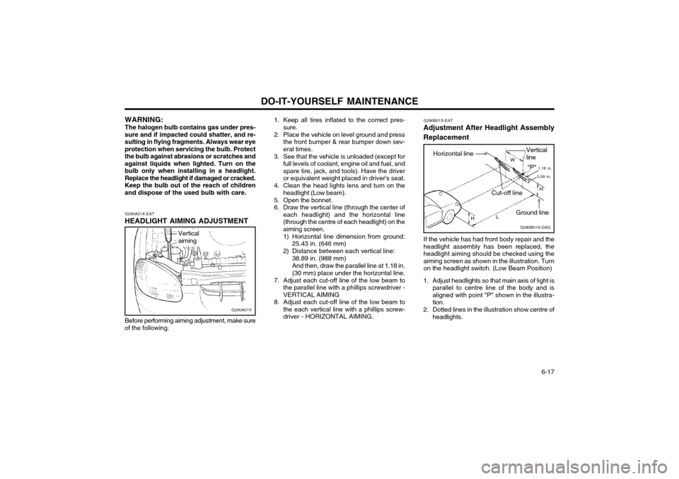
6. Draw the vertical line (through the center of each headlight) and the horizontal line(through the centre of each headlight) on theaiming screen.
1) Horizontal line dimension from ground:25.43 in. (646 mm)
2) Distance between each vertical line: 38.89 in. (988 mm)And then, draw the parallel line at 1.18 in. (30 mm) place under the horizontal line.
7. Adjust each cut-off line of the low beam to the parallel line with a phillips screwdriver -VERTICAL AIMING
8. Adjust each cut-off line of the low beam to the each vertical line with a phillips screw-driver - HORIZONTAL AIMING. G290B01X-EAT
Adjustment After Headlight Assembly Replacement
If the vehicle has had front body repair and the headlight assembly has been replaced, theheadlight aiming should be checked using theaiming screen as shown in the illustration. Turnon the headlight switch. (Low Beam Position)
1. Adjust headlights so that main axis of light is parallel to centre line of the body and isaligned with point "P" shown in the illustra-tion.
2. Dotted lines in the illustration show centre of headlights. G290B01S-DAG
Horizontal lineVertical line
W
0.59 in.
"P" 1.18 in.
Cut-off line
Ground line H
H L
Page 248 of 249
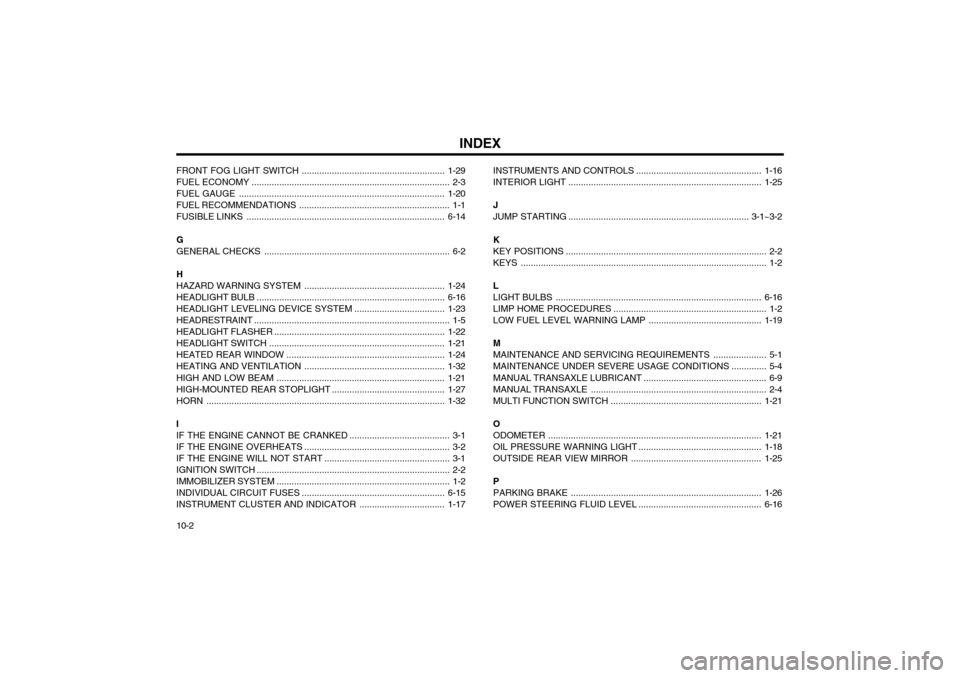
INDEX
10-2
FRONT FOG LIGHT
SWITCH ......................................................... 1-29
FUEL ECONOMY ............................................................................... 2-3
FUEL GAUGE .................................................................................. 1-20
FUEL RECOMMENDATIONS ........... ................................................. 1-1
FUSIBLE LINKS ............................................................................... 6-14
G GENERAL CHECKS .......................................................................... 6-2
H
HAZARD WARNING SYSTEM ........................................................ 1-24
HEADLIGHT BULB ........................................................................... 6-16
HEADLIGHT LEVELING DEVICE SYSTEM ....................................1-23
HEADRESTRAINT .............................................................................. 1-5
HEADLIGHT FLASH ER .................................................................... 1-22
HEADLIGHT SWITCH ...................................................................... 1-21
HEATED REAR WINDOW ................... ............................................1-24
HEATING AND VENTILATION ........................................................ 1-32
HIGH AND LOW BEAM ................................................................... 1-21
HIGH-MOUNTED REAR STOPLIGHT .............................................1-27
HORN ............................................................................................... 1-32
IIF THE ENGINE CANNOT BE CRANKED ........................................ 3-1
IF THE ENGINE OVERHEATS .......................................................... 3-2
IF THE ENGINE WILL NOT START .................................................. 3-1
IGNITION SWITCH ............................................................................. 2-2
IMMOBILIZER SYSTEM ..................................................................... 1-2INDIVIDUAL CIRCUIT FUSES ......................................................... 6-15
INSTRUMENT CLUSTER AND INDICATOR ..................................1-17INSTRUMENTS AND CONTROLS
..................................................1-16
INTERIOR LIGHT ............................................................................. 1-25
JJUMP STARTI NG ........................................................................ 3-1~3-2
KKEY POSITIONS ................................................................................ 2-2
KEYS .................................................................................................. 1-2 L LIGHT BULBS .................................................................................. 6-16
LIMP HOME PROCEDURES ............................................................. 1-2
LOW FUEL LEVEL WARNING LAMP .............................................1-19
M
MAINTENANCE AND SERVICING REQUIREMENTS ..................... 5-1
MAINTENANCE UNDER SEVERE USAGE CONDITIONS .............. 5-4
MANUAL TRANSAXLE LUBRICANT ................................................. 6-9
MANUAL TRANSAXLE ...................................................................... 2-4
MULTI FUNCTION SWITCH ................................. ...........................1-21
OODOMETER ..................................................................................... 1-21
OIL PRESSURE WARNING LIGHT ................................................. 1-18
OUTSIDE REAR VIEW MIRROR ....................................................1-25
PPARKING BRAKE ............................................................................ 1-26
POWER STEERING FLUID LEVEL ................................................. 6-16