stop start Hyundai Atos 2002 Owner's Guide
[x] Cancel search | Manufacturer: HYUNDAI, Model Year: 2002, Model line: Atos, Model: Hyundai Atos 2002Pages: 249, PDF Size: 3.11 MB
Page 225 of 249

DO-IT-YOURSELF MAINTENANCE 6-7
G050D02XG050B01A
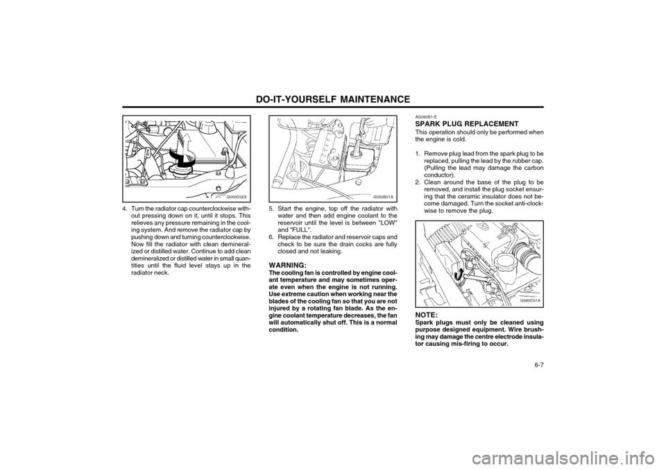
4. Turn the radiator cap counterclockwise with- out pressing down on it, until it stops. This relieves any pressure remaining in the cool-ing system. And remove the radiator cap bypushing down and turning counterclockwise. Now fill the radiator with clean demineral- ized or distilled water. Continue to add cleandemineralized or distilled water in small quan-tities until the fluid level stays up in theradiator neck. 5. Start the engine, top off the radiator with
water and then add engine coolant to thereservoir until the level is between "LOW"and "FULL".
6. Replace the radiator and reservoir caps and check to be sure the drain cocks are fullyclosed and not leaking.
WARNING: The cooling fan is controlled by engine cool-
ant temperature and may sometimes oper- ate even when the engine is not running.Use extreme caution when working near theblades of the cooling fan so that you are notinjured by a rotating fan blade. As the en-gine coolant temperature decreases, the fanwill automatically shut off. This is a normalcondition. AG060B1-E
SPARK PLUG REPLACEMENT
This operation should only be performed when
the engine is cold.
1. Remove plug lead from the spark plug to be replaced, pulling the lead by the rubber cap. (Pulling the lead may damage the carbonconductor).
2. Clean around the base of the plug to be removed, and install the plug socket ensur-ing that the ceramic insulator does not be-come damaged. Turn the socket anti-clock-wise to remove the plug.
G060C01A
NOTE: Spark plugs must only be cleaned using
purpose designed equipment. Wire brush-ing may damage the centre electrode insula-tor causing mis-firing to occur.
Page 234 of 249

DO-IT-YOURSELF MAINTENANCE
6-16 G270A01X-GAT
HEADLIGHT BULB
G270A01X
Replacement instructions:
1. Allow the bulb to cool. Wear eye protection.
2. Always grasp the bulb by its base, avoid touching the glass.
3. Disconnect the connector, then remove the dust cover.
4. Push the bulb spring for removing the head- light bulb.
5. Remove the headlight bulb. If the bulb is burned out, replace it with the same watt- age.
6. Installation is the reverse order of the re- moval.
7. Use the protective cap and carton to promptly dispose of the old bulb.
8. Check for proper headlight aim.
noise stops during warm up, there is no
abnormal function in the system. This is dueto a power steering fluid characteristic inextremely cold conditions.
Recommended Fluid Use PSF-3 type fluid. NOTE: Do not start the engine when the power
steering oil reservoir is empty. ZG230B1-E
POWER STEERING HOSES It is suggested that you check the power steering hose connections for fluid leakage at those inter-vals specified in the vehicle maintenance sched-ule in Section 5.The power steering hoses should be replaced ifthere is severe surface cracking, pulling, scuff-ing or worn spots. Deterioration of the hose couldcause premature failure.
G260A01A-AAT
REPLACING LIGHT BULBS Before attempting to replace a light bulb, be
sure the switch is turned to the "OFF" position.
The drawings show how to reach light bulbs sothey may be changed. Be sure to replace the
burned-out bulb with one of the same numberand wattage rating.
G220C01A-AAT
Checking Condenser Cooling Fan
The condenser cooling fan should come on
automatically whenever the air conditioning is in operation.
G230A03A-GAT
POWER STEERING FLUID LEVEL
G230A01X
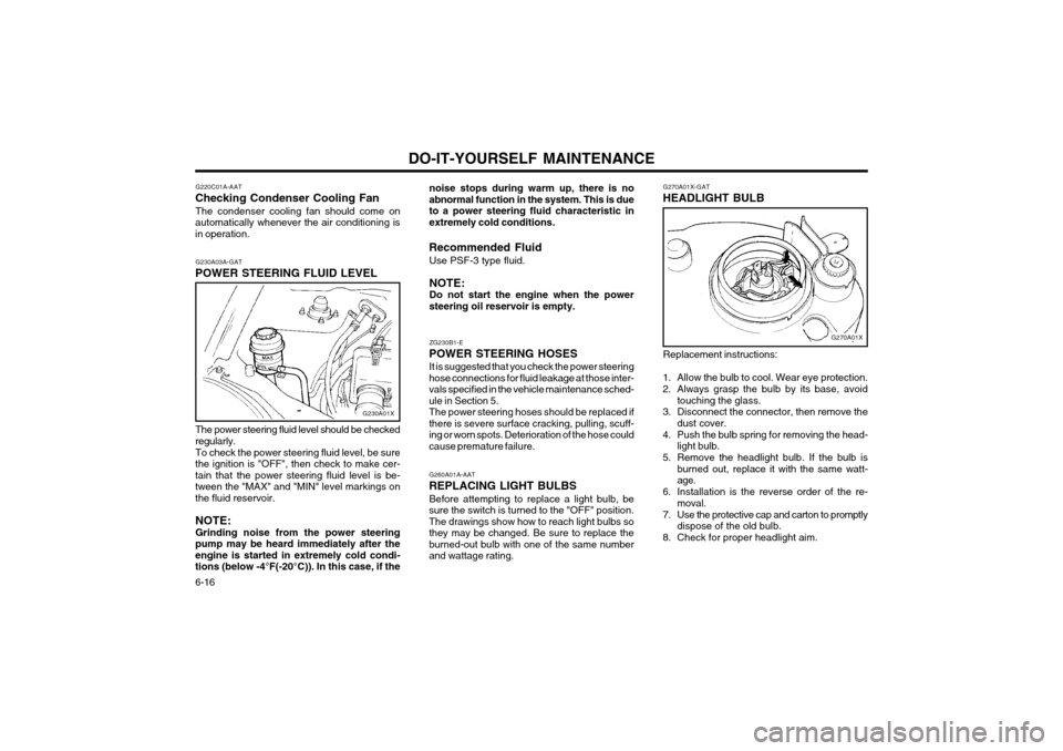
The power steering fluid level should be checked
regularly.
To check the power steering fluid level, be sure
the ignition is "OFF", then check to make cer- tain that the power steering fluid level is be-
tween the "MAX" and "MIN" level markings onthe fluid reservoir.
NOTE: Grinding noise from the power steering
pump may be heard immediately after the engine is started in extremely cold condi-tions (below -4°F(-20°C)). In this case, if the
Page 240 of 249

7-2EMISSION CONTROL SYSTEMS
H020B01A-GAT About the Catalytic ConverterExhaust gases passing through the catalytic
converter cause it to operate at very high tem- peratures. As a result, the introduction of large
amounts of unburned gasoline may cause it to
overheat and create a fire hazard. This can beavoided by observing the following:
o Use unleaded fuel only.
o Maintain your engine in good condition. Ex- tremely high converter temperatures can result from improper operation of the electri-cal, ignition or fuel injection systems.
o If your engine stalls, pings, knocks, or is hard to start, take your car to your Hyundaidealer as soon as possible and have thedifficulty corrected.
o Avoid driving with a very low fuel level. If your run out of gasoline, it could cause theengine to misfire and result in excessive
loading of the catalytic converter.
o Avoid idling the engine for periods longer than 10 minutes.
o Your Hyundai should not be either pushed or pulled to get it started. This can cause thecatalytic converter to overload.
o Take care not to stop your Hyundai over any combustible material such as grass, paper,leaves or rags. As these materials could
come in contact with the catalytic converterand could cause a fire. o Do not touch the catalytic converter or any
other part of the exhaust system while theengine is running as it is very hot and couldresult in burns.
o Remember that your Hyundai dealer is your best source of assistance.
Page 248 of 249

INDEX
10-2
FRONT FOG LIGHT
SWITCH ......................................................... 1-29
FUEL ECONOMY ............................................................................... 2-3
FUEL GAUGE .................................................................................. 1-20
FUEL RECOMMENDATIONS ........... ................................................. 1-1
FUSIBLE LINKS ............................................................................... 6-14
G GENERAL CHECKS .......................................................................... 6-2
H
HAZARD WARNING SYSTEM ........................................................ 1-24
HEADLIGHT BULB ........................................................................... 6-16
HEADLIGHT LEVELING DEVICE SYSTEM ....................................1-23
HEADRESTRAINT .............................................................................. 1-5
HEADLIGHT FLASH ER .................................................................... 1-22
HEADLIGHT SWITCH ...................................................................... 1-21
HEATED REAR WINDOW ................... ............................................1-24
HEATING AND VENTILATION ........................................................ 1-32
HIGH AND LOW BEAM ................................................................... 1-21
HIGH-MOUNTED REAR STOPLIGHT .............................................1-27
HORN ............................................................................................... 1-32
IIF THE ENGINE CANNOT BE CRANKED ........................................ 3-1
IF THE ENGINE OVERHEATS .......................................................... 3-2
IF THE ENGINE WILL NOT START .................................................. 3-1
IGNITION SWITCH ............................................................................. 2-2
IMMOBILIZER SYSTEM ..................................................................... 1-2INDIVIDUAL CIRCUIT FUSES ......................................................... 6-15
INSTRUMENT CLUSTER AND INDICATOR ..................................1-17INSTRUMENTS AND CONTROLS
..................................................1-16
INTERIOR LIGHT ............................................................................. 1-25
JJUMP STARTI NG ........................................................................ 3-1~3-2
KKEY POSITIONS ................................................................................ 2-2
KEYS .................................................................................................. 1-2 L LIGHT BULBS .................................................................................. 6-16
LIMP HOME PROCEDURES ............................................................. 1-2
LOW FUEL LEVEL WARNING LAMP .............................................1-19
M
MAINTENANCE AND SERVICING REQUIREMENTS ..................... 5-1
MAINTENANCE UNDER SEVERE USAGE CONDITIONS .............. 5-4
MANUAL TRANSAXLE LUBRICANT ................................................. 6-9
MANUAL TRANSAXLE ...................................................................... 2-4
MULTI FUNCTION SWITCH ................................. ...........................1-21
OODOMETER ..................................................................................... 1-21
OIL PRESSURE WARNING LIGHT ................................................. 1-18
OUTSIDE REAR VIEW MIRROR ....................................................1-25
PPARKING BRAKE ............................................................................ 1-26
POWER STEERING FLUID LEVEL ................................................. 6-16