Hyundai Coupe 2005 Owner's Manual
Manufacturer: HYUNDAI, Model Year: 2005, Model line: Coupe, Model: Hyundai Coupe 2005Pages: 478, PDF Size: 13.44 MB
Page 391 of 478
3
If the Engine will not Start ........................................... 3-2
Jump Starting .............................................................. 3-3
If the Engine Overheats .............................................. 3-4
Spare Tyre ................................................................... 3-5
In the Event of a Puncture .......................................... 3-6
Changing a Flat Tyre ................................................... 3-6
If Your Vehicle Must be Towed .................................3-11
Emergency Towing .................................................... 3-13
If You Lose Your Keys .............................................. 3-14
IN CASE OF EMERGENCY
3
gkfluk-3.p65
11/21/2005, 3:02 PM
1
Page 392 of 478
3 IN CASE OF EMERGENCY
2IF THE ENGINE WILL NOT START
!
SD020A1-E Seek assistance from the nearest Hyundai authorised repairer with regard to the method of ignition and fuel sys- tem diagnosis.
WARNING:
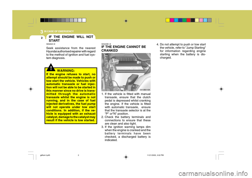
If the engine refuses to start, noattempt should be made to push ortow start the vehicle. Vehicles with automatic transaxle or fuel injec- tion will not be able to be started in this manner since no drive is trans- mitted through the automatictransaxle whilst the engine is not running, and in the case of fuel injected derivatives, the fuel pumpwill not operate under tow start conditions. In addition, if the ve- hicle is equipped with an exhaustcatalyst, damage to the catalyst may result if the vehicle is tow started. SD020B1-E IF THE ENGINE CANNOT BE CRANKED
1. If the vehicle is fitted with manual
transaxle, ensure that the clutch pedal is depressed whilst cranking the engine. If the vehicle is fittedwith automatic transaxle, ensure that the transaxle selector is at the "P" or"N" position.
2. Check the battery terminals and connections to ensure that theseare clean and also tight.
3. If the ignition warning lamps dim when the engine is cranked and thebattery terminals have beenchecked, a discharged battery is indicated. D010B01GK
4. Do not attempt to push or tow start
the vehicle, refer to "Jump Starting" for information regarding engine starting when the battery is dis- charged.
gkfluk-3.p65 11/21/2005, 3:02 PM
2
Page 393 of 478
3
IN CASE OF EMERGENCY
3
!
!
D010C01A-EAT If Engine Turns Over Normally but Does Not Start
1. Check fuel level.
2. With the key in the off position,
Check all connectors at ignition coils and spark plugs. Reconnect any that may be disconnected or loose.
3. Check the fuel line in the engine room.
4. If engine still refuses to start, call a Hyundai authorised repairer or seek other qualified assistance.
D010D01A-EAT If Engine Stalls While Driving
1. Reduce your speed gradually, keep- ing a straight line. Move cautiously off the road to a safe place.
2. Turn on your hazard lamp.
3. Try to start the engine again. If your vehicle will not start, contact aHyundai authorised repairer or seekother qualified assistance. SD030A2-E
CAUTION:
Personal injury and damage to thevehicle may occur if jump startingis not performed correctly. If any doubt exists as to how this opera- tion should be performed, seek as-sistance from qualified personnel.
JUMP STARTING
WARNING:
Motor vehicle batteries contain sulphuric acid and emit hydrogen gas. Protective clothing should beworn and care exercised to prevent the acid from coming into contact with skin or clothing and the ve-hicle. Naked lights should not be permitted in the vicinity of the bat- tery. Care should be exercised toprevent sparks occurring during connection. If acid accidentally comes into contact with skin oreyes, the affected area should im- mediately be flushed with copious amounts of water and medical as-sistance sought.
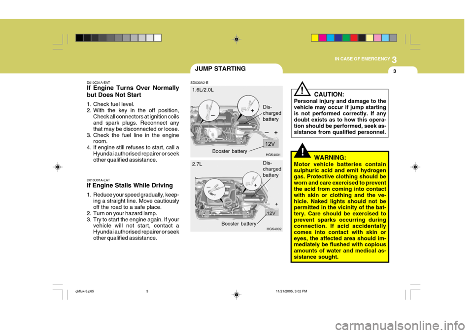
1.6L/2.0L
HGK4001
HGK4002
Dis- chargedbattery
2.7L Booster battery
Dis- chargedbattery
Booster battery
gkfluk-3.p65 11/21/2005, 3:02 PM
3
Page 394 of 478
3 IN CASE OF EMERGENCY
4
7. Swithc "ON" the main beam
headlamps before carefully remov- ing the jumper cables have been removed, switch "OFF" the main beam geadlamps. SD040A2-E If the temperature gauge indicates overheating:
1. Pull off the road and stop as soon as
it is safe to do so.
2. Place the gear selector lever in "P"
(automatic), or neutral (manual transaxle) and set the parking brake. If the air conditioning is on, turn it off.
3. If coolant is running out under the car or steam is coming out fromunder the bonnet stop the engine. Do not open the bonnet until thecoolant has stopped running or the steaming has stopped. If there is no visible loss of coolant and no steam,leave the engine running and check to be sure the engine cooling fan is operating.If the fan is not running, turn the engine off.
4. Check to see if the water pump drive belt is broken. If it is not missing,check to see that it is tight. If the drive belt seems to be satisfac-tory,check for coolant leaking from the radiator, hoses or under the car. (If the air conditioning had been in use,it is normal for cold water to be draining from it).
IF THE ENGINE OVERHEATS
1. Ensure that the booster battery is 12 volt type. If the booster battery is installed in another vehicle, ensure that the two vehicles are not touch- ing.
2. Turn off all unnecessary electrical equipment in both vehicles.
3. Ensure that the engine of the ve- hicle providing the jump start is run- ning prior to connection of the jump cables.
4. Connect the red jump cable to the positive (+) terminal of the boosterbattery and the other end to thepositive (+) terminal of the dis- charged battery.
5. Attach the black jump cable to the negative (-) terminal of thebooster battery, and the other end to a ground point within the enginecompartment of the vehicle with the flat battery. Do not connect to the negative battery terminal of the flatbattery since sparks may be gener- ated with the subsequent risk of explosion.
6. Raise the booster vehicle engine speed to 2,000 r.p.m. and start theengine of the vehicle with the flatbattery. CAUTION:
If the jump cables are incorrectlyinstalled, damage to the vehicle elec-trical system may occur, in particu- lar the electronic components such as the Fuel Injection system com- puter and the Automatic Transaxle computer. The battery must neverbe disconnected whilst the engine is running.
!
gkfluk-3.p65 11/21/2005, 3:02 PM
4
Page 395 of 478
3
IN CASE OF EMERGENCY
5
!
!WARNING:
Whilst the engine is running, keep hands and clothing away from mov- ing parts such as the fan and drive belts to prevent injury.
5. If the water pump drive belt is broken or coolant is leaking out, stop the engine immediately and call the near- est Hyundai authorised repairer forassistance.
WARNING:
Do not remove the radiator cap when the engine is hot since steam and boiling water may be ejected fromthe radiator resulting in burns or scalding.
!
6. If the cause of the overheating can- not be found, wait until the engine temperature has returned to normal. Then, if coolant has been lost, care- fully add coolant to the reservoir(page 6-11) to bring the fluid level in the reservoir up to the base of the radiator fill opening. Fill the coolantexpansion tank to the halfway mark. To ensure the correct water to cool- ant mix is obtained after top up,testing by an authorised repairer is required.
7. Proceed with caution until it is estab- lished that the engine is operatingnormally. If the engine overheats repeatedly, the advice of a Hyundaiauthorised repairer should be sought.
CAUTION:
Serious loss of coolant indicates there is a leak in the cooling system and this should be checked as soonas possible by a Hyundai authorised repairer.D040A01GK-EAT TEMPORARY SPARE TYRE The following instructions for the tem- porary spare tyre should be observed:
1. Check inflation pressure as soon as practical after installing the spare tyre, and adjust to the specified pressure. The tyre pressure should be periodically checked and main-tained at the specified pressure while the tyre is stored.
2. The spare tyre should only be used temporarily and should be returnedto the luggage compartment as soon as the original tyre can be repairedor replaced.
SPARE TYRE
Tyre Size
Inflation Pressure T125/70 R16
420 kPa (60 psi)
Spare Tyre Pressure
3. Continuous use at speeds of over 50 mph (80 km/h) is not recom- mended.
4. As the temporary spare tyre is spe-
cifically designed for your car, itshould not be used on any other vehicle.
gkfluk-3.p65 11/21/2005, 3:02 PM
5
Page 396 of 478
3 IN CASE OF EMERGENCY
6IN THE EVENT OF A PUNC- TURE
SD070A1-ECHANGING A FLAT TYRE
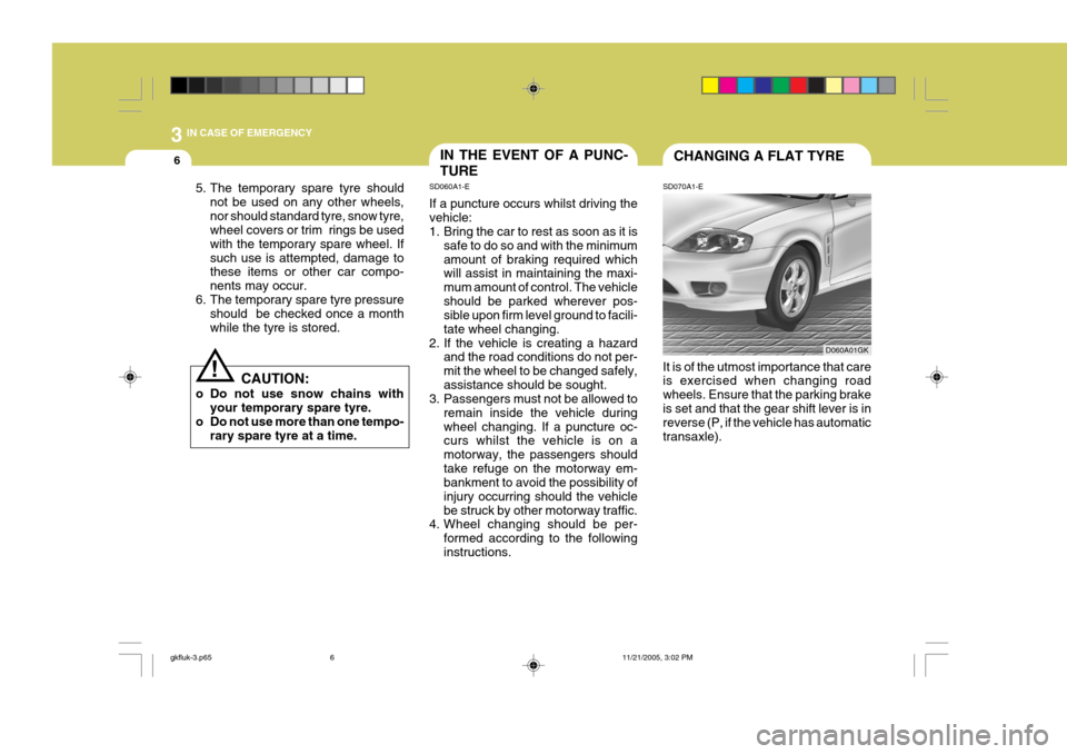
It is of the utmost importance that care is exercised when changing road wheels. Ensure that the parking brakeis set and that the gear shift lever is in reverse (P, if the vehicle has automatic transaxle).
D060A01GK
! CAUTION:
o Do not use snow chains with your temporary spare tyre.
o Do not use more than one tempo-
rary spare tyre at a time.
5. The temporary spare tyre should
not be used on any other wheels, nor should standard tyre, snow tyre, wheel covers or trim rings be used with the temporary spare wheel. Ifsuch use is attempted, damage to these items or other car compo- nents may occur.
6. The temporary spare tyre pressure should be checked once a monthwhile the tyre is stored. SD060A1-E If a puncture occurs whilst driving the vehicle:
1. Bring the car to rest as soon as it is
safe to do so and with the minimum amount of braking required which will assist in maintaining the maxi- mum amount of control. The vehicleshould be parked wherever pos- sible upon firm level ground to facili- tate wheel changing.
2. If the vehicle is creating a hazard and the road conditions do not per-mit the wheel to be changed safely,assistance should be sought.
3. Passengers must not be allowed to
remain inside the vehicle duringwheel changing. If a puncture oc- curs whilst the vehicle is on a motorway, the passengers shouldtake refuge on the motorway em- bankment to avoid the possibility of injury occurring should the vehiclebe struck by other motorway traffic.
4. Wheel changing should be per-
formed according to the followinginstructions.
gkfluk-3.p65 11/21/2005, 3:02 PM
6
Page 397 of 478
3
IN CASE OF EMERGENCY
7
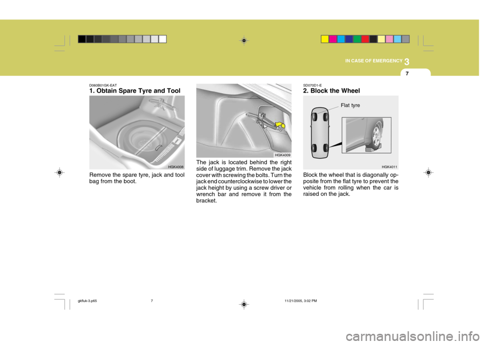
D060B01GK-EAT 1. Obtain Spare Tyre and Tool Remove the spare tyre, jack and tool bag from the boot. HGK4008
HGK4009
The jack is located behind the right side of luggage trim. Remove the jackcover with screwing the bolts. Turn the jack end counterclockwise to lower the jack height by using a screw driver orwrench bar and remove it from the bracket.
Flat tyre
SD070D1-E 2. Block the Wheel Block the wheel that is diagonally op- posite from the flat tyre to prevent thevehicle from rolling when the car is raised on the jack. HGK4011
gkfluk-3.p65
11/21/2005, 3:02 PM
7
Page 398 of 478
3 IN CASE OF EMERGENCY
8
HGK4013 Wrench barHGK4012
HFC4022
Wheel nutwrench
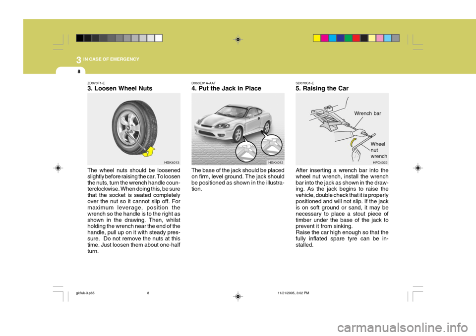
ZD070F1-E 3. Loosen Wheel Nuts The wheel nuts should be loosened slightly before raising the car. To loosenthe nuts, turn the wrench handle coun- terclockwise. When doing this, be sure that the socket is seated completelyover the nut so it cannot slip off. For maximum leverage, position the wrench so the handle is to the right asshown in the drawing. Then, whilst holding the wrench near the end of the handle, pull up on it with steady pres-sure. Do not remove the nuts at this time. Just loosen them about one-half turn. SD070G1-E 5. Raising the Car After inserting a wrench bar into the wheel nut wrench, install the wrenchbar into the jack as shown in the draw- ing. As the jack begins to raise the vehicle, double check that it is properlypositioned and will not slip. If the jack is on soft ground or sand, it may be necessary to place a stout piece oftimber under the base of the jack to prevent it from sinking. Raise the car high enough so that thefully inflated spare tyre can be in- stalled.
D060E01A-AAT 4. Put the Jack in Place
The base of the jack should be placed on firm, level ground. The jack shouldbe positioned as shown in the illustra- tion.
gkfluk-3.p65 11/21/2005, 3:02 PM
8
Page 399 of 478
3
IN CASE OF EMERGENCY
9
!WARNING:
Do not get under the car when it is supported by the jack! The jack is solely designed for wheel chang- ing and is not intended to supportthe vehicle for other purposes. The use of purpose designed supports is necessary whilst the vehicle israised and the operator is required to get underneath.
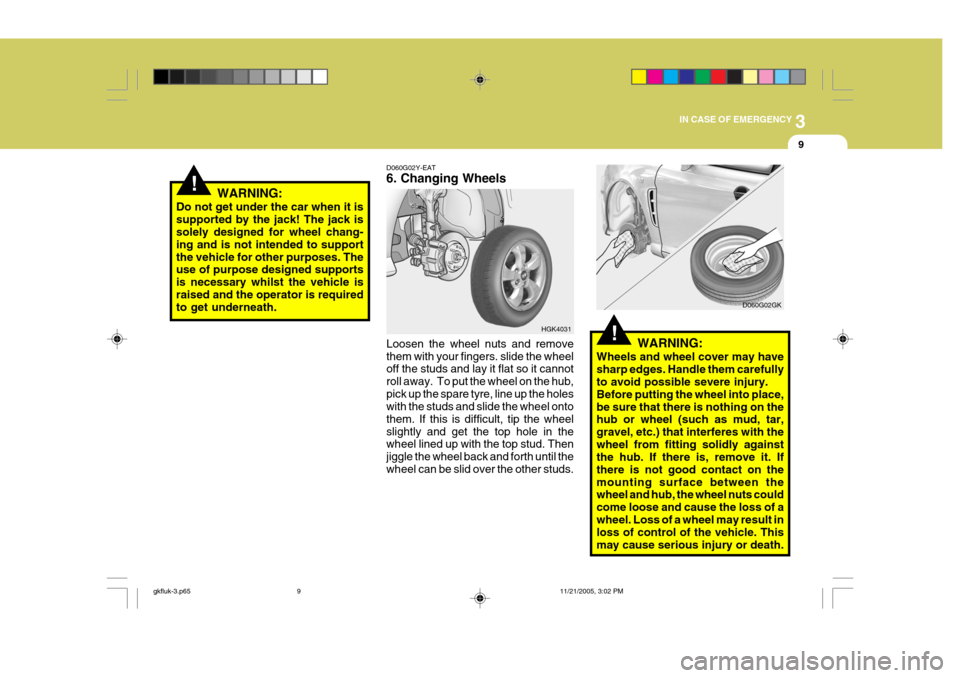
Loosen the wheel nuts and remove them with your fingers. slide the wheel off the studs and lay it flat so it cannot roll away. To put the wheel on the hub,pick up the spare tyre, line up the holes with the studs and slide the wheel onto them. If this is difficult, tip the wheelslightly and get the top hole in the wheel lined up with the top stud. Then jiggle the wheel back and forth until thewheel can be slid over the other studs.
HGK4031
D060G02Y-EAT 6. Changing Wheels!WARNING:
Wheels and wheel cover may have sharp edges. Handle them carefully to avoid possible severe injury. Before putting the wheel into place,be sure that there is nothing on the hub or wheel (such as mud, tar, gravel, etc.) that interferes with thewheel from fitting solidly against the hub. If there is, remove it. If there is not good contact on themounting surface between the wheel and hub, the wheel nuts could come loose and cause the loss of awheel. Loss of a wheel may result in loss of control of the vehicle. This may cause serious injury or death. D060G02GK
gkfluk-3.p65
11/21/2005, 3:02 PM
9
Page 400 of 478
3 IN CASE OF EMERGENCY
10
HGK4014
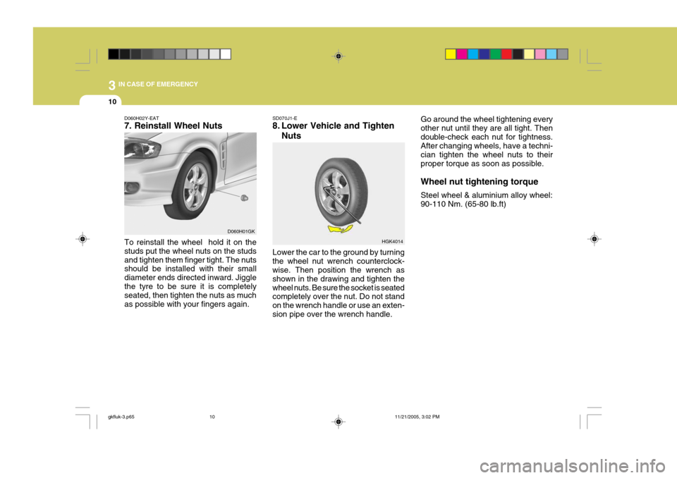
D060H02Y-EAT 7. Reinstall Wheel Nuts To reinstall the wheel hold it on the studs put the wheel nuts on the studsand tighten them finger tight. The nuts should be installed with their small diameter ends directed inward. Jigglethe tyre to be sure it is completely seated, then tighten the nuts as much as possible with your fingers again. SD070J1-E
8. Lower Vehicle and Tighten
Nuts
Lower the car to the ground by turning the wheel nut wrench counterclock- wise. Then position the wrench as shown in the drawing and tighten thewheel nuts. Be sure the socket is seated completely over the nut. Do not stand on the wrench handle or use an exten-sion pipe over the wrench handle.
D060H01GK Go around the wheel tightening everyother nut until they are all tight. Thendouble-check each nut for tightness. After changing wheels, have a techni- cian tighten the wheel nuts to theirproper torque as soon as possible. Wheel nut tightening torque Steel wheel & aluminium alloy wheel: 90-110 Nm. (65-80 lb.ft)
gkfluk-3.p65
11/21/2005, 3:02 PM
10