oil Hyundai Coupe 2006 Service Manual
[x] Cancel search | Manufacturer: HYUNDAI, Model Year: 2006, Model line: Coupe, Model: Hyundai Coupe 2006Pages: 483, PDF Size: 12.73 MB
Page 255 of 483
10
INDEX
3
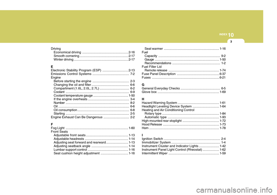
Driving Economical driving .................................................. 2-16
Smooth corneri ng ..................................................... 2-17
Winter driving ........................................................... 2-17
E Electronic Stability Program (ESP) ............................2-13
Emissions Control Systems ........................................ 7-2 Engine Before starting the engine ........................................ 2-3
Changing the oil and filter ......................................... 6-6Compartment (1.6L, 2.0L, 2.7L) ................................ 6-2
Coolant ..................................................................... 6-9
Coolant temperature gauge ......................................1-50
If the engine overheats ............................................. 3-4
Number ..................................................................... 8-2
Oil ............................................................................. 6-6Oil consumption ........................................................ 6-8
Starting ..................................................................... 2-5
Engine Exhaust Can Be Dangerous ............................ 2-2
FFog Light .................................................................... 1-60
Front Seats Adjustable front seats .............................................. 1-13
Adjustable headrests ............................................... 1-14
Adjusting seat forward and rearward ........................ 1-13
Adjusting seatback angle ........................................ 1-14
Lumbar support control ............................................ 1-16
Seat cushion height adjustment .............................. 1-16Seat warmer
............................................................ 1-16
Fuel Capacity ................................................................... 9-2
Gauge ...................................................................... 1-50
Recommendations .................................................... 1-2
Fuel Filler Lid Remote release ....................................................... 1-74
Fuse Panel Description .............................................. 6-37
Fuses ......................................................................... 6-21
G
General Everyday Checks ..... ...................................... 6-5
Glove box ................................................................... 1-69
H Hazard Warning System ............................................. 1-61
Headlight Leveling Device S ystem .............................1-64
Heating and Air Conditioning Control Rotary type .............................................................. 1-84
Automatic type ........................................................ 1-93
High-mounted rear stoplight .. ......................................1-72
Hood Release ............................................................. 1-73
Horn ............................................................................ 1-78
I Ignition Switch ............................................................. 2-4
Immobilizer System ..................................................... 1-4
Instrument Cluster and Indicator Lights ...................... 1-42
Instrument Panel Light Control (Rheostat) .................. 1-62
Intermittent Wiper ....................................................... 1-59
Page 267 of 483
YOUR VEHICLE AT A GLANCE
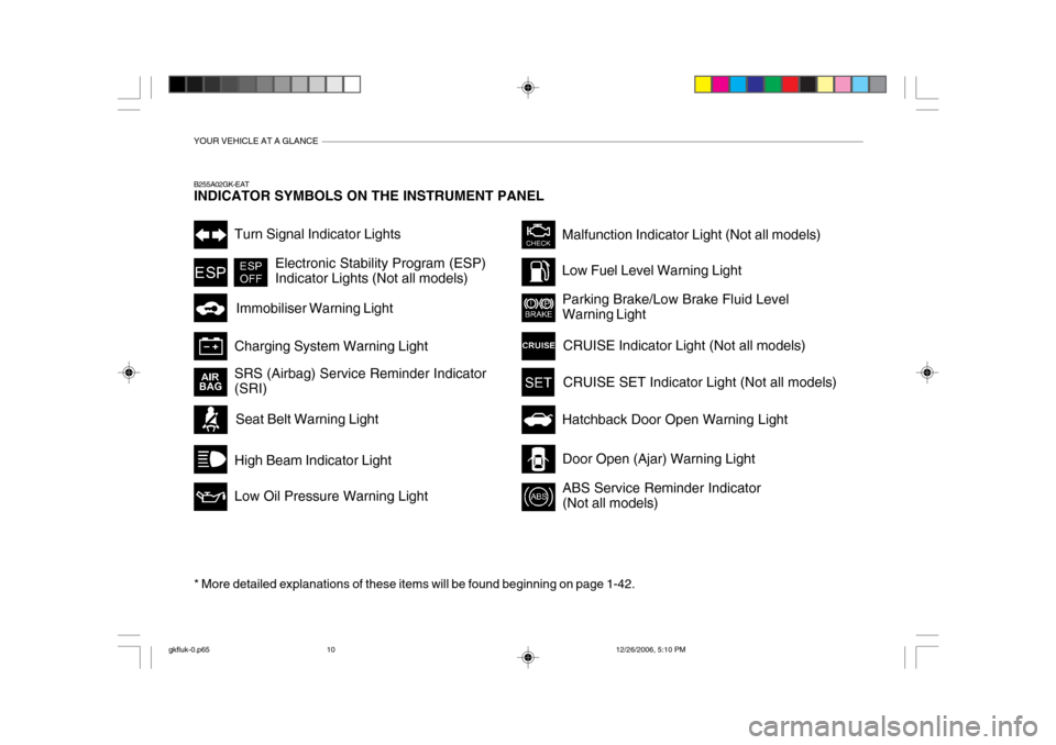
B255A02GK-EAT INDICATOR SYMBOLS ON THE INSTRUMENT PANEL* More detailed explanations of these items will be found beginning on page 1-42.
Turn Signal Indicator Lights Electronic Stability Program (ESP) Indicator Lights (Not all models)Malfunction Indicator Light (Not all models)
SRS (Airbag) Service Reminder Indicator (SRI)
Low Fuel Level Warning Light
High Beam Indicator Light Low Oil Pressure Warning Light
Charging System Warning Light
Seat Belt Warning Light
Immobiliser Warning Light
Hatchback Door Open Warning Light
Door Open (Ajar) Warning Light
ABS Service Reminder Indicator (Not all models)
Parking Brake/Low Brake Fluid Level Warning Light
CRUISE Indicator Light (Not all models)
CRUISE SET Indicator Light (Not all models)
gkfluk-0.p65 12/26/2006, 5:10 PM
10
Page 270 of 483
1
CONTROLS AND EQUIPMENT
3RUNNING IN YOUR NEW HYUNDAI
B020A01S-EAT The longevity and performance of the vehicle are greatly affected by the care exercised during the first 1,000 miles of motoring. Because of modern manu-facturing techniques, rigid guidelines regarding maximum road speeds have become unnecessary. However, cer-tain precautions should be observed in order to obtain the best possible per- formance and useful life from the ve-hicle.
1) Do not race the engine without a
load (i.e revving the engine in neu- tral).
2) During the first 500 miles the maxi- mum engine speed should be re-stricted to 3,000 rpm and gradually increased thereafter.
3) Avoid prolonged constant speed operation. The internal componentsof the engine will become morequickly run in if the operation speed is varied during the running in pe- riod.
4) Never allow the engine to labour. Use the gearbox freely and avoidlarge throttle openings when theengine speed is below 1,500 rpm.BEFORE ENTERING THE VEHICLEAFTER ENTERING THE VEHICLE
YB020A1-E
o Ensure that all windows, mirrors
and lamps are clean.
o Check condition of all tyres.
o Ensure that no fluid leaks are evi-
dent.
o Ensure that the area around the vehicle is clear before driving off. YB020B1-E
o Ensure that all occupants fasten
and correctly adjust seat belts.
o Ensure that seat and head restraint positions are adjusted for optimum safety, control and comfort.
o Adjust interior and exterior rear view mirrors.
o Verify correct operation of lamps, horn and other electrical equipment.
o Ensure that warning lamps illumi-
nate when ignition is turned on.
NOTE: Fluid levels such as engine oil, en- gine coolant, brake and windscreenwasher fluid should be checked daily or at each refuelling, which- ever occurs sooner.
gkfluk-1a.p65 12/26/2006, 5:11 PM
3
Page 308 of 483
1
CONTROLS AND EQUIPMENT
41
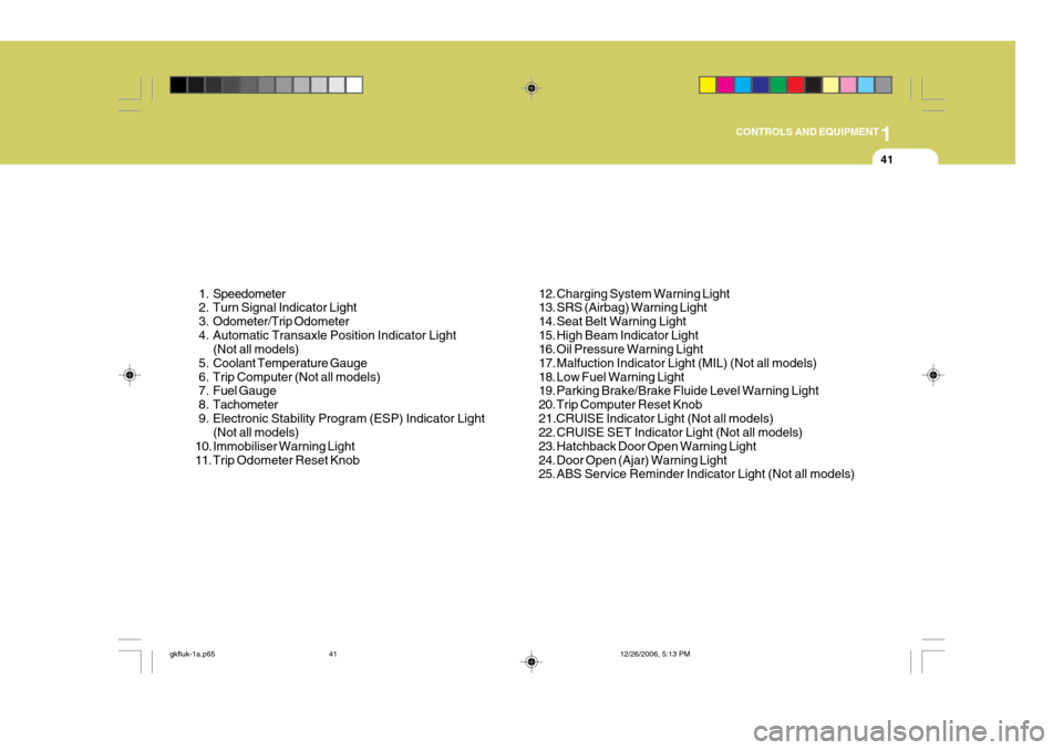
1. Speedometer
2. Turn Signal Indicator Light
3. Odometer/Trip Odometer
4. Automatic Transaxle Position Indicator Light (Not all models)
5. Coolant Temperature Gauge
6. Trip Computer (Not all models)
7. Fuel Gauge
8. Tachometer
9. Electronic Stability Program (ESP) Indicator Light (Not all models)
10. Immobiliser Warning Light
11. Trip Odometer Reset Knob 12. Charging System Warning Light
13. SRS (Airbag) Warning Light
14. Seat Belt Warning Light
15. High Beam Indicator Light
16. Oil Pressure Warning Light
17. Malfuction Indicator Light (MIL) (Not all models)
18. Low Fuel Warning Light
19. Parking Brake/Brake Fluide Level Warning Light
20. Trip Computer Reset Knob21.CRUISE Indicator Light (Not all models)
22. CRUISE SET Indicator Light (Not all models)
23. Hatchback Door Open Warning Light
24. Door Open (Ajar) Warning Light
25. ABS Service Reminder Indicator Light (Not all models)
gkfluk-1a.p65
12/26/2006, 5:13 PM
41
Page 310 of 483
1
CONTROLS AND EQUIPMENT
43
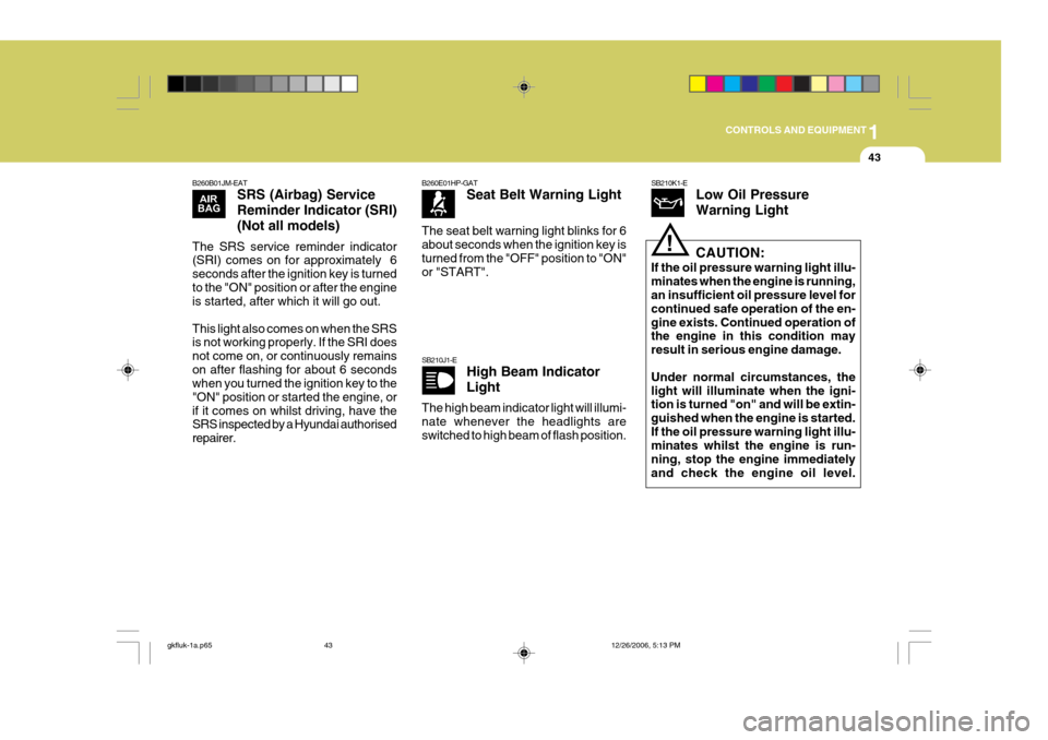
B260B01JM-EAT SRS (Airbag) Service Reminder Indicator (SRI)(Not all models)
The SRS service reminder indicator (SRI) comes on for approximately 6 seconds after the ignition key is turnedto the "ON" position or after the engine is started, after which it will go out. This light also comes on when the SRS is not working properly. If the SRI does not come on, or continuously remainson after flashing for about 6 seconds when you turned the ignition key to the "ON" position or started the engine, orif it comes on whilst driving, have the SRS inspected by a Hyundai authorised repairer.
B260E01HP-GAT Seat Belt Warning Light
The seat belt warning light blinks for 6 about seconds when the ignition key isturned from the "OFF" position to "ON" or "START".
SB210J1-E High Beam Indicator Light
The high beam indicator light will illumi- nate whenever the headlights areswitched to high beam of flash position.
SB210K1-E Low Oil Pressure Warning Light
!CAUTION:
If the oil pressure warning light illu- minates when the engine is running, an insufficient oil pressure level for continued safe operation of the en-gine exists. Continued operation of the engine in this condition may result in serious engine damage. Under normal circumstances, the light will illuminate when the igni- tion is turned "on" and will be extin- guished when the engine is started.If the oil pressure warning light illu- minates whilst the engine is run- ning, stop the engine immediatelyand check the engine oil level.
gkfluk-1a.p65 12/26/2006, 5:13 PM
43
Page 311 of 483
1CONTROLS AND EQUIPMENT
44
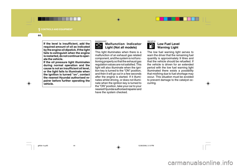
If the level is insufficient, add the required amount of oil as indicated by the engine oil dipstick. If the lightfails to extinguish when the engine is restarted, do not continue to oper- ate the vehicle.If the oil pressure light illuminates during normal operation and the cause is not an insufficient oil level,or the light fails to illuminate when the ignition is turned "on", contact the nearest Hyundai authorised re-pairer before further operating the vehicle.
B260N02A-EAT Malfunction Indicator
Light (Not all models)
This light illuminates when there is a malfunction of an exhaust gas relatedcomponent, and the system is not func- tioning properly so that the exhaust gas regulation values are not satisfied. Thislight will also illuminate when the igni- tion key is turned to the "ON" position, and then it will go out in a few secondsafter the engine is started. If it illumi- nates whilst driving, or does not illumi- nate when the ignition key is turned tothe "ON" position, take your car to your nearest Hyundai authorised repairer and have the system checked.SB210P1-E Low Fuel Level Warning Light
The low fuel warning light serves to warn the driver that the remaining fuelquantity is approximately 9 litres and that the vehicle should be refuelled. If the vehicle is driven for an extendedperiod with the low fuel warning light illuminated there exists a possibility that misfiring due to fuel shortage mayoccur. This situation must be avoided to prevent damage to the catalyst oc- curring.
gkfluk-1a.p65 12/26/2006, 5:13 PM
44
Page 320 of 483
1
CONTROLS AND EQUIPMENT
53MULTI FUNCTION SWITCH
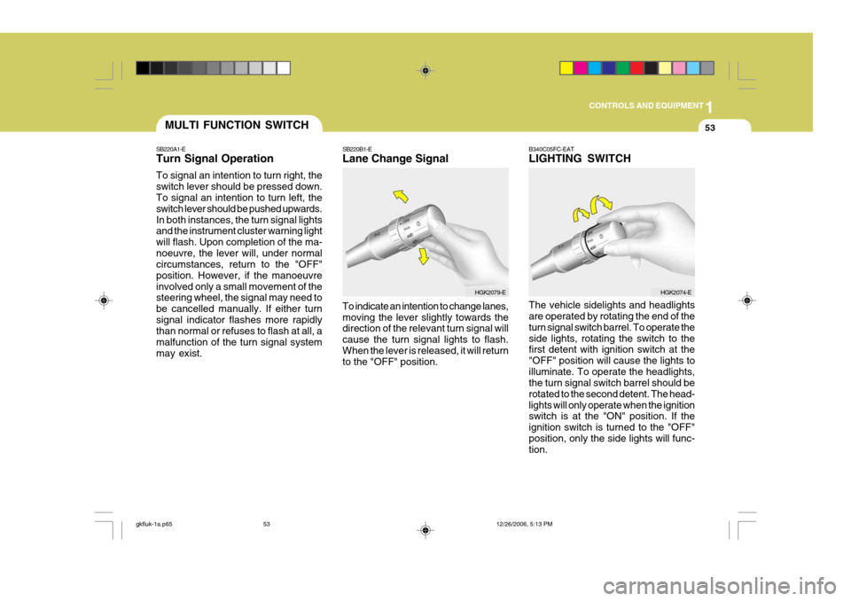
SB220A1-E Turn Signal Operation To signal an intention to turn right, the switch lever should be pressed down. To signal an intention to turn left, the switch lever should be pushed upwards.In both instances, the turn signal lights and the instrument cluster warning light will flash. Upon completion of the ma-noeuvre, the lever will, under normal circumstances, return to the "OFF" position. However, if the manoeuvreinvolved only a small movement of the steering wheel, the signal may need to be cancelled manually. If either turnsignal indicator flashes more rapidly than normal or refuses to flash at all, a malfunction of the turn signal systemmay exist. SB220B1-E Lane Change Signal To indicate an intention to change lanes, moving the lever slightly towards the direction of the relevant turn signal will cause the turn signal lights to flash.When the lever is released, it will return to the "OFF" position.B340C05FC-EAT LIGHTING SWITCH The vehicle sidelights and headlights are operated by rotating the end of the turn signal switch barrel. To operate theside lights, rotating the switch to the first detent with ignition switch at the "OFF" position will cause the lights toilluminate. To operate the headlights, the turn signal switch barrel should be rotated to the second detent. The head-lights will only operate when the ignition switch is at the "ON" position. If the ignition switch is turned to the "OFF"position, only the side lights will func- tion.
HGK2079-EHGK2074-E
gkfluk-1a.p65
12/26/2006, 5:13 PM
53
Page 337 of 483
1CONTROLS AND EQUIPMENT
70HIGH-MOUNTED REAR STOP LIGHTFRONT DOOR EDGE WARN- ING LIGHT
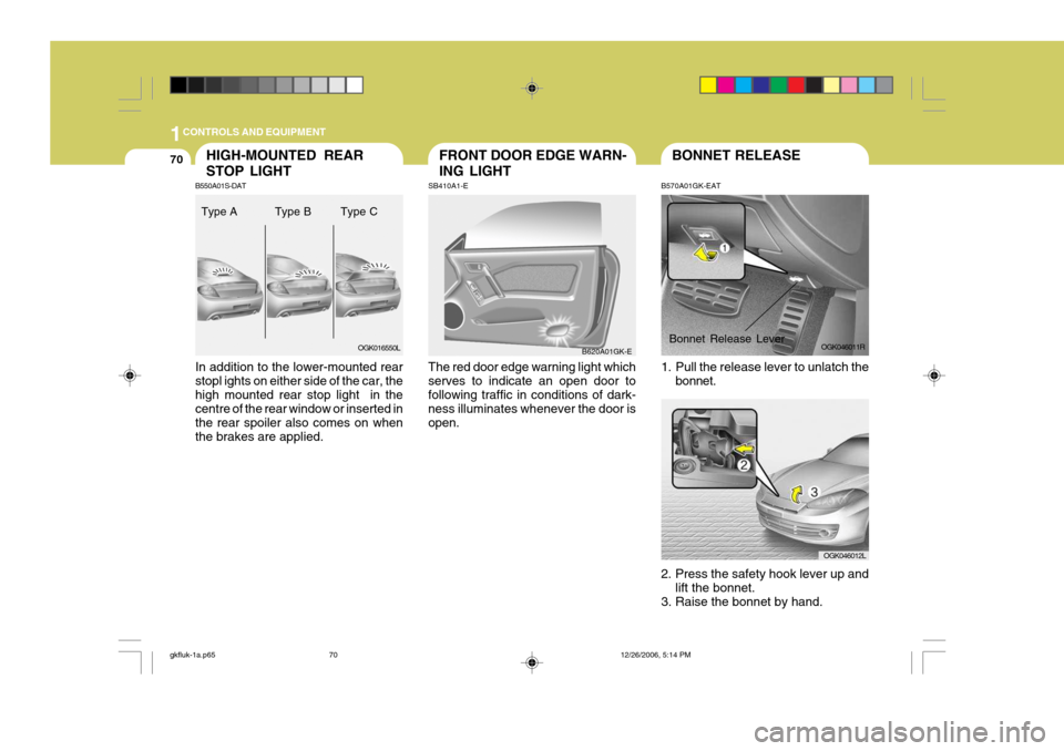
SB410A1-E The red door edge warning light which serves to indicate an open door tofollowing traffic in conditions of dark- ness illuminates whenever the door is open. B620A01GK-EBONNET RELEASE
B570A01GK-EAT
1. Pull the release lever to unlatch the bonnet.
Bonnet Release Lever
OGK046011R
B550A01S-DAT In addition to the lower-mounted rear stopl ights on either side of the car, thehigh mounted rear stop light in the centre of the rear window or inserted in the rear spoiler also comes on whenthe brakes are applied.Type A
OGK016550L
Type B Type C
2. Press the safety hook lever up andlift the bonnet.
3. Raise the bonnet by hand. OGK046012L
gkfluk-1a.p65
12/26/2006, 5:14 PM
70
Page 343 of 483
1CONTROLS AND EQUIPMENT
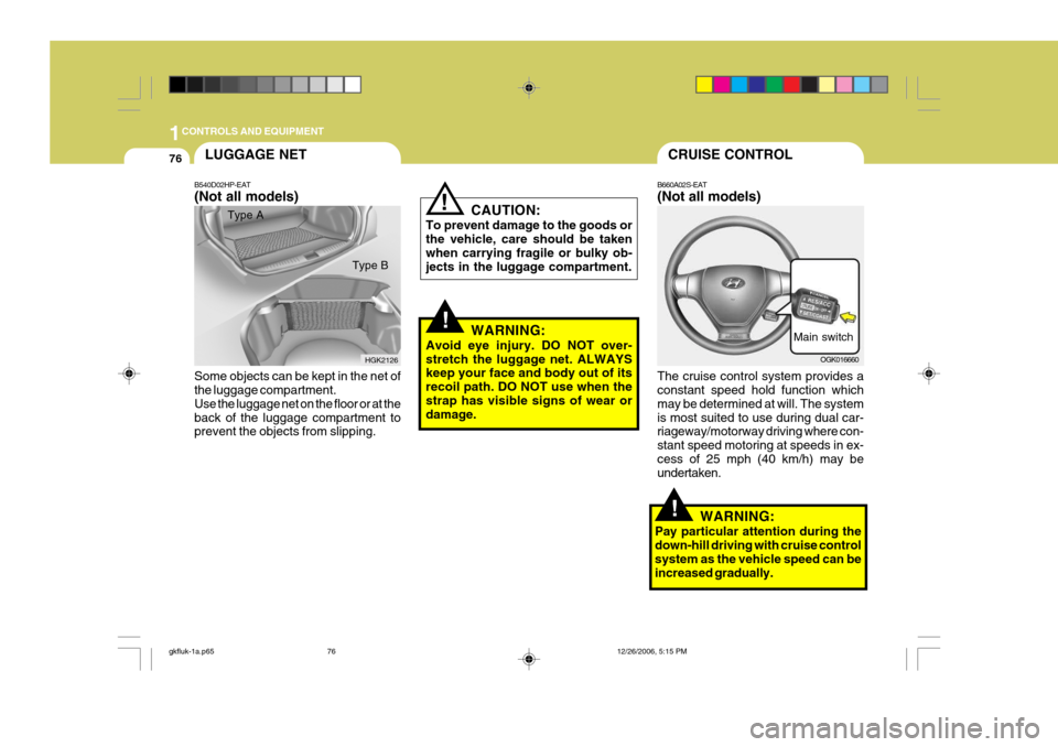
76CRUISE CONTROL
B660A02S-EAT (Not all models) The cruise control system provides a constant speed hold function which may be determined at will. The systemis most suited to use during dual car- riageway/motorway driving where con- stant speed motoring at speeds in ex-cess of 25 mph (40 km/h) may be undertaken. Main switch
OGK016660
!
! CAUTION:
To prevent damage to the goods or the vehicle, care should be taken when carrying fragile or bulky ob- jects in the luggage compartment.
WARNING:
Avoid eye injury. DO NOT over-stretch the luggage net. ALWAYS keep your face and body out of its recoil path. DO NOT use when thestrap has visible signs of wear or damage.
LUGGAGE NET
B540D02HP-EAT (Not all models) Type A
Some objects can be kept in the net of the luggage compartment. Use the luggage net on the floor or at theback of the luggage compartment to prevent the objects from slipping. HGK2126
Type B
!WARNING:
Pay particular attention during the down-hill driving with cruise control system as the vehicle speed can beincreased gradually.
gkfluk-1a.p65 12/26/2006, 5:15 PM
76
Page 370 of 483

1
FEATURES OF YOUR HYUNDAI
103
Damaged Disc Do not attempt to play damaged, warped or cracked discs. It could severelydamage the playback mechanism. Storage When not in use, place your discs in their individual case and store them in a cool place away from the sun, heat,and dust. Do not grip or pull out the disc with your hand while the disc is being pulled intothe unit by the Self Loading mecha- nism. Do not grip or pull out the disc with yourhand while the disc is being pulled into the unit by the self loading mechanism. Do not pull the unit from the dashimmediately after a disc is inserted or the eject switch has been pressed. If the unit is pulled out before an operationis completed, the disc will be unstable in the unit and may be damaged. Do not attempt to insert a disc into theunit when the unit is out of the dash or the power is off.
JB580B1-A Proper Handling
Handle your disc as shown. Do not drop the disc. Hold the disc so you will not leave fingerprints on the surface. If thesurface is scratched, it may cause the pickup to skip signal tracks. Do not affix tape, paper, or gummed labels onthe disc. Do not write on the disc. B850A01L
B850A02L
Keep Your Discs Clean
CARE OF DISCS
Fingerprints, dust, or soil on the surfacecould cause the pickup to skip signaltracks. Wipe the surface clean with a clean soft cloth. If the surface is heavily soiled, dampen a clean soft cloth in asolution of mild neutral detergent to wipe it clean.
gkfluk-1b.p6512/26/2006, 5:18 PM
103