rear Hyundai Coupe 2006 Manual Online
[x] Cancel search | Manufacturer: HYUNDAI, Model Year: 2006, Model line: Coupe, Model: Hyundai Coupe 2006Pages: 483, PDF Size: 12.73 MB
Page 305 of 483
1CONTROLS AND EQUIPMENT
38
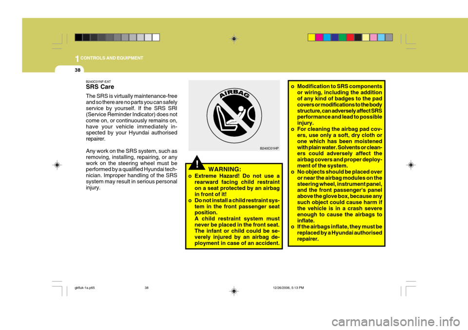
B240C01HP
!WARNING:
o Extreme Hazard! Do not use a rearward facing child restraint on a seat protected by an airbag in front of it!
o Do not install a child restraint sys- tem in the front passenger seatposition. A child restraint system mustnever be placed in the front seat. The infant or child could be se- verely injured by an airbag de-ployment in case of an accident. o Modification to SRS components
or wiring, including the addition of any kind of badges to the pad covers or modifications to the bodystructure, can adversely affect SRS performance and lead to possible injury.
o For cleaning the airbag pad cov- ers, use only a soft, dry cloth orone which has been moistenedwith plain water. Solvents or clean- ers could adversely affect the airbag covers and proper deploy-ment of the system.
o No objects should be placed over
or near the airbag modules on thesteering wheel, instrument panel, and the front passenger's panel above the glove box, because anysuch object could cause harm if the vehicle is in a crash severe enough to cause the airbags toinflate.
o If the airbags inflate, they must be
replaced by a Hyundai authorisedrepairer.
B240C01NF-EAT SRS Care The SRS is virtually maintenance-free and so there are no parts you can safelyservice by yourself. If the SRS SRI (Service Reminder Indicator) does not come on, or continuously remains on,have your vehicle immediately in- spected by your Hyundai authorised repairer. Any work on the SRS system, such as removing, installing, repairing, or anywork on the steering wheel must be performed by a qualified Hyundai tech- nician. Improper handling of the SRSsystem may result in serious personal injury.
gkfluk-1a.p65
12/26/2006, 5:13 PM
38
Page 324 of 483
1
CONTROLS AND EQUIPMENT
57
OGK046051R
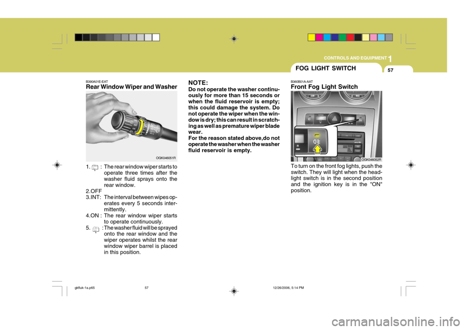
B390A01E-EAT Rear Window Wiper and Washer
1. : The rear window wiper starts to
operate three times after the washer fluid sprays onto the rear window.
2.OFF 3.INT: The interval between wipes op- erates every 5 seconds inter-mittently.
4.ON : The rear window wiper starts
to operate continuously.
5. : The washer fluid will be sprayed onto the rear window and thewiper operates whilst the rearwindow wiper barrel is placed in this position. NOTE: Do not operate the washer continu- ously for more than 15 seconds or when the fluid reservoir is empty;this could damage the system. Do not operate the wiper when the win- dow is dry; this can result in scratch-ing as well as premature wiper blade wear. For the reason stated above,do notoperate the washer when the washer fluid reservoir is empty.
FOG LIGHT SWITCH
OGK046052R
B360B01A-AAT Front Fog Light Switch
To turn on the front fog lights, push the switch. They will light when the head- light switch is in the second position and the ignition key is in the "ON"position.
gkfluk-1a.p65 12/26/2006, 5:14 PM
57
Page 325 of 483
1CONTROLS AND EQUIPMENT
58HAZARD WARNING SYS- TEM
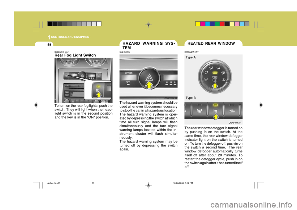
SB240A1-E The hazard warning system should be used whenever it becomes necessaryto stop the car in a hazardous location. The hazard warning system is oper- ated by depressing the switch at whichtime all turn signal lamps will flash simultaneously and the turn signal warning lamps located within the in-strument cluster will flash simulta- neously. The hazard warning system may beturned off by depressing the switch again.
OGK066001R
HEATED REAR WINDOW
B380A02A-EAT The rear window defogger is turned on by pushing in on the switch. At the same time, the rear window defogger indicator light on the switch is turnedon. To turn the defogger off, push in on the switch a second time. The rear window defogger automatically turnsitself off after about 20 minutes. To restart the defogger cycle, push in on the switch again after it has turned itselfoff. OGK046054-1
OGK046053R
B360A01Y-GAT Rear Fog Light Switch To turn on the rear fog lights, push the switch. They will light when the head- light switch is in the second position and the key is in the "ON" position. Type A Type B
gkfluk-1a.p65
12/26/2006, 5:14 PM
58
Page 326 of 483
1
CONTROLS AND EQUIPMENT
59
!
CAUTION:
The inside of the rear windscreen should never be cleaned with a hard or sharp implement since damage to the heating element may occur.The glass should only be cleaned with a soft cloth or chamois leather with the use only of a mild deter-gent or proprietary glass cleaner where necessary. Only horizontal movement of the cloth should bemade when cleaning the glass and care should be exercised to ensure that the heating elements are not damaged by rings or jewellery whilst the glass is being cleaned. NOTE: The engine must be running for the rear window defroster to operate.
INSTRUMENT PANEL ILLUMINATION CONTROL
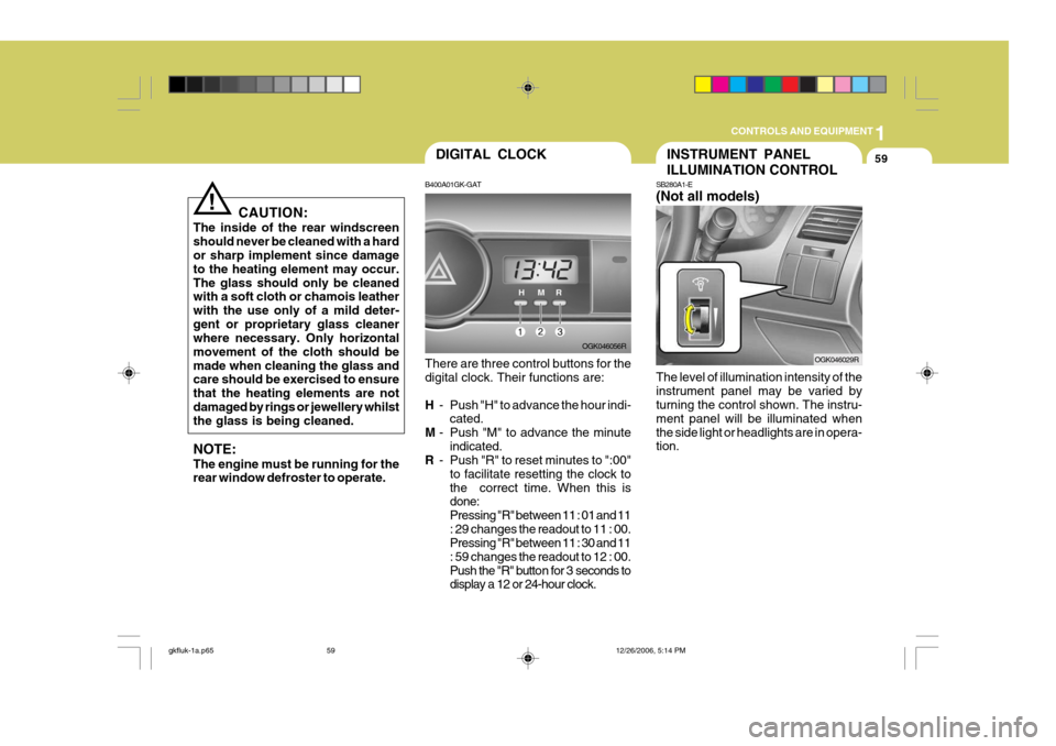
SB280A1-E (Not all models) The level of illumination intensity of the instrument panel may be varied by turning the control shown. The instru- ment panel will be illuminated whenthe side light or headlights are in opera- tion. OGK046029RDIGITAL CLOCK
B400A01GK-GAT There are three control buttons for the digital clock. Their functions are: H - Push "H" to advance the hour indi-
cated.
M - Push "M" to advance the minute
indicated.
R - Push "R" to reset minutes to ":00"
to facilitate resetting the clock to the correct time. When this is done: Pressing "R" between 11 : 01 and 11: 29 changes the readout to 11 : 00. Pressing "R" between 11 : 30 and 11 : 59 changes the readout to 12 : 00.
Push the "R" button for 3 seconds to display a 12 or 24-hour clock. OGK046056R
gkfluk-1a.p65
12/26/2006, 5:14 PM
59
Page 329 of 483
1CONTROLS AND EQUIPMENT
62SUNSHADE
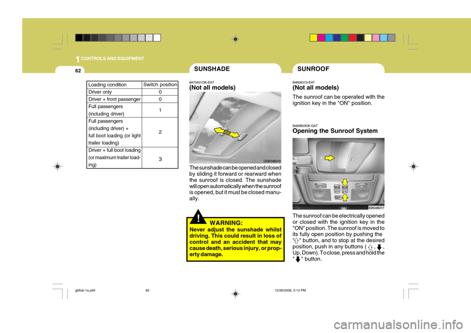
B470A01GK-EAT (Not all models) The sunshade can be opened and closed by sliding it forward or rearward when the sunroof is closed. The sunshadewill open automatically when the sunroof is opened, but it must be closed manu- ally. OGK046019
!WARNING:
Never adjust the sunshade whilst driving. This could result in loss of control and an accident that may cause death, serious injury, or prop-erty damage.
SUNROOF
B460A01S-EAT (Not all models) The sunroof can be operated with the ignition key in the "ON" position.
B460B03GK-GAT Opening the Sunroof System The sunroof can be electrically opened or closed with the ignition key in the"ON" position. The sunroof is moved to its fully open position by pushing the " " button, and to stop at the desiredposition, push in any buttons (
, ,
Up, Down). To close, press and hold the " " button.
OGK046017
Switch position
0 0 1 2
3Loading condition Driver only Driver + front passengerFull passengers (including driver) Full passengers(including driver) + full boot loading (or light trailer loading)Driver + full boot loading (or maximum trailer load- ing)
gkfluk-1a.p65 12/26/2006, 5:14 PM
62
Page 331 of 483
1CONTROLS AND EQUIPMENT
64
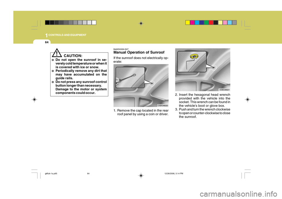
2. Insert the hexagonal head wrenchprovided with the vehicle into the socket. This wrench can be found in the vehicle's boot or glove box.
3. Push and turn the wrench clockwise
to open or counter-clockwise to closethe sunroof.
OGK046021
B460D03GK-EAT Manual Operation of Sunroof If the sunroof does not electrically op- erate:
1. Remove the cap located in the rear
roof panel by using a coin or driver.
OGK046020
! CAUTION:
o Do not open the sunroof in se- verely cold temperature or when it is covered with ice or snow.
o Periodically remove any dirt that
may have accumulated on theguide rails.
o Do not press any sunroof control
button longer than necessary.Damage to the motor or system components could occur.
gkfluk-1a.p65 12/26/2006, 5:14 PM
64
Page 333 of 483
1CONTROLS AND EQUIPMENT
66
!
GLOVE BOX
B500A01A-EAT
WARNING:
To avoid the possibility of injury, the glove box lid must be keptclosed whilst the vehicle is in mo- tion.
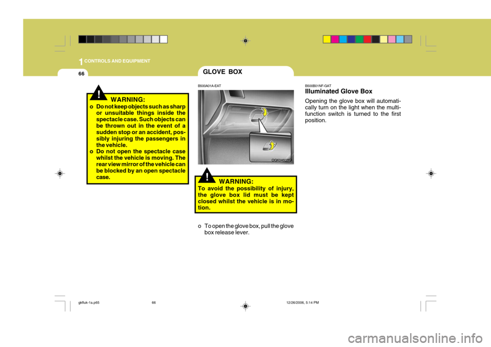
o To open the glove box, pull the glove box release lever. OGK046075R
!WARNING:
o Do not keep objects such as sharp or unsuitable things inside the spectacle case. Such objects canbe thrown out in the event of a sudden stop or an accident, pos- sibly injuring the passengers inthe vehicle.
o Do not open the spectacle case
whilst the vehicle is moving. Therear view mirror of the vehicle can be blocked by an open spectacle case. B500B01NF-GAT Illuminated Glove Box Opening the glove box will automati- cally turn on the light when the multi-function switch is turned to the first position.
gkfluk-1a.p65
12/26/2006, 5:14 PM
66
Page 334 of 483
1
CONTROLS AND EQUIPMENT
67
!
!
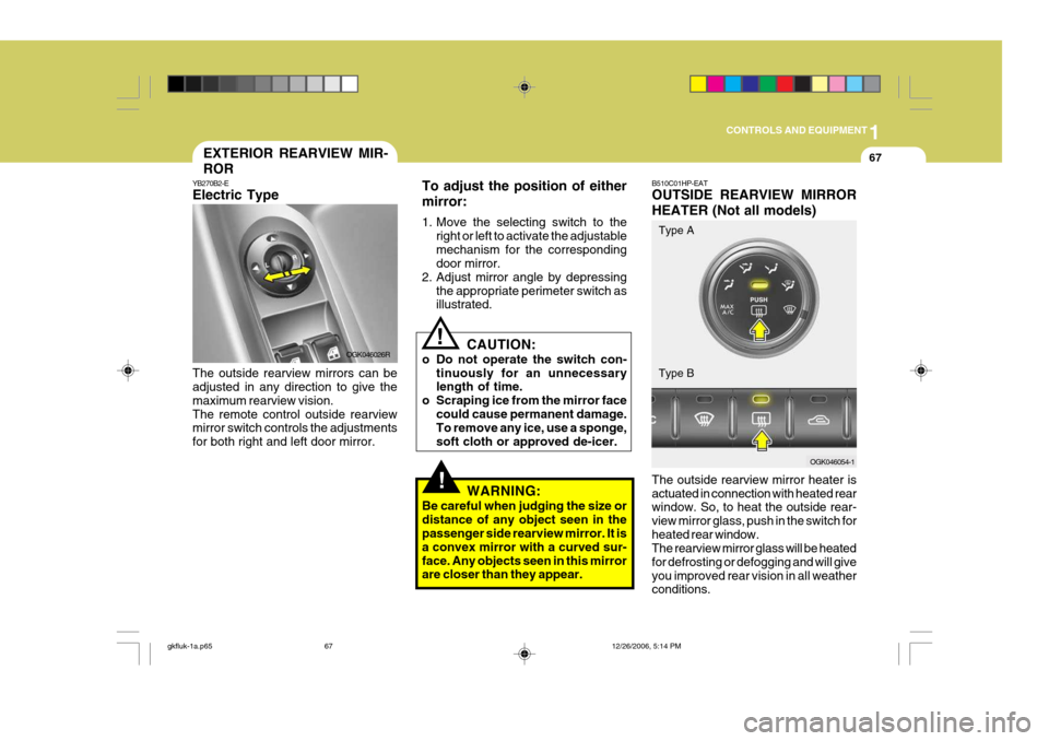
To adjust the position of either mirror:
1. Move the selecting switch to the
right or left to activate the adjustable mechanism for the corresponding door mirror.
2. Adjust mirror angle by depressing
the appropriate perimeter switch asillustrated.
CAUTION:
o Do not operate the switch con- tinuously for an unnecessarylength of time.
o Scraping ice from the mirror face
could cause permanent damage.To remove any ice, use a sponge, soft cloth or approved de-icer.
WARNING:
Be careful when judging the size ordistance of any object seen in the passenger side rearview mirror. It is a convex mirror with a curved sur-face. Any objects seen in this mirror are closer than they appear.
EXTERIOR REARVIEW MIR- ROR
YB270B2-E Electric Type The outside rearview mirrors can be adjusted in any direction to give the maximum rearview vision.The remote control outside rearview mirror switch controls the adjustments for both right and left door mirror. OGK046026R B510C01HP-EAT OUTSIDE REARVIEW MIRROR HEATER (Not all models) The outside rearview mirror heater is actuated in connection with heated rear window. So, to heat the outside rear- view mirror glass, push in the switch forheated rear window. The rearview mirror glass will be heated for defrosting or defogging and will giveyou improved rear vision in all weather conditions.
OGK046054-1
Type A Type B
gkfluk-1a.p65
12/26/2006, 5:14 PM
67
Page 335 of 483
1CONTROLS AND EQUIPMENT
68
!
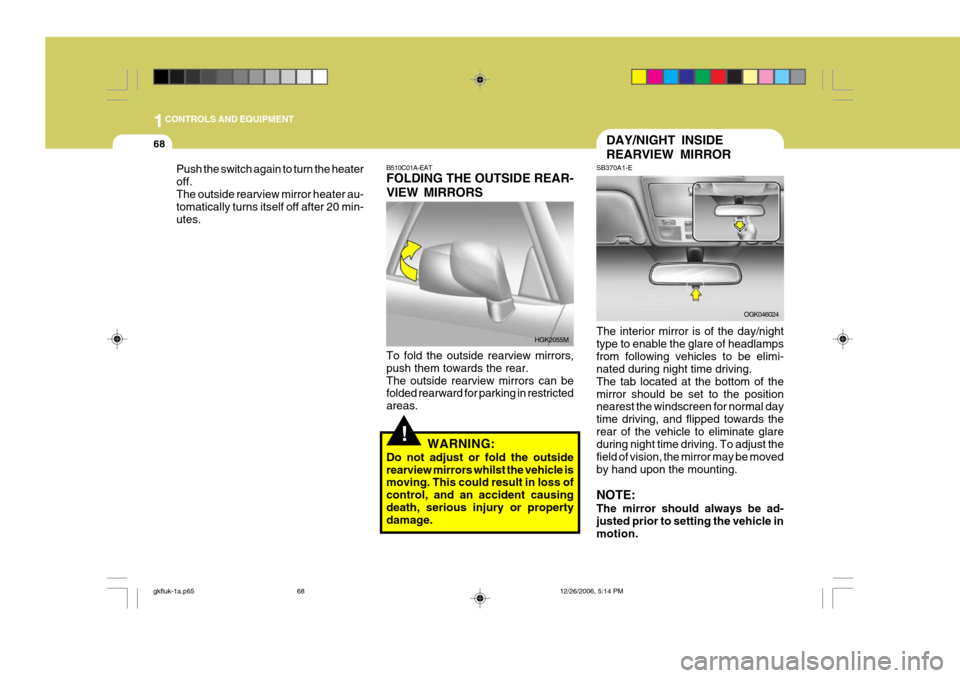
B510C01A-EAT FOLDING THE OUTSIDE REAR- VIEW MIRRORS To fold the outside rearview mirrors, push them towards the rear.The outside rearview mirrors can be folded rearward for parking in restricted areas.
WARNING:
Do not adjust or fold the outsiderearview mirrors whilst the vehicle is moving. This could result in loss of control, and an accident causingdeath, serious injury or property damage. HGK2055M
DAY/NIGHT INSIDE REARVIEW MIRROR
SB370A1-E The interior mirror is of the day/night type to enable the glare of headlampsfrom following vehicles to be elimi- nated during night time driving. The tab located at the bottom of themirror should be set to the position nearest the windscreen for normal day time driving, and flipped towards therear of the vehicle to eliminate glare during night time driving. To adjust the field of vision, the mirror may be movedby hand upon the mounting. NOTE: The mirror should always be ad- justed prior to setting the vehicle in motion.
OGK046024
Push the switch again to turn the heater off.The outside rearview mirror heater au- tomatically turns itself off after 20 min- utes.
gkfluk-1a.p65
12/26/2006, 5:14 PM
68
Page 336 of 483
1
CONTROLS AND EQUIPMENT
69
!
PARKING BRAKE
B530A03A-EAT The parking brake must always be set when the vehicle is to be left unattended.When the parking brake is applied, and the ignition key is at the "ON" position, the parking brake warning light will be
illuminated. Before driving the vehicle, the parking brake must be fully released and the warning light extinguished.
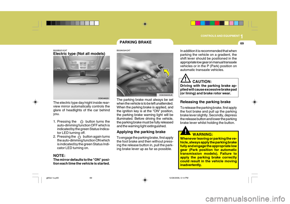
Applying the parking brake To engage the parking brake, first apply the foot brake and then without press- ing the release button in, pull the park- ing brake lever up as far as possible.
B520B02O-EAT Electric type (Not all models) The electric type day/night inside rear- view mirror automatically controls the glare of headlights of the car behindyou.
1. Pressing the button turns the auto-dimming function OFF which is indicated by the green Status Indica- tor LED turning off.
2. Pressing the button again turns the auto-dimming function ON whichis indicated by the green Status Indi-cator LED turning on.
NOTE: The mirror defaults to the "ON" posi- tion each time the vehicle is started. OGK046025In addition it is recommended that when parking the vehicle on a gradient, theshift lever should be positioned in the appropriate low gear on manual transaxle vehicles or in the P (Park) position onautomatic transaxle vehicles.
OGK056005UK
CAUTION:
Driving with the parking brake ap- plied will cause excessive brake pad (or lining) and brake rotor wear. Releasing the parking brake To release the parking brake, first apply the foot brake and pull up the parking brake lever slightly. Secondly, depress the release button and lower the parkingbrake lever whilst holding the button.
WARNING:
Whenever leaving or parking the ve-hicle, always apply the parking brake fully and engage the appropriate low gear (Park position for automatictransmission models). Failure to apply the parking brake correctly could result in the vehicle movinginadvertently.
!
gkfluk-1a.p65 12/26/2006, 5:14 PM
69