boot Hyundai Elantra 2009 Инструкция по эксплуатации (in Russian)
[x] Cancel search | Manufacturer: HYUNDAI, Model Year: 2009, Model line: Elantra, Model: Hyundai Elantra 2009Pages: 308, PDF Size: 15.03 MB
Page 107 of 308
Features of your vehicle
52
4
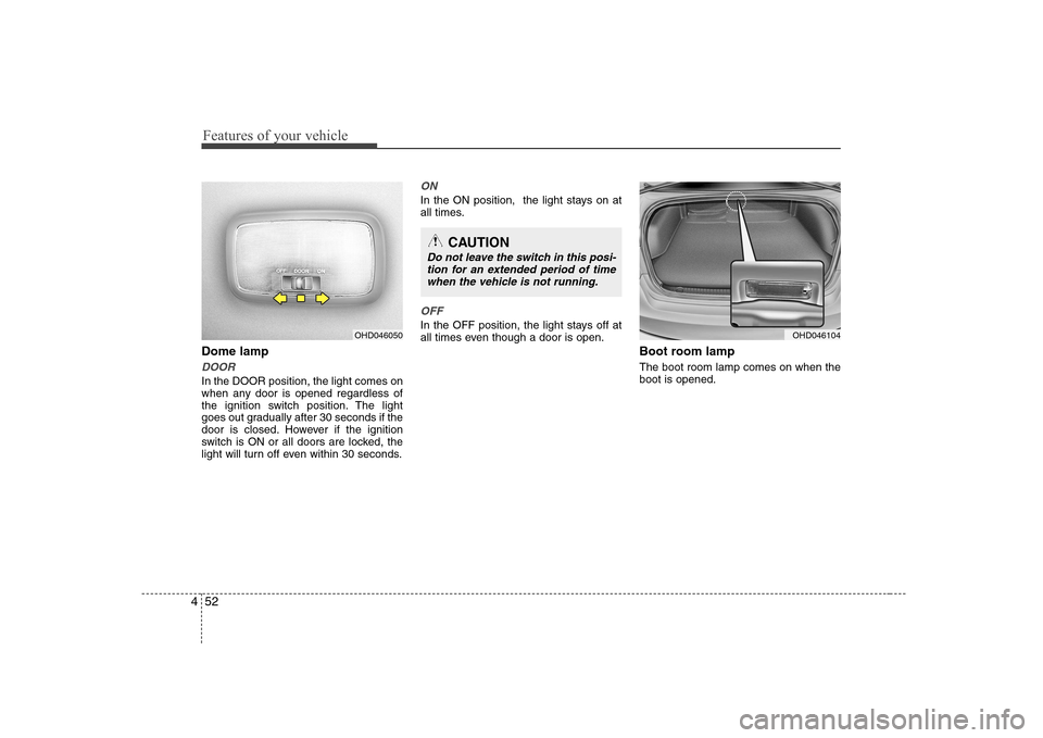
Dome lamp
DOOR
In the DOOR position, the light comes on
when any door is opened regardless of
the ignition switch position. The light
goes out gradually after 30 seconds if the
door is closed. However if the ignition
switch is ON or all doors are locked, the
light will turn off even within 30 seconds.
ON
In the ON position, the light stays on at
all times.
OFF
In the OFF position, the light stays off at
all times even though a door is open.
Boot room lamp The boot room lamp comes on when the boot is opened.OHD046050
CAUTION
Do not leave the switch in this posi-tion for an extended period of timewhen the vehicle is not running.
OHD046104
Page 164 of 308
Driving your vehicle
2
5
WARNING - ENGINE EXHAUST CAN BE DANGEROUS!
Engine exhaust fumes can be extremely dangerous. If, at any time, you smell exhaust fumes inside the vehicle, open the win-
dows immediately.
• Do not inhale exhaust fumes.
Exhaust fumes contain carbon monoxide, a colourless, odourless gas that can cause unconsciousness and death by asphyx- iation.
The exhaust system should be checked whenever the vehicle is raised to change the oil or for any other purpose. If you hear
a change in the sound of the exhaust or if you drive over something that strikes the underneath side of the car, have the
exhaust system checked as soon as possible by an authorised Hyundai dealer.
Letting the engine idle in your garage, even with the garage door open, is a hazardous practice. Never run the engine in your
garage any longer than it takes to start the engine and back the car out.
If it is necessary to idle the engine for a prolonged period with people inside the car, be sure to do so only in an open area
with the air intake set at "Fresh" and fan operating at one of the higher speeds so fresh air is drawn into the interior.
If you must drive with the boot lid open because you are carrying objects that make this necessary:
1. Close all windows.
2. Open side vents.
3. Set the air intake control at "Fresh", the air flow control at "Floor" or "Face" and the fan at one of the higher speeds.
To assure proper operation of the ventilation system, be sure the ventilation air intakes located just in front of the windshie ld are
kept clear of snow, ice, leaves or other obstructions.
Page 167 of 308
55
Driving your vehicle
Starting the petrol engine
1. Make sure the hand brake is applied. 2.Manual Transaxle - Depress the
clutch pedal fully and shift the
transaxle into Neutral. Keep the clutch
pedal and brake pedal depressed
while turning the ignition switch to the
start position.
Automatic Transaxle - Place the
transaxle shift lever in P (Park).
Depress the brake pedal fully.
You can also start the engine when
the shift lever is in the N (Neutral)position.
3. Turn the ignition switch to START and hold it there until the engine starts (a
maximum of 10 seconds), then
release the key. 4. In extremely cold weather (below
-18°C / 0°F) or after the vehicle has
not been operated for several days, let
the engine warm up without depress-
ing the accelerator.
Whether the engine is cold or warm, it
should be started without depressing
the accelerator.
WARNING - Ignition key
Never turn the ignition switch to LOCK or ACC while the vehicle is
moving. This would result in loss
of directional control and braking
function, which could cause anaccident.
The anti-theft steering column lock is not a substitute for the hand
brake. Before leaving the driver’s
seat, always make sure the shift
lever is engaged in P (Park) for theautomatic transaxle and set the
hand brake fully and shut the
engine off. Unexpected and sud-
den vehicle movement may occurif these precautions are not taken.
Never reach for the ignition switch, or any other controls through the
steering wheel while the vehicle is
in motion. The presence of yourhand or arm in this area could
cause a loss of vehicle control, an
accident and serious bodily injuryor death.
Do not place any movable objects around the driver’s seat as they
may move while driving, interferewith the driver and lead to an acci-dent.WARNING
Always wear appropriate shoes
when operating your vehicle.
Unsuitable shoes (high heels, ski
boots,etc.) may interfere with yourability to use the brake and acceler-
ator pedal, and the clutch (ifequipped).
CAUTION
If the engine stalls while you are in motion, do not attempt to move theshift lever to the P (Park) position. Iftraffic and road conditions permit, you may put the shift lever in the N
(Neutral) position while the vehicleis still moving and turn the ignition switch to the START position in an
attempt to restart the engine.
STARTING THE ENGINE
CAUTION
Do not crank the engine for morethan 10 seconds. If the engine stalls or fails to start, wait 5 to 10 secondsbefore cranking the engine again. Improper use of the starter motormay cause damage to it.
Page 208 of 308
Driving your vehicle
46
5
This section will guide you in the proper
loading of your vehicle and/or trailer, to
keep your loaded vehicle weight within its
design rating capability, with or without a
trailer. Properly loading your vehicle will
provide maximum return of the vehicle
design performance. Before loading your
vehicle, familiarise yourself with the fol-
lowing terms for determining your vehi-
cle's weight ratings, with or without a
trailer, from the vehicle's specificationsand the compliance plate: Base curb weight
This is the weight of the vehicle including a full tank of fuel and all standard equip-
ment. It does not include passengers,
cargo, or optional equipment.
Vehicle curb weight
This is the weight of your new vehicle
when you picked it up from your dealer
plus any aftermarket equipment.
Cargo weight
This figure includes all weight added to
the Base Curb Weight, including cargoand optional equipment. GAW (Gross axle weight)
This is the total weight placed on each
axle (front and rear) - including vehicle
curb weight and all payload.
GAWR (Gross axle weight rating)
This is the maximum allowable weight
that can be carried by a single axle (front
or rear). These numbers are shown on
the compliance plate.
The total load on each axle must never
exceed its GAWR.
GVW (Gross vehicle weight)
This is the Base Curb Weight plus actual
Cargo Weight plus passengers.
GVWR (Gross vehicle weight rating)
This is the maximum allowable weight of
the fully loaded vehicle (including all
options, equipment, passengers and
cargo). The GVWR is shown on the com-pliance plate located inside boot.
Overloading
WEIGHT OF THE VEHICLE
WARNING -
Vehicle weight
The gross axle weight rating
(GAWR) and the gross vehicle
weight rating (GVWR) for your vehi-
cle are on the manufacturer's plate
located to the boot. Exceedingthese ratings can cause an acci-
dent or vehicle damage. You can
calculate the weight of your load byweighing the items (and people)
before putting them in the vehicle.
Be careful not to overload your
vehicle.
Page 235 of 308
Maintenance
10
7
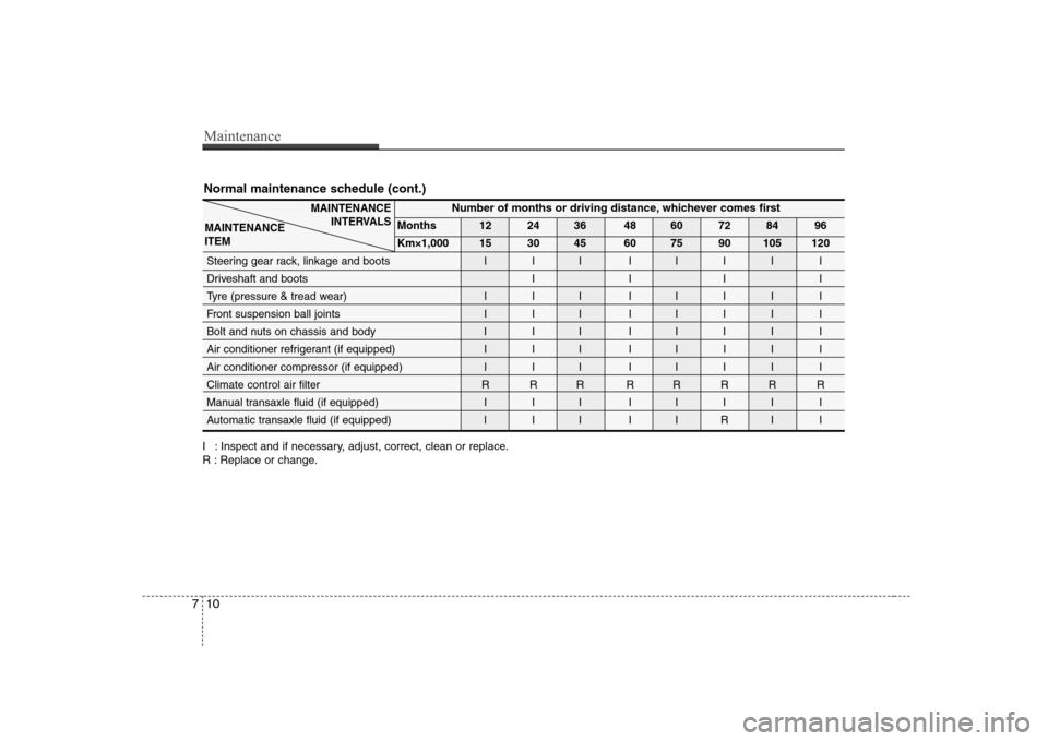
Normal maintenance schedule (cont.)
I : Inspect and if necessary, adjust, correct, clean or replace.
R : Replace or change.
Number of months or driving distance, whichever comes first
Months 12 24 36 48 60 72 84 96
Km×1,000 15 30 45 60 75 90 105 120
Steering gear rack, linkage and boots I I I I I I I I
Driveshaft and boots I I I I
Tyre (pressure & tread wear) I I I I I I I I
Front suspension ball joints I I I I I I I I
Bolt and nuts on chassis and body I I I I I I I I
Air conditioner refrigerant (if equipped) I I I I I I I I
Air conditioner compressor (if equipped) I I I I I I I I
Climate control air filter R R R R R R R R
Manual transaxle fluid (if equipped) I I I I I I I I
Automatic transaxle fluid (if equipped)
III IIRI I
MAINTENANCE INTERVALS
MAINTENANCE ITEM
Page 236 of 308
711
Maintenance
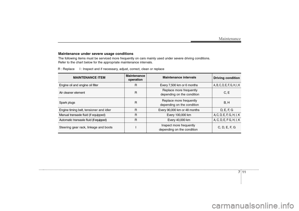
Maintenance under severe usage conditions
The following items must be serviced more frequently on cars mainly used under severe driving conditions.
Refer to the chart below for the appropriate maintenance intervals.
R : Replace I : Inspect and if necessary, adjust, correct, clean or replaceEngine oil and engine oil filter R Every 7,500 km or 6 months
A, B, C, D, E, F, G, H, I, K
Air cleaner element R C, E
Spark plugs R B, H
Engine timing belt, tensioner and idler R Every 90,000 km or 48 months D, E, F, G
Manual transaxle fluid (if equipped)
REvery 100,000 km A, C, D, E, F, G, H, I, K
Automatic transaxle fluid (if equipped)R Every 40,000 kmA, C, D, E, F G, H, I, K
Steering gear rack, linkage and boots I C, D, E, F, G
MAINTENANCE ITEMMaintenance
operation Maintenance intervals
Driving condition
Replace more frequently
depending on the condition
Inspect more frequently
depending on the condition Replace more frequently
depending on the condition
Page 237 of 308

Maintenance
12
7
Severe driving conditions
A : Repeated short distance driving
B : Extensive idling
C : Driving in dusty, rough roads
D : Driving in areas using salt or other corrosive
materials or in very cold weather
E : Driving in sandy areas F : More than 50 % driving in heavy city traffic during hot
weather above 32°C
G : Driving in mountainous areas.
H : Towing a trailer
I : Driving for patrol car, taxi, commercial car or vehicle tow- ing
J : Driving over 140 km/h
K : Driving over 170 km/h
Front suspension ball joints I C, D, E, F, G
Disc brakes and pads, calipers and rotors I C, D, E, G, H
Hand brake I C, D, G, H
Driveshaft and boots I C, D, E, F, I, H, K
Climate control air filter R C, E
MAINTENANCE ITEMMaintenance
operation Maintenance intervals
Driving condition
Inspect more frequently
depending on the condition
Inspect more frequently
depending on the condition
Inspect more frequently
depending on the condition
Inspect more frequently
depending on the condition
Replace more frequently
depending on the condition
Page 240 of 308

715
Maintenance
Manual transaxle fluid (if equipped)
Inspect the manual transaxle fluid
according to the maintenance schedule.
✽✽NOTICE
If the oil level is low, check for possible
leaks before adding oil. Do not overfill.
Automatic transaxle fluid (if equipped)
The fluid level should be in the "HOT"
range of the dipstick, after the engine
and transaxle are at normal operating
temperature. Check the automatic
transaxle fluid level with the engine run-
ning and the transaxle in neutral, with the
hand brake properly applied. Brake hoses and lines
Visually check for proper installation,
chafing, cracks, deterioration and any
leakage. Replace any deteriorated or
damaged parts immediately. Brake fluid
Check brake fluid level in the brake fluid
reservoir. The level should be between
“MIN” and “MAX” marks on the side of
the reservoir. Use only hydraulic brake
fluid conforming to DOT 3 or DOT 4. Hand brake
Inspect the hand brake system including
the hand brake lever and cables. For
detailed service procedures, refer to the
Shop Manual.
Brake pads, calipers and rotors
Check the pads for excessive wear, discs
for run out and wear, and calipers for fluid
leakage. Suspension mounting bolts
Check the suspension connections for
looseness or damage. Retighten to the
specified torque.
Steering gear box, linkage &
boots/lower arm ball joint
With the vehicle stopped and engine off,
check for excessive free-play in the
steering wheel.
Check the linkage for bends or damage.
Check the dust boots and ball joints for
deterioration, cracks, or damage.
Replace any damaged parts. Drive shafts and boots
Check the drive shafts, boots and clamps
for cracks, deterioration, or damage.
Replace any damaged parts and, if nec-
essary, repack the grease.
Air conditioning refrigerant (if equipped)
Check the air conditioning lines and con-
nections for leakage and damage. Check
air conditioning performance according
to the relevant shop manual if necessary.
Page 271 of 308
Maintenance
46
7
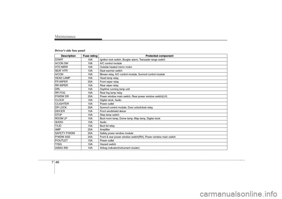
Driver's side fuse panel
Description Fuse rating Protected component
START 10A Ignition lock switch, Burglar alarm, Transaxle range switch
A/CON SW 10A A/C control module
HTD MIRR 10A Outside heated mirror motor
SEAT HTR 15A Seat warmer switch
A/CON 10A Blower relay, A/C control module, Sunroof control module
HEAD LAMP 10A Head lamp relay
FR WIPER 25A Front wiper relay
RR WIPER 15A Rear wiper relay
DRL 15A Daytime running lamp unit
RR FOG 10A Rear fog lamp relay
P/WDW DR 25A Power window main switch, Rear power window switch(LH)
CLOCK 10A Digital clock, Audio
C/LIGHTER 15A Power outlet
DR LOCK 20A Sunroof control module, Door unlock/lock relay
DEICER 15A Front windshield deicer
STOP 15A Stop lamp switch
ROOM LP 15A Boot room lamp, Dome lamp, Map lamp, Digital clock
AUDIO 15A Audio
T/LID 15A Boot lid relay
AMP 25A Amplifier
SAFETY P/WDW 25A Safety power window module
P/WDW ASS 25A Front & rear power window switch(RH), Power window main switch
P/OUTLET 15A Power outlet
T/SIG 10A Hazard switch
A/BAG IND 10A Airbag indicator(instrument cluster)
Page 278 of 308
753
Maintenance
4. Remove the bulb by pulling it straightout.
5. Insert a new bulb in the socket.
6. Reassemble the socket and the lens part.
7. Connect the bulb electrical connector.
8. Reinstall the light assembly to the body of the vehicle.
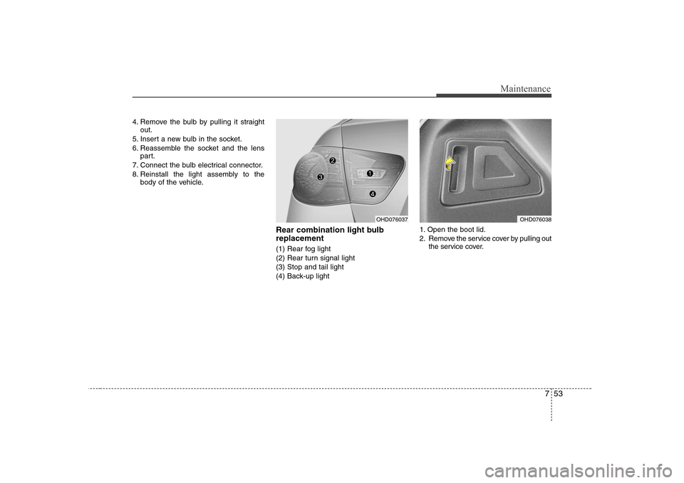
Rear combination light bulb replacement
(1) Rear fog light
(2) Rear turn signal light(3) Stop and tail light
(4) Back-up light 1. Open the boot lid.
2. Remove the service cover by pulling out
the service cover.
OHD076037OHD076038