coolant temperature Hyundai Getz 2007 User Guide
[x] Cancel search | Manufacturer: HYUNDAI, Model Year: 2007, Model line: Getz, Model: Hyundai Getz 2007Pages: 463, PDF Size: 11.14 MB
Page 211 of 463
6- 16 DO-IT-YOURSELF MAINTENANCE
WARNING:
The cooling fan is controlled by en- gine coolant temperature and maysometimes operate even when the engine is not running. Use extreme caution when working near theblades of the cooling fan, so that you are not injured by a rotating fan blade. As the engine coolant temper-ature decreases, the fan will auto- matically shut off. This is a normal condition.!
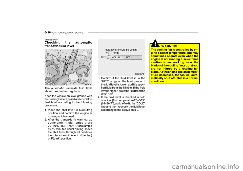
G110D02TB-GAT Checking the automatic transaxle fluid level
C090A03FC
Fluid level should be within "HOT" range
HTB164 3. Confirm if the fluid level is in the
“HOT” range on the level gauge. If the fluid level is lower, add the speci- fied fluid from the fill hole. If the fluid level is higher, drain the fluid from thedrain hole.
4. If the fluid level is checked in cold
condition[fluid temperature 20~30°C(68~86°F)], add the fluid to the “COLD” line and then recheck the fluid level according to the above step 2.
The automatic transaxle fluid levelshould be checked regularly. Keep the vehicle on level ground with the parking brake applied and check thefluid level according to the following procedure.
1. Place the shift lever in N(neutral)
position and confirm the engine is running at idle speed.
2. After the transaxle is warmed up sufficiently [fluid temperature70~80°C (158~176°F)], for exampleby 10 minutes usual driving, move the shift lever through all positions then place the shift lever in N(neutral)or P(park) position.
Page 221 of 463
6- 26 DO-IT-YOURSELF MAINTENANCE
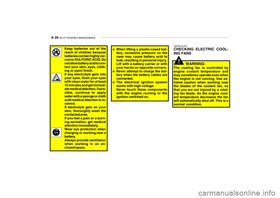
G220A01A-AAT CHECKING ELECTRIC COOL- ING FANS
WARNING:
The cooling fan is controlled by engine coolant temperature andmay sometimes operate even when the engine is not running. Use ex- treme caution when working nearthe blades of the coolant fan, so that you are not injured by a rotat- ing fan blade. As the engine cool-ant temperature decreases the fan will automatically shut off. This is a normal condition.
!
Keep batteries out of the reach of children becausebatteries contain highly cor- rosive SULFURIC ACID. Do not allow battery acid to con-tact your skin, eyes, cloth- ing or paint finish. If any electrolyte gets intoyour eyes, flush your eyes with clean water for at least 15 minutes and get immedi-ate medical attention. If pos- sible, continue to apply water with a sponge or clothuntil medical attention is re- ceived. If electrolyte gets on yourskin, thoroughly wash the contacted area. If you feel a pain or a burn-ing sensation, get medical attention immediately. Wear eye protection whencharging or working near a battery. Always provide ventilationwhen working in an en- closed space.o When lifting a plastic-cased bat- tery, excessive pressure on the case may cause battery acid toleak, resulting in personal injury. Lift with a battery carrier or with your hands on opposite corners.
o Never attempt to charge the bat- tery when the battery cables areconnected.
o The electrical ignition system works with high voltage.Never touch these componentswith the engine running or the ignition switched on.
Page 222 of 463
DO-IT-YOURSELF MAINTENANCE 6- 27
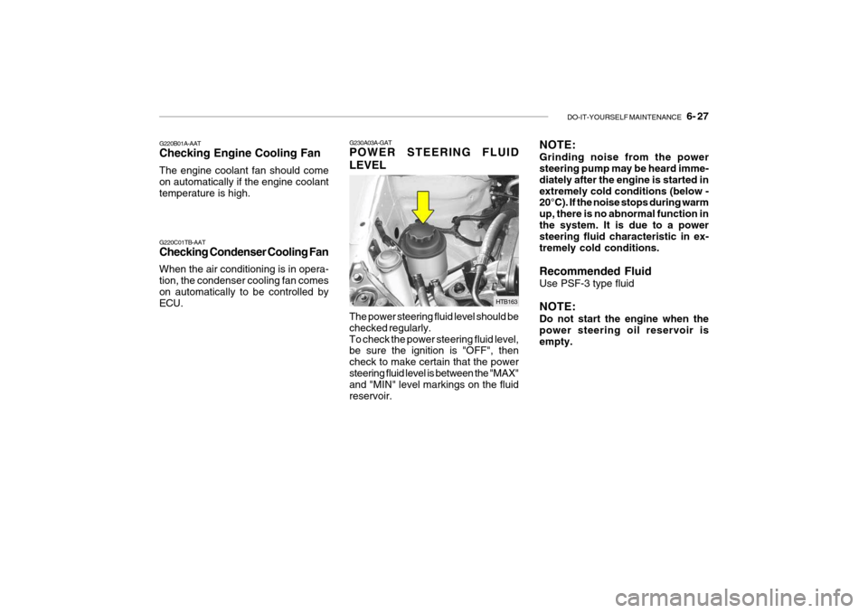
NOTE: Grinding noise from the power steering pump may be heard imme- diately after the engine is started inextremely cold conditions (below - 20°C). If the noise stops during warm up, there is no abnormal function inthe system. It is due to a power steering fluid characteristic in ex- tremely cold conditions. Recommended Fluid Use PSF-3 type fluid NOTE: Do not start the engine when the power steering oil reservoir is empty.G230A03A-GAT POWER STEERING FLUID LEVEL The power steering fluid level should be checked regularly.To check the power steering fluid level, be sure the ignition is "OFF", then check to make certain that the powersteering fluid level is between the "MAX" and "MIN" level markings on the fluid reservoir. HTB163
G220B01A-AAT Checking Engine Cooling Fan The engine coolant fan should come on automatically if the engine coolanttemperature is high. G220C01TB-AAT Checking Condenser Cooling Fan When the air conditioning is in opera- tion, the condenser cooling fan comes on automatically to be controlled by
ECU.
Page 236 of 463
7- 2 EMISSION CONTROL SYSTEMS
H010A01A-GAT
EMISSION CONTROL SYSTEM (If Installed)
Your Hyundai is equipped with an
emission control system to meet all requirements of the Emission prohibi- tion rules of your province.
There are three emission control sys-
tems which are as follows.
1) Crankcase emission control sys-
tem
2) Evaporative emission control sys- tem
3) Exhaust emission control system
In order to assure the proper function
of the emission control systems, it is recommended that you have your carinspected and maintained by an au- thorized Hyundai dealer in accordance with the maintenance schedule in thismanual. H010B01A-AAT
1. Crankcase Emission Control
System
The positive crankcase ventilation
system is employed to prevent airpollution caused by blow-by gases being emitted from the crankcase. This system supplies fresh air to thecrankcase through the air intake hose. Inside the crankcase, the fresh air mixes with blow-by gases, which thenpass through the PCV valve and into the induction system.
H010C02E-GAT
2. Evaporative Emission Control
System
The Evaporative Emission Control
System is designed to prevent fuel vapors from escaping into the atmo-sphere. Canister
While the engine is inoperative, fuel
vapors generated inside the fuel tank are absorbed and stored in the canis- ter. When the engine is running, the fuel vapors absorbed in the canister are drawn into the induction system through the purge control solenoid valve. Purge Control Solenoid Valve (PCSV)
The purge control solenoid valve is
controlled by the Engine Control Mod- ule (ECM); when the engine coolanttemperature is low during idling, the PCSV closes so that evaporated fuel is not taken into the engine. After theengine warms-up during ordinary driv- ing, the PCSV opens so as to intro- duce evaporated fuel to the engine. H010D01A-AAT
3. Exhaust Emission Control
System
The exhaust emission control system is a highly effective system whichcontrols exhaust emission while main- taining good vehicle performance.
TBENG_7.P65 6/14/2005, 3:31 PM
2
Page 251 of 463

INDEX 10- 3
D Day/Night inside rearview mirror ................................. 1-76
Defrosting / Defogging ................................................ 1-91
Digital clock ................................................................ 1-66
Door Door locks ................................................................ 1-7 Locking, unlocking front doors with a key ................ 1-7
Locking from the inside ............................................ 1-8
Locking from the outside .......................................... 1-8
Drink Holder ................................................................ 1-68
Drive Belts .................................................................. 6-22
Driving
Economical driving .................................................. 2-15
Smooth corneri ng ..................................................... 2-16
Winter driving ........................................................... 2-16
E Electronic stability program (ESP) ..............................2-14
Emission Contro l System ............................................ 7-2
Engine
Before starting the engine ........................................ 2-3Compartment ............................................................ 6-2
Coolant .................................................................... 6-10
Coolant temperature gauge ......................................1-54
If the engine overheats ............................................. 3-4
Number ..................................................................... 8-2
Oil ............................................................................. 6-7Starting ..................................................................... 2-3
Engine Exhaust Can Be Dangerous ............................ 2-2 FFog Light
Front ........................................................................ 1-65
Rear ......................................................................... 1-66
Folding the outside rearview mirror .............................1-75
Front Seats
Adjustable front seats .............................................. 1-13
Adjustable headrests ............................................... 1-14
Adjusting seat forward and rearward ........................1-13
Adjusting seatback angle .. ......................................1-13
Lumbar support control ............................................ 1-15
Seat cushion height adjustment .............................. 1-16
Seat warmer ............................................................ 1-20
Fuel
Capacity ................................................................... 9-2
Gauge ...................................................................... 1-55
recommendations ...................................................... 1-2
Fuel Filler Lid
Remote release ....................................................... 1-78
Fuses ......................................................................... 6-23
Fuse Panel description ............................................... 6-36
GGeneral Checks ........................................................... 6-5
Glove Box .................................................................. 1-73
Page 266 of 463

YOUR VEHICLE AT A GLANCE
F10
B255A01TB-EAT INDICATOR SYMBOLS ON THE INSTRUMENT PANEL * A detail explanations of these items will be found on page 1-46.
SRS (Airbag) Service Reminder Indicator ABS Service Reminder Indicator Turn Signal Indicator Lights High Beam Indicator Light Low Oil Pressure Warning Light Parking Brake/Brake Fluid Level Warning Light Charging System Warning LightTail Gate Open Warning Light Door Open (Ajar) Warning Light and Chime
Low Fuel Level Warning Light Malfunction Indicator Light Seat Belt Warning Light
O/D OFF Indicator (Automatic transaxle only)
Electric Power Steering System (EPS)Warning Light
Diesel Pre-heat Indicator Light (Diesel only)
Fuel Filter Warning Light (Diesel only)
Immobilizer Warning Light
Passenger's Front Airbag OFFIndicator Light
Electronic Stability Program Indicator Lights (If Installed)
Engine Coolant Temperature Indicator
Page 309 of 463

FEATURES OF YOUR HYUNDAI 1- 43
1. Tail Gate Open Warning Light
2. Immobiliser Warning Indicator Light
3. Tachometer
4. Turn Signal Indicator Light
5. Automatic Transaxle Position Indicator Light
(Not all models)
6. Fuel Gauge
7. Odometer/Trip Odometer
8. Speedometer
9. Malfunction Indicator Light (MIL)
10. Diesel Pre-heat Indicator Light (Diesel only)
11. High Beam Indicator Light
12. Engine Coolant Temperature Indicator Light
13. Parking Brake/Brake Fluid Level Warning Light 14. Door Open (Ajar) Warning Light
15. Passenger' s Front Airbag OFF Indicator Light
(Not all models)
16. SRS (Airbag) Warning Light (Not all models)
17. Low Fuel Warning Light
18. Electronic Stability Program (ESP) Indicator Light (Not all models)
19. ABS Warning Light
20. Fuel Filter Warning Light (Diesel only)
21. Seat Belt Warning Light
22. Oil Pressure Warning Light
23. Charging System Warning Light
24. Overdrive off Indicator Light (Auto T/A only)
Page 311 of 463

FEATURES OF YOUR HYUNDAI 1- 45
1. Hatch back door Open Warning Light
2. Immobiliser Warning Indicator Light
3. Tachometer
4. Turn Signal Indicator Light
5. Automatic Transaxle Position Indicator Light
(Not all models)
6. Odometer/Trip Odometer
7. Fuel Gauge
8. Trip Computer (Not all models)
9. Speedometer
10. Malfunction Indicator Light (MIL)
11. Diesel Pre-heat Indicator Light (Diesel only)
12. High Beam Indicator Light
13. Engine Coolant Temperature Indicator Light 14. Parking Brake/Brake Fluid Level Warning Light
15. Door Open (Ajar) Warning Light
16. Passenger' s Front Airbag OFF Indicator Light
(Not all models)
17. SRS (Airbag) Warning Light (Not all models)
18. Low Fuel Warning Light
19. Electronic Stability Program (ESP) Indicator Light (Not all models)
20. ABS Warning Light
21. Fuel Filter Warning Light (Diesel only)
22. Seat Belt Warning Light
23. Oil Pressure Warning Light
24. Charging System Warning Light
25. Overdrive Off Indcator Light (Auto T/A only)
Page 318 of 463
1- 52 FEATURES OF YOUR HYUNDAI
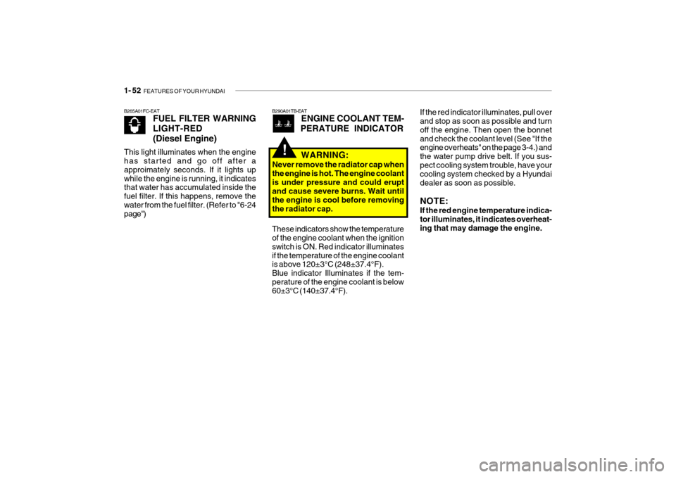
If the red indicator illuminates, pull over and stop as soon as possible and turn off the engine. Then open the bonnetand check the coolant level (See "If the engine overheats" on the page 3-4.) and the water pump drive belt. If you sus-pect cooling system trouble, have your cooling system checked by a Hyundai dealer as soon as possible. NOTE: If the red engine temperature indica- tor illuminates, it indicates overheat-ing that may damage the engine.
B265A01FC-EAT
FUEL FILTER WARNING LIGHT-RED(Diesel Engine)
This light illuminates when the engine has started and go off after a approimately seconds. If it lights upwhile the engine is running, it indicates that water has accumulated inside the fuel filter. If this happens, remove thewater from the fuel filter. (Refer to "6-24 page")B290A01TB-EAT ENGINE COOLANT TEM-
PERATURE INDICATOR
WARNING:
Never remove the radiator cap when the engine is hot. The engine coolantis under pressure and could erupt and cause severe burns. Wait until the engine is cool before removingthe radiator cap.
!
These indicators show the temperature of the engine coolant when the ignition switch is ON. Red indicator illuminatesif the temperature of the engine coolant is above 120±3°C (248±37.4°F). Blue indicator Illuminates if the tem-perature of the engine coolant is below 60±3°C (140±37.4°F).
Page 386 of 463
3- 4 WHAT TO DO IN AN EMERGENCY
!
!
D030A02TB-EAT IF THE ENGINE OVERHEATS If the temperature gauge indicates overheating:
1. Pull off the road and stop as soon as
it is safe to do so.
2. Place the gear selector lever in "P" (automatic), or neutral (manual transaxle) and set the parking brake.If the air conditioning is on, turn it off.
3. If coolant is running out under the car
or steam is coming out from underthe bonnet stop the engine. Do not open the bonnet until the coolant has stopped running or the steaming hasstopped. If there is no visible loss of coolant and no steam, leave the engine running and check to be surethe engine cooling fan is operating. If the fan is not running, turn the engine off.
4. Check to see if the water pump drive belt is missing. If it is not missing,check to see that it is tight. If thedrive belt seems to be satisfactory, check for coolant leaking from the radiator, hoses or under the car. (Ifthe air conditioning had been in use, it is normal for cold water to be draining from it). WARNING:
Whilst the engine is running, keep hands and clothing away from mov- ing parts such as the fan and drivebelts to prevent injury.
7. Switch ON the main beam
headlamps before carefully remov-ing the jumper cables in the reverseorder of attachment. Once the jumper cables have been removed, switch "OFF" the main beamheadlamps.
CAUTION:
If the jump cable is incorrectly in-stalled, damage to the vehicle elec- trical system may occur, in particu- lar the electronic components suchas the Fuel Injection system com- puter and the Automatic transaxle computer. The battery must neverbe disconnected whilst the engine is running.
!
WARNING (Diesel only):
Never work on injection system with engine running or within 30 sec- onds after shutting off engine. Highpressure pump, rail, injectors and high pressure pipes are subject to high pressure even after the enginestopped. The fuel jet produced by fuel leaks may cause serious in- jury, if it touches the body. Peopleusing pacemakers should not move closer than 30cm etc. to the ECU or wiring harness within the engineroom while engine is running, since the high currents in the Common Rail system produce considerablemagnetic fields.