wiring Hyundai Getz 2007 User Guide
[x] Cancel search | Manufacturer: HYUNDAI, Model Year: 2007, Model line: Getz, Model: Hyundai Getz 2007Pages: 463, PDF Size: 11.14 MB
Page 329 of 463

FEATURES OF YOUR HYUNDAI 1- 63
B500D01TG-GAT POWER OUTLET (If installed)
These supply 12V electric power to operate electric accessories or equip- ment only when the key is in the "ON" or "ACC" position.
!
CAUTION:
o Use when the engine is running and remove a plug from the power outlet after using the electric ap- pliance. Using when the engine stops or remaining the electricappliance with plugged in for many hours may cause the battery to be discharged.
o Do not use the power outlet to connect electric accessories orequipment other than those de-signed to operate on 12 volts.
o Some electronic devices can cause
electronic interference whenplugged into the power outlet. These devices may cause exces- sive audio noise and malfunctionsin other electronic systems or de- vices used in your vehicle.
B500D01TB-D
!
Do not hold the cigar lighter at the depressed position which may result in damage to the vehicle wiring or anelectrical fire. If it is necessary to replace the ciga- rette lighter, use only a genuine Hyundaireplacement part.
CAUTION:
Do not use electric accessories orequipment other than the Hyundai genuine parts in the socket.
Page 386 of 463
3- 4 WHAT TO DO IN AN EMERGENCY
!
!
D030A02TB-EAT IF THE ENGINE OVERHEATS If the temperature gauge indicates overheating:
1. Pull off the road and stop as soon as
it is safe to do so.
2. Place the gear selector lever in "P" (automatic), or neutral (manual transaxle) and set the parking brake.If the air conditioning is on, turn it off.
3. If coolant is running out under the car
or steam is coming out from underthe bonnet stop the engine. Do not open the bonnet until the coolant has stopped running or the steaming hasstopped. If there is no visible loss of coolant and no steam, leave the engine running and check to be surethe engine cooling fan is operating. If the fan is not running, turn the engine off.
4. Check to see if the water pump drive belt is missing. If it is not missing,check to see that it is tight. If thedrive belt seems to be satisfactory, check for coolant leaking from the radiator, hoses or under the car. (Ifthe air conditioning had been in use, it is normal for cold water to be draining from it). WARNING:
Whilst the engine is running, keep hands and clothing away from mov- ing parts such as the fan and drivebelts to prevent injury.
7. Switch ON the main beam
headlamps before carefully remov-ing the jumper cables in the reverseorder of attachment. Once the jumper cables have been removed, switch "OFF" the main beamheadlamps.
CAUTION:
If the jump cable is incorrectly in-stalled, damage to the vehicle elec- trical system may occur, in particu- lar the electronic components suchas the Fuel Injection system com- puter and the Automatic transaxle computer. The battery must neverbe disconnected whilst the engine is running.
!
WARNING (Diesel only):
Never work on injection system with engine running or within 30 sec- onds after shutting off engine. Highpressure pump, rail, injectors and high pressure pipes are subject to high pressure even after the enginestopped. The fuel jet produced by fuel leaks may cause serious in- jury, if it touches the body. Peopleusing pacemakers should not move closer than 30cm etc. to the ECU or wiring harness within the engineroom while engine is running, since the high currents in the Common Rail system produce considerablemagnetic fields.
Page 408 of 463

VEHICLE MAINTENANCE REQUIREMENTS 5- 7
!
6ZF060A1-A
EXPLANATION OF SCHEDULED MAINTENANCE ITEMS
F060M01A-AAT
o Engine oil and filter
The engine oil and filter should be changed at the intervals specified inthe maintenance schedule. If the car is being driven in severe conditions, more frequent oil and filter changesare required. F060B01A-AAT
o Drive belts
Inspect all drive belts for evidence of cuts, cracks, excessive wear or oilsaturation and replace if necessary. Drive belts should be checked peri- odically for proper tension and ad-justed as necessary. F060C01A-GAT
o Fuel filter
A clogged filter can limit the speed at
which the vehicle may be driven, dam- age the emission system and cause hard starting. If an excessive amountof foreign matter accumulates in the fuel tank, the filter may require re- placement more frequently.
After installing a new filter, run the
engine for several minutes, and checkfor leaks at the connections.
F060D01TB-EAT
o Fuel lines, fuel hoses and con- nections
Check the fuel lines, fuel hoses and
connections for leakage and damage. Replace any damaged or leaking parts immediately. WARNING (Diesel only):
Never work on injection systemwith engine running or within 30 seconds after shutting off engine.High pressure pump, rail, injectors and high pressure pipes are sub- jected to high pressure even afterthe engine has been switched off. The fuel jet produced by fuel leaks may cause serious injury, if it con-tacts with the body. People using pacemakers should not move closer than 30cm to the ECU orwiring harness within the engine room with the engine running, since the high currents in the CommonRail system produce considerable magnetic fields.
Page 427 of 463
6- 16 DO-IT-YOURSELF MAINTENANCE
if it touch the body. People using pacemakers should not move than 30cm closer to the ECU or wiringharness within the engine room while engine is running, since the high currents in the Common Rail systemproduce considerable magnetic fields.
!
CAUTION:
The automatic transaxle unit is a precision engineered assembly and correct operation is dependant uponthe exclusion of dirt and lint from the unit. Therefore, it is imperative that only lint free cloth (eg nylon) is usedfor wiping the dipstick and that the area around the dipstick is thor- oughly clean prior to level checkingor adding fluid. Fluid Capacity The total fluid capacity of the transaxle unit is 6.1 litres.
!
!
C090A03FC
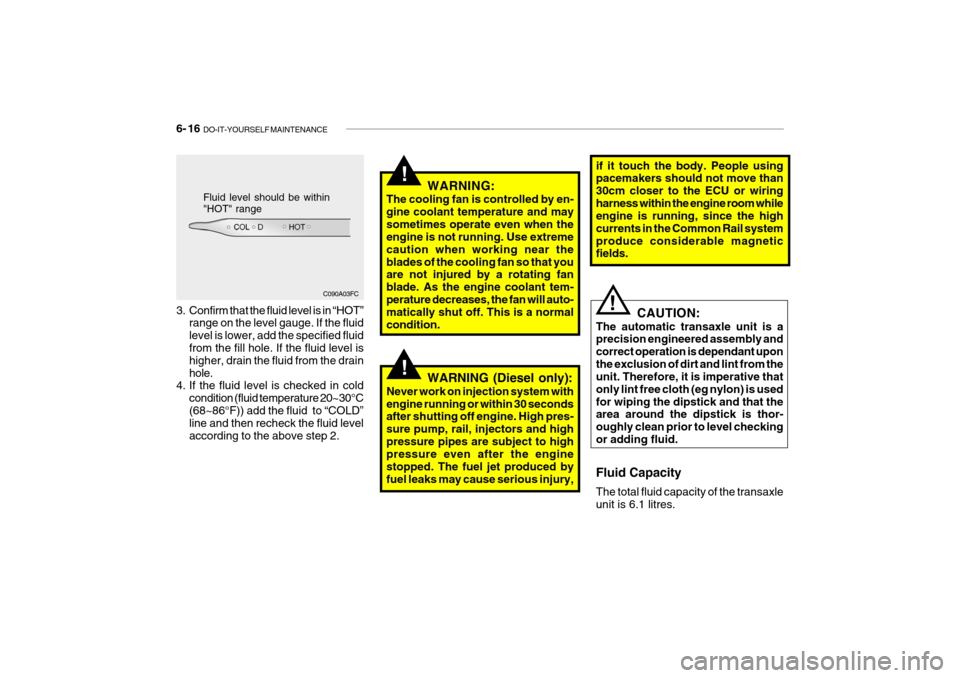
Fluid level should be within "HOT" range
3. Confirm that the fluid level is in “HOT” range on the level gauge. If the fluid level is lower, add the specified fluid from the fill hole. If the fluid level is higher, drain the fluid from the drainhole.
4. If the fluid level is checked in cold
condition (fluid temperature 20~30°C(68~86°F)) add the fluid to “COLD” line and then recheck the fluid level according to the above step 2. WARNING:
The cooling fan is controlled by en-gine coolant temperature and maysometimes operate even when the engine is not running. Use extreme caution when working near theblades of the cooling fan so that you are not injured by a rotating fan blade. As the engine coolant tem-perature decreases, the fan will auto- matically shut off. This is a normal condition.
WARNING (Diesel only):
Never work on injection system withengine running or within 30 seconds after shutting off engine. High pres- sure pump, rail, injectors and highpressure pipes are subject to high pressure even after the engine stopped. The fuel jet produced byfuel leaks may cause serious injury,
Page 430 of 463

DO-IT-YOURSELF MAINTENANCE 6- 19
B145A02TB-EAT CHANGING THE POLLEN FIL-
TER (In Front of evaporator unit)(Not all models) The pollen filter is located in front of the evaporator unit behind the glove box. It operates to decrease pollutants fromentering the car and to filter the air.
1. Remove the adjusting pins on both
sides of the glove box to open half the glove box.
HTB290-D
SG140D1-E Off Season Maintenance The air conditioning must be run for ten minutes or so weekly during periodswhen the system would not normally be used to ensure that the compressor and seals are lubricated. If this precautionis not observed the compressor seals may become stuck to the compressor shaft and damaged when the system isnext used resulting in a loss of refriger- ant and damage to the compressor.
3. Remove the filter cover to push theupside of the filter cover.
HTB291-D
2. Remove the cable and the wiring from the filter cover.
HTB292-D
Page 432 of 463
DO-IT-YOURSELF MAINTENANCE 6- 21
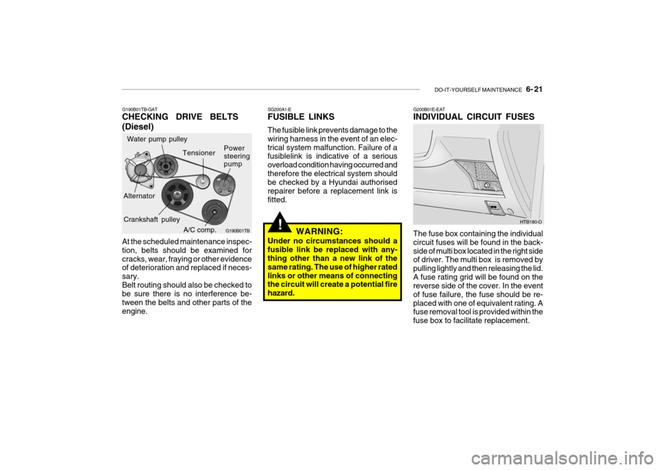
G190B01TB-GAT CHECKING DRIVE BELTS (Diesel) At the scheduled maintenance inspec- tion, belts should be examined forcracks, wear, fraying or other evidence of deterioration and replaced if neces- sary.Belt routing should also be checked to be sure there is no interference be- tween the belts and other parts of theengine.
!
SG200A1-E FUSIBLE LINKS The fusible link prevents damage to the wiring harness in the event of an elec-trical system malfunction. Failure of a fusiblelink is indicative of a serious overload condition having occurred andtherefore the electrical system should be checked by a Hyundai authorised repairer before a replacement link isfitted.
WARNING:
Under no circumstances should afusible link be replaced with any- thing other than a new link of the same rating. The use of higher ratedlinks or other means of connecting the circuit will create a potential fire hazard.G200B01E-EAT INDIVIDUAL CIRCUIT FUSES The fuse box containing the individual circuit fuses will be found in the back-side of multi box located in the right side of driver. The multi box is removed by pulling lightly and then releasing the lid.A fuse rating grid will be found on the reverse side of the cover. In the event of fuse failure, the fuse should be re-placed with one of equivalent rating. A fuse removal tool is provided within the fuse box to facilitate replacement. HTB180-D
A/C comp.
Water pump pulley
G190B01TB
Alternator Power steering pump
Tensioner
Crankshaft pulley