maintenance schedule Hyundai Getz 2009 User Guide
[x] Cancel search | Manufacturer: HYUNDAI, Model Year: 2009, Model line: Getz, Model: Hyundai Getz 2009Pages: 254, PDF Size: 7.8 MB
Page 209 of 254

6- 14 DO-IT-YOURSELF MAINTENANCE
WARNING:
It is always better to check the transaxle oil level when the engine is cool or cold. If the engine is hot, you should exercise great cautionto avoid burning yourself on hot engine or exhaust parts.!
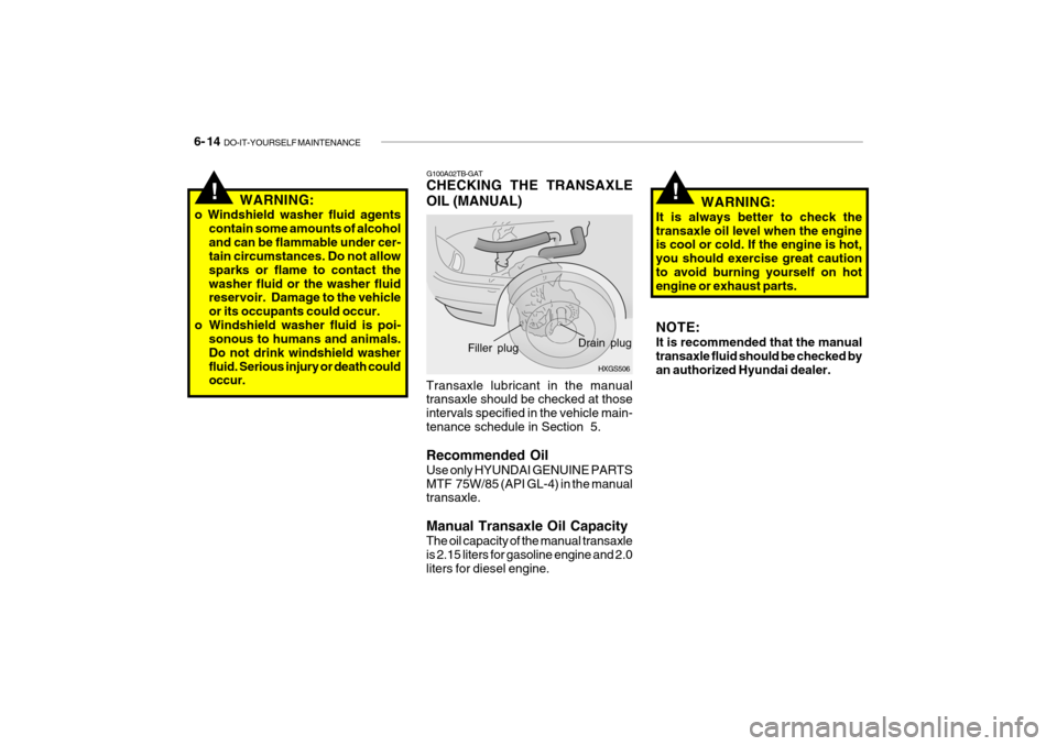
G100A02TB-GAT CHECKING THE TRANSAXLE OIL (MANUAL)
HXGS506
Drain plug
Filler plug
Transaxle lubricant in the manual transaxle should be checked at those intervals specified in the vehicle main-tenance schedule in Section 5. Recommended Oil Use only HYUNDAI GENUINE PARTS MTF 75W/85 (API GL-4) in the manual transaxle. Manual Transaxle Oil Capacity The oil capacity of the manual transaxle is 2.15 liters for gasoline engine and 2.0 liters for diesel engine.
!WARNING:
o Windshield washer fluid agents contain some amounts of alcohol and can be flammable under cer- tain circumstances. Do not allow sparks or flame to contact thewasher fluid or the washer fluid reservoir. Damage to the vehicle or its occupants could occur.
o Windshield washer fluid is poi- sonous to humans and animals.Do not drink windshield washerfluid. Serious injury or death could occur. NOTE: It is recommended that the manual transaxle fluid should be checked by an authorized Hyundai dealer.
Page 210 of 254

DO-IT-YOURSELF MAINTENANCE 6- 15
G110A02E-AAT CHECKING THE TRANSAXLE FLUID (AUTOMATIC) Transaxle fluid in the automatic transaxle should be checked at those intervals specified in the vehicle main-tenance schedule in Section 5. NOTE: Automatic transaxle fluid is basi- cally a red color. As driving distance increases, the fluid color turns dark- ish red gradually. It is normal condi-tion and you should not judge the need to replace based upon the changing color.You must replace the automatic transaxle fluid in accordance with intervals specified in the vehiclemaintenance schedule in section 5. G110B04A-AAT Recommended Fluid Your Hyundai automatic transaxle is specially designed to operate withHyundai Genuine ATF SP-III, DIA- MOND ATF SP-III, SK ATF SP-III or other brands approved by Hyundai MotorCo., Damage caused by a nonspecified fluid is not covered by your new vehicle limited warranty.G110C01TB-GAT Transaxle Fluid Capacity The fluid capacity of the automatic transaxle is 6.1 liters.
WARNING:
The transaxle fluid level should bechecked when the engine is at nor-mal operating temperature. This means that the engine, radiator, exhaust system etc., are very hot.Exercise great care not to burn your- self during this procedure.
!
Page 212 of 254

DO-IT-YOURSELF MAINTENANCE 6- 17
WARNING (DIESEL ONLY):
Never work on injection system with engine running or within 30 secondsafter shutting off engine. High pres- sure pump, rail, injectors and high pressure pipes are subjected to highpressure even after the engine has been switched off. The fuel jet pro- duced by fuel leaks may cause seri-ous injury, if it contacts with the body. People using pacemakers should not move closer than 30cm tothe ECU or wiring harness within the engine room with the engine run- ning, since the high currents in the Common Rail system produce con- siderable magnetic fields.
!
G120A01A-AAT CHECKING THE BRAKES G120B01A-AATChecking the Brake Fluid Level
!
CAUTION:
Because brakes are essential to the safe operation of the car, it is sug- gested that they be checked and inspected by your Hyundai dealer.The brakes should be checked and inspected for wear at those inter- vals specified in the vehicle mainte-nance schedule in Section 5. WARNING:
Use caution when handling brakefluid. It can damage your vision if it gets into your eyes. It will also dam- age your vehicle's paint if spilledon it and not removed immediately.!
G120C02A-AAT Recommended Brake Fluid Use only hydraulic brake fluid con- forming to DOT 3 or DOT 4 specifica- tions in your braking system. Follow the instructions printed on the con-tainer.
Page 217 of 254

6- 22 DO-IT-YOURSELF MAINTENANCE
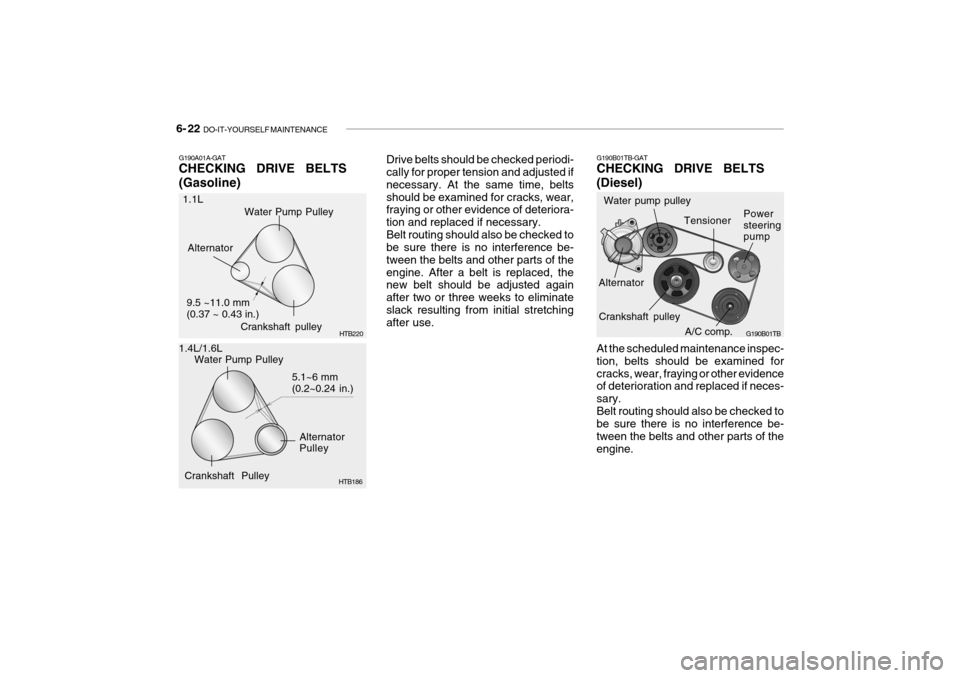
Drive belts should be checked periodi- cally for proper tension and adjusted if necessary. At the same time, beltsshould be examined for cracks, wear, fraying or other evidence of deteriora- tion and replaced if necessary.Belt routing should also be checked to be sure there is no interference be- tween the belts and other parts of theengine. After a belt is replaced, the new belt should be adjusted again after two or three weeks to eliminateslack resulting from initial stretching after use. G190B01TB-GAT CHECKING DRIVE BELTS (Diesel)
A/C comp.
Water pump pulley
G190B01TB
Alternator Power steering pump
At the scheduled maintenance inspec- tion, belts should be examined forcracks, wear, fraying or other evidence of deterioration and replaced if neces- sary.Belt routing should also be checked to be sure there is no interference be- tween the belts and other parts of theengine.Water Pump Pulley
Alternator Pulley
Crankshaft Pulley 5.1~6 mm(0.2~0.24 in.)
G190A01A-GAT CHECKING DRIVE BELTS (Gasoline)
HTB186
1.1L
1.4L/1.6L Crankshaft pulley
Alternator
HTB220
Water Pump Pulley
9.5 ~11.0 mm (0.37 ~ 0.43 in.)Tensioner
Crankshaft pulley
Page 236 of 254

7- 2 EMISSION CONTROL SYSTEMS
H010A01A-GAT
EMISSION CONTROL SYSTEM (If Installed)
Your Hyundai is equipped with an
emission control system to meet all requirements of the Emission prohibi- tion rules of your province.
There are three emission control sys-
tems which are as follows.
1) Crankcase emission control sys-
tem
2) Evaporative emission control sys- tem
3) Exhaust emission control system
In order to assure the proper function
of the emission control systems, it is recommended that you have your carinspected and maintained by an au- thorized Hyundai dealer in accordance with the maintenance schedule in thismanual. H010B01A-AAT
1. Crankcase Emission Control
System
The positive crankcase ventilation
system is employed to prevent airpollution caused by blow-by gases being emitted from the crankcase. This system supplies fresh air to thecrankcase through the air intake hose. Inside the crankcase, the fresh air mixes with blow-by gases, which thenpass through the PCV valve and into the induction system.
H010C02E-GAT
2. Evaporative Emission Control
System
The Evaporative Emission Control
System is designed to prevent fuel vapors from escaping into the atmo-sphere. Canister
While the engine is inoperative, fuel
vapors generated inside the fuel tank are absorbed and stored in the canis- ter. When the engine is running, the fuel vapors absorbed in the canister are drawn into the induction system through the purge control solenoid valve. Purge Control Solenoid Valve (PCSV)
The purge control solenoid valve is
controlled by the Engine Control Mod- ule (ECM); when the engine coolanttemperature is low during idling, the PCSV closes so that evaporated fuel is not taken into the engine. After theengine warms-up during ordinary driv- ing, the PCSV opens so as to intro- duce evaporated fuel to the engine. H010D01A-AAT
3. Exhaust Emission Control
System
The exhaust emission control system is a highly effective system whichcontrols exhaust emission while main- taining good vehicle performance.
Page 252 of 254

10- 4 INDEX
H Hazard Warning System ............................................. 1-64
Headlight Aiming Adjustm ent ...................................... 6-31
Headlight Leveling Device S ystem .............................1-68
Headlight flasher ......................................................... 1-60
Headlight switch ......................................................... 1-59
Heating and cooling control ........................................ 1-86
Heating and Ventilation ............................................... 1-87
Air flow control ......................................................... 1-88
Air intake control ..................................................... 1-88
Bi-level heating ........................................................ 1-91
Fan speed control .................................................... 1-87
Temperature control ................................................. 1-90
High-Mounted Rear Stop Light.................................... 1-76
Hood Release ............................................................. 1-77
How to use luggage room ........................................... 1-80
Horn ............................................................................ 1-84
IIgnition Switch ............................................................. 2-3
Immobilizer System ..................................................... 1-5
Instrument Cluster and Indicator light ......................... 1-44
IInterior Light Interior light .............................................................. 1-71
Map light .................................................................. 1-71
Intermittent Wiper ....................................................... 1-63
JJump Starting .............................................................. 3-3 K
Key .............................................................................. 1-4
If you lose your keys .............................................. 3-14
Positions ................................................................... 2-4
Keyless entry system ................................................. 1-11
LLane change si gnal ..................................................... 1-59
Lubrication Chart .......................................................... 9-4
Luggage Net ............................................................... 1-82
Luggage Board ............................................................ 1-82
Luggage Under Tray ................................................... 1-81
Lumbar Support Control .............................................. 1-16
MMaintenance Intervals Explanation of scheduled maintenance items................................................................................. 5-8
Maintenance under severe usage conditions ............ 5-7
Scheduled maintenance ............................................ 5-4
Service requirements ................................................ 5-2
Mirrors
Day-night inside rearview ......... ................................1-75
Outside rearview mirror heater .................................1-75
O
Odometer .................................................................... 1-56
Outside rear view mirror
Electric type ............................................................ 1-74
Manual type ............................................................. 1-73