fuel cap Hyundai Grandeur 2003 Owner's Manual
[x] Cancel search | Manufacturer: HYUNDAI, Model Year: 2003, Model line: Grandeur, Model: Hyundai Grandeur 2003Pages: 235, PDF Size: 14.25 MB
Page 60 of 235

1- 46 FEATURES OF YOUR HYUNDAI
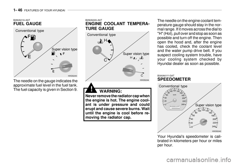
B300A01Y-GAT SPEEDOMETER Your Hyundai's speedometer is cali- brated in kilometers per hour or miles per hour. HXGS242
Conventional type
Super vision type
B280A01A-AAT FUEL GAUGE
B290A02A-AATENGINE COOLANT TEMPERA- TURE GAUGE
WARNING:
Never remove the radiator cap when the engine is hot. The engine cool-ant is under pressure and could erupt and cause severe burns. Wait until the engine is cool before re-moving the radiator cap.
HXGS243
HXGS244
The needle on the gauge indicates theapproximate fuel level in the fuel tank. The fuel capacity is given in Section 9. Conventional type
Conventional type
Super vision type
Super vision type
The needle on the engine coolant tem- perature gauge should stay in the nor- mal range. If it moves across the dial to"H" (Hot), pull over and stop as soon as possible and turn off the engine. Then open the hood and, after the enginehas cooled, check the coolant level and the water pump drive belt. If you suspect cooling system trouble, haveyour cooling system checked by Hyundai dealer as soon as possible.
!
Page 82 of 235

1- 68 FEATURES OF YOUR HYUNDAI
HXGS255
WARNING:
Gasoline vapors are dangerous. Before refueling, always stop the engine and never allow sparks or open flames near the filler area. Ifyou need to replace the filler cap, use a genuine Hyundai replacement part.If you open the fuel filler cap during high ambient temperatures, a slight "pressure sound" may be heard.This is normal and not a cause for concern. Whenever you open the fuel fillercap, turn it slowly.
HXGS207
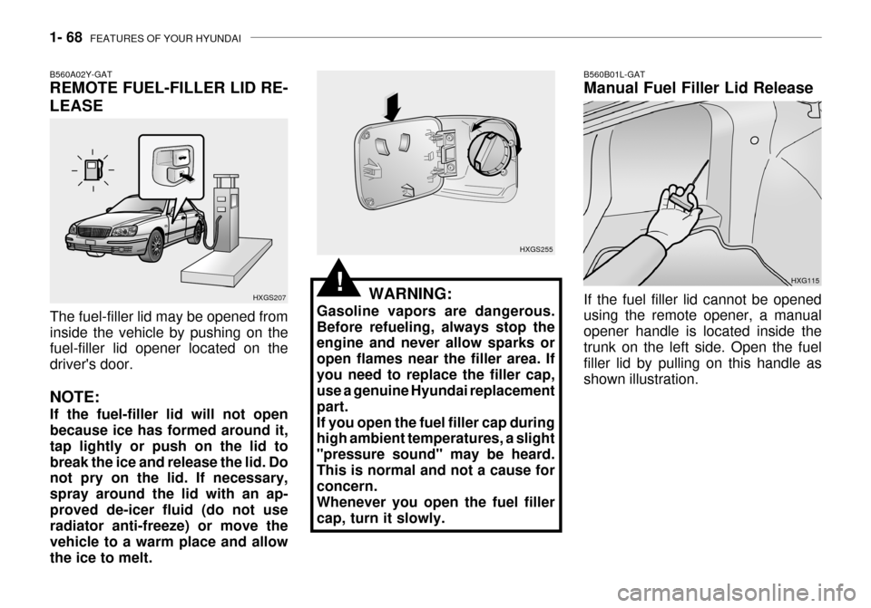
B560A02Y-GAT REMOTE FUEL-FILLER LID RE- LEASE
The fuel-filler lid may be opened from inside the vehicle by pushing on the fuel-filler lid opener located on the driver's door. NOTE: If the fuel-filler lid will not open because ice has formed around it, tap lightly or push on the lid tobreak the ice and release the lid. Do not pry on the lid. If necessary, spray around the lid with an ap-proved de-icer fluid (do not use radiator anti-freeze) or move the vehicle to a warm place and allowthe ice to melt.
!HXG115
B560B01L-GAT Manual Fuel Filler Lid Release If the fuel filler lid cannot be opened using the remote opener, a manual opener handle is located inside thetrunk on the left side. Open the fuel filler lid by pulling on this handle as shown illustration.
Page 176 of 235

5- 4 VEHICLE MAINTENANCE REQUIREMENTS
NO.
1 2 3 4 5 6 7 8 9 DESCRIPTION
ENGINE CONTROL SYSTEM MAINTENANCE ENGINE OIL & FILTER (SG OR ABOVE) See Note (1)
DRIVE BELT 3.0 V6 / 3.5 V6 (ALT, P/STRG, A/CON) 2.5 V6 (AUTO-TENSIONER)
FUEL FILTER (MFI TYPE) FUEL LINES, FUEL HOSES & CONNECTIONS TIMING BELT VAPOR HOSE & FUEL FILLER CAP VACUUM & CRANKCASE VENTILATION HOSES AIR CLEANER FILTER SPARK PLUGS SPARK PLUGS (PLATINUM COATED)
F030A01A-GAT SCHEDULED MAINTENANCE The following maintenance services must be performed to assure good vehicle control and performance. Keep receipts for all vehicle services to protect your warranty. Where both mileage and time are shown, the frequency of service is determined by whichever occurs first.
F030B02L-GAT R :Replace I : Inspect and, after Inspection, clean, adjust, repair or replace if necessary.105 84
R I I I 120
96
R R I
R
I I I
R
90
72
R I I I
R
I I
R
75
60
R I I I
60 48
R II
R
I I I I
R
45
36
R I I I
30
24
R I I II I
R
15
12
R I I I
KILOMETERS X 1000 MONTHS
Note : (1) SF OR LOWER: EVERY 10,000 KM OR 6 MONTHS : "R"
(2) FOR EVERY 40,000KM : "R" (3) FOR EVERY 100,000KM : "R"
See Note (2) See Note (3)
Page 179 of 235

VEHICLE MAINTENANCE REQUIREMENTS 5- 7
F060A01A-AAT
EXPLANATION OF SCHEDULED MAINTENANCE ITEMS
F060M01A-AAT
o Engine Oil and Filter
The engine oil and filter should be changed at the intervals specified in the maintenance schedule. If the car is being driven in severe conditions,more frequent oil and filter changes are required. F060B01A-AAT
o Drive Belts
Inspect all drive belts for evidence of cuts, cracks, excessive wear or oil and replace if necessary. Drive beltsshould be checked periodically for proper tension and adjusted as nec- essary. After installing a new filter, run the
engine for several minutes, and checkfor leaks at the connections. Fuelfilters should be installed by trained technicians.
F060D01A-AAT
o Fuel Lines, Fuel Hoses and Connections
Check the fuel lines, fuel hoses and connections for leakage and damage.Have a trained technician replace any damaged or leaking parts immedi- ately. F060E01A-AAT
o Timing Belt Inspect all parts related to the timing belt for damage and deformation. Replace any damaged parts immedi- ately. F060G01A-AAT
o Vapor Hose and Fuel Filler Cap The vapor hose and fuel filler cap should be inspected at those inter- vals specified in the maintenance schedule. Make sure that a new va-por hose or fuel filler cap is correctly replaced. F060F01A-AAT
o Vacuum, Crankcase Ventila-
tion Hoses
Inspect the surface of hoses for evi- dence of heat and/or mechanical dam-age. Hard and brittle rubber, crack- ing, tears, cuts, abrasions, and ex- cessive swelling indicate deteriora-tion. Particular attention should be paid to examine those hose surfaces nearest to high heat sources, such asthe exhaust manifold.Inspect the hose routing to assurethat the hoses do not come in contact with any heat source, sharp edges or moving component which might causeheat damage or mechanical wear. Inspect all hose connections, such as clamps and couplings, to make surethey are secure, and that no leaks are present. Hoses should be replaced immediately if there is any evidenceof deterioration or damage.
F060C01A-AAT
o Fuel Filter
A clogged filter can limit the speed atwhich the vehicle may be driven, dam- age the emission system and cause hard starting. If an excessive amountof foreign matter accumulates in the fuel tank, the filter may require re- placement more frequently.
Page 187 of 235

6- 6 DO-IT-YOURSELF MAINTENANCE
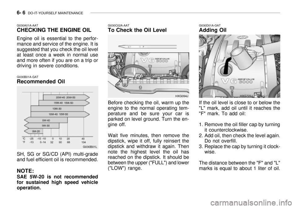
G030A01A-AAT CHECKING THE ENGINE OIL Engine oil is essential to the perfor- mance and service of the engine. It is suggested that you check the oil level at least once a week in normal useand more often if you are on a trip or driving in severe conditions. G030B01A-GAT Recommended Oil
G030B01L
SH, SG or SG/CD (API) multi-grade and fuel efficient oil is recommended. NOTE: SAE 5W-20 is not recommended for sustained high speed vehicle operation.G030C02A-AAT
To Check the Oil Level
Before checking the oil, warm up the
engine to the normal operating tem- perature and be sure your car is parked on level ground. Turn the en-gine off.
Wait five minutes, then remove the
dipstick, wipe it off, fully reinsert thedipstick and withdraw it again. Thennote the highest level the oil has reached on the dipstick. It should be between the upper ("FULL") and lower("LOW") range. HXG094J
G030D01A-GAT
Adding Oil
If the oil level is close to or below the
"L" mark, add oil until it reaches the "F" mark. To add oil:
1. Remove the oil filler cap by turning it counterclockwise.
2. Add oil, then check the level again. Do not overfill.
3. Replace the cap by turning it clock- wise.
The distance between the "F" and "L"
marks is equal to about 1 liter of oil.
HXG722J
Page 218 of 235

7- 2 EMISSION CONTROL SYSTEMS
H010A01A-GAT
EMISSION CONTROL SYSTEM (If Installed)
Your Hyundai is equipped with an
emission control system to meet all requirements of the Emission prohibi-tion rules of your province.
There are three emission control sys-
tems which are as follows.
1) Crankcase emission control sys-
tem
2) Evaporative emission control sys- tem
3) Exhaust emission control system
In order to assure the proper function
of the emission control systems, it is recommended that you have your car inspected and maintained by an au-thorized Hyundai dealer in accordance with the maintenance schedule in this manual. H010B01A-AAT
1. Crankcase Emission Control
System
The positive crankcase ventilation
system is employed to prevent airpollution caused by blow-by gasesbeing emitted from the crankcase. This system supplies fresh air to the crankcase through the air intake hose.Inside the crankcase, the fresh air mixes with blow-by gases, which then pass through the PCV valve and intothe induction system.
H010C02Y-GAT
2. Evaporative Emission
Control System
The Evaporative Emission Control
System is designed to prevent fuel vapors from escaping into the atmo- sphere. Canister
While the engine is inoperative, fuel
vapors generated inside the fuel tank are absorbed and stored in the canis- ter. When the engine is running, the fuel vapors absorbed in the canisterare drawn into the induction system through the purge control solenoidvalve. Purge Control Solenoid Valve
The purge control solenoid valve is
controlled by the ECM; when the en- gine coolant temperature is low, and during idling, it closes, so that evapo- rated fuel is not taken into the surgetank. After engine warm-up, during ordinary driving, it opens so as to introduce evaporated fuel to the surgetank.
H010D01A-AAT
3. Exhaust Emission Control
System
The exhaust emission control system
is a highly effective system whichcontrols exhaust emission while main- taining good vehicle performance.
H010E01Y-GAT
EGR System
This system helps control nitrogen
oxides by recirculating a part of the exhaust gas into the engine, therebyreducing cylinder combustion tem- perature.
Page 226 of 235

9- 2 VEHICLE SPECIFICATIONS
3.0 V6
J010A02L-GAT MEASUREMENT
4,875 (191.8) 1,800 (70.86)
1,420 (55.9)
2,750 (108.2) 1,540 (60.6)
1,530 (60.23)
Overall lengthOverall widthOverall height Wheel base Wheel tread
Front
Rear
Type Wheel free play Rack strokeOil pump type Rack and pinion0 ~ 30 mm (0 ~ 1.18 in.) 146 mm (5.74 in.) Vane type
J060A01L-GAT FUEL SYSTEM
J020A01L-GAT POWER STEERING
Fuel tank capacity 70 Liter J030A03L-GAT TIRE
205/65 R15 94V 205/60 R16 96V
StandardOption
J050A01L-GAT BRAKE
Dual hydraulic with brake booster Ventilated discSolid disc Cable operated on rear wheel
Type Front brake typeRear brake type Parking brake
Item Battery
Alternator 120A (13.5V)
2.5 V6
110A (13.5V)
J040A02L-GAT ELECTRICAL
MF 68AH (MF)
3.5 V6
mm (in.)
Page 231 of 235

INDEX 10- 3
D Defrosting / Defogging .............................................. 1-83
Door Door locks ................................................................ 1-6
Door courtesy light ................................................. 1-71
Locking and unlocking front doors with a key ......... 1-6
Drink Holder .................................................. 1-57 ~ 1-58
Drive Belts ...................................................... 6-18, 6-21
Driving Economical driving ..................................... 2-14 ~ 2-15
Smooth cornering ................................................... 2-15
Winter driving ......................................................... 2-16
E Emission Control System ................................. 7-1 ~ 7-3
Engine
Before starting the engi ne ....................................... 2-3
Compartment ................................................... 6-1~6-3
Coolant ......................................................... 6-8 ~ 6-10
Coolant temperature gauge ................................... 1-46
If the engine overheats ............................................ 3-4
Number .................................................................... 8-2
Oil ............................................................................. 6-6
Starting ..................................................................... 2-4
Engine Exhaust Can Be Dangerous ........................... 2-2F
Fan Speed Control .......................................... 1-79, 1-88 Fog Light
Front ....................................................................... 1-48
Rear ........................................................... 1-48 ~ 1-49
Front Seats
Adjustable front seats ............................................ 1-11
Adjustable headrests .............................................. 1-13
Adjusting seat forward and rearward ......... 1-11 ~ 1-12
Adjusting seatback angle .............. .........................1-12
Lumbar support control ............... ........................... 1-13
Seat cushion height adjustment............................ 1-14
Seat warmer ........................................................... 1-17
Fuel
Capacity ................................................................... 9-2
Gauge .................................................................... 1-46
recommendations ..................................................... 1-2
Fuel Filler Lid
Remote release ...................................................... 1-68
Manual ................................................................... 1-68
Fuses ............................................................ 6-21 ~ 6-22 G General Checks .......................................................... 6-5
Glove Box ................................................................. 1-62