warning Hyundai H-1 (Grand Starex) 2003 Owner's Guide
[x] Cancel search | Manufacturer: HYUNDAI, Model Year: 2003, Model line: H-1 (Grand Starex), Model: Hyundai H-1 (Grand Starex) 2003Pages: 173, PDF Size: 3.68 MB
Page 41 of 173
INSTRUMENTS & CONTROLS
INSTRUMENTS & CONTROLS INSTRUMENTS & CONTROLS
INSTRUMENTS & CONTROLS
INSTRUMENTS & CONTROLS
2-2
C020A02P-1
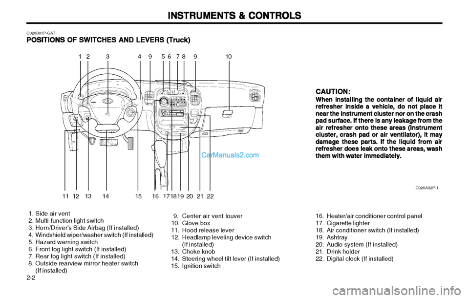
1. Side air vent
2. Multi-function light switch
3. Horn/Driver's Side Airbag (If installed)
4. Windshield wiper/washer switch (If installed)
5. Hazard warning switch
6. Front fog light switch (If installed)
7. Rear fog light switch (If installed)
8. Outside rearview mirror heater switch (If installed) 9. Center air vent louver
10. Glove box
11. Hood release lever
12. Headlamp leveling device switch (If installed)
13. Choke knob
14. Steering wheel tilt lever (If installed)
15. Ignition switch 16. Heater/air conditioner control panel
17. Cigarette lighter
18. Air conditioner switch (If installed)
19. Ashtray
20. Audio system (If installed)
21. Drink holder
22. Digital clock (If installed)CAUTION:
CAUTION: CAUTION:
CAUTION:
CAUTION:
When installing the container of liquid air
When installing the container of liquid air When installing the container of liquid air
When installing the container of liquid air
When installing the container of liquid air
refresher inside a vehicle, do not place it
refresher inside a vehicle, do not place it refresher inside a vehicle, do not place it
refresher inside a vehicle, do not place it
refresher inside a vehicle, do not place it
near the instrument cluster nor on the crash
near the instrument cluster nor on the crash near the instrument cluster nor on the crash
near the instrument cluster nor on the crash
near the instrument cluster nor on the crash
pad surface. If there is any leakage from the
pad surface. If there is any leakage from the pad surface. If there is any leakage from the
pad surface. If there is any leakage from the
pad surface. If there is any leakage from the
air refresher onto these areas (Instrument
air refresher onto these areas (Instrument air refresher onto these areas (Instrument
air refresher onto these areas (Instrument
air refresher onto these areas (Instrument
cluster, crash pad or air ventilator), it may
cluster, crash pad or air ventilator), it may cluster, crash pad or air ventilator), it may
cluster, crash pad or air ventilator), it may
cluster, crash pad or air ventilator), it may
damage these parts. If the liquid from air
damage these parts. If the liquid from air damage these parts. If the liquid from air
damage these parts. If the liquid from air
damage these parts. If the liquid from air
refresher does leak onto these areas, wash
refresher does leak onto these areas, wash refresher does leak onto these areas, wash
refresher does leak onto these areas, wash
refresher does leak onto these areas, wash
them with water immediately.
them with water immediately. them with water immediately.
them with water immediately.
them with water immediately.
11 39
5 1 0
12 4 6 9 78
C020B01P-GAT
POSITIONS OF SWITCHES AND LEVERS (T
POSITIONS OF SWITCHES AND LEVERS (T POSITIONS OF SWITCHES AND LEVERS (T
POSITIONS OF SWITCHES AND LEVERS (T
POSITIONS OF SWITCHES AND LEVERS (T ruck)
ruck) ruck)
ruck)
ruck)
13
12 14 16 15 17 18 19 20 21 22
Page 47 of 173
INSTRUMENTS & CONTROLS
INSTRUMENTS & CONTROLS INSTRUMENTS & CONTROLS
INSTRUMENTS & CONTROLS
INSTRUMENTS & CONTROLS
2-8 C130A04P-GAT
INDICATION AND WARNING LAMPS
INDICATION AND WARNING LAMPS INDICATION AND WARNING LAMPS
INDICATION AND WARNING LAMPS
INDICATION AND WARNING LAMPS
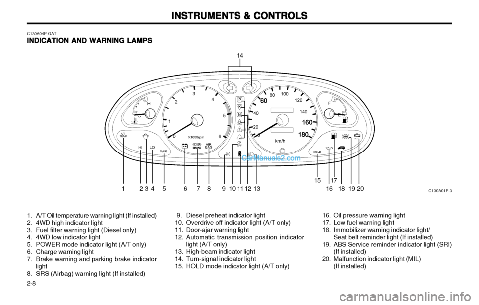
1. A/T Oil temperature warning light (If installed)
2. 4WD high indicator light
3. Fuel filter warning light (Diesel only)
4. 4WD low indicator light
5. POWER mode indicator light (A/T only)
6. Charge warning light
7. Brake warning and parking brake indicator
light
8. SRS (Airbag) warning light (If installed) 9. Diesel preheat indicator light
10. Overdrive off indicator light (A/T only)
11. Door-ajar warning light
12. Automatic transmission position indicator
light (A/T only)
13. High-beam indicator light
14. Turn-signal indicator light
15. HOLD mode indicator light (A/T only) 16. Oil pressure warning light
17. Low fuel warning light
18. Immobilizer warning indicator light/
Seat belt reminder light (If installed)
19. ABS Service reminder indicator light (SRI) (If installed)
20. Malfunction indicator light (MIL) (If installed)
2
C130A01P-3
14
13 678 1 618 19 20
17
12
111091 345
15
Page 48 of 173
2-9
INSTRUMENTS & CONTROLS
INSTRUMENTS & CONTROLS INSTRUMENTS & CONTROLS
INSTRUMENTS & CONTROLS
INSTRUMENTS & CONTROLS
C130B01P-GAT DOOR-AJAR WARNING
DOOR-AJAR WARNING DOOR-AJAR WARNING
DOOR-AJAR WARNING
DOOR-AJAR WARNING
LAMP-RED
LAMP-RED LAMP-RED
LAMP-RED
LAMP-RED
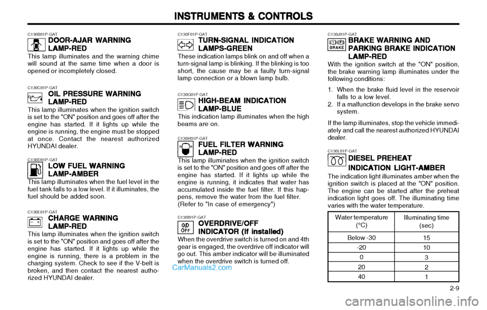
This lamp illuminates and the warning chime
will sound at the same time when a door is opened or incompletely closed.
C130F01P-GAT TURN-SIGNAL INDICATION
TURN-SIGNAL INDICATION TURN-SIGNAL INDICATION
TURN-SIGNAL INDICATION
TURN-SIGNAL INDICATION
LAMPS-GREEN
LAMPS-GREEN LAMPS-GREEN
LAMPS-GREEN
LAMPS-GREEN
These indication lamps blink on and off when a
turn-signal lamp is blinking. If the blinking is too short, the cause may be a faulty turn-signallamp connection or a blown lamp bulb.
C130G01P-GAT HIGH-BEAM INDICATION
HIGH-BEAM INDICATION HIGH-BEAM INDICATION
HIGH-BEAM INDICATION
HIGH-BEAM INDICATION
LAMP-BLUE
LAMP-BLUE LAMP-BLUE
LAMP-BLUE
LAMP-BLUE
This indication lamp illuminates when the high
beams are on.
C130H01P-GAT FUEL FILTER WARNING
FUEL FILTER WARNING FUEL FILTER WARNING
FUEL FILTER WARNING
FUEL FILTER WARNING
LAMP-RED
LAMP-RED LAMP-RED
LAMP-RED
LAMP-RED
This lamp illuminates when the ignition switch
is set to the "ON" position and goes off after the engine has started. If it lights up while theengine is running, it indicates that water hasaccumulated inside the fuel filter. If this hap-pens, remove the water from the fuel filter.
(Refer to "In case of emergency")
C130I01P-GAT OVERDRIVE/OFF
OVERDRIVE/OFF OVERDRIVE/OFF
OVERDRIVE/OFF
OVERDRIVE/OFF
INDICATOR (If installed)
INDICATOR (If installed) INDICATOR (If installed)
INDICATOR (If installed)
INDICATOR (If installed)
When the overdrive switch is turned on and 4th
gear is engaged, the overdrive off indicator will go out. This amber indicator will be illuminatedwhen the overdrive switch is turned off.
C130J01P-GAT BRAKE WARNING AND
BRAKE WARNING AND BRAKE WARNING AND
BRAKE WARNING AND
BRAKE WARNING AND
PARKING BRAKE INDICATION
PARKING BRAKE INDICATION PARKING BRAKE INDICATION
PARKING BRAKE INDICATION
PARKING BRAKE INDICATION
LAMP-RED
LAMP-RED LAMP-RED
LAMP-RED
LAMP-RED
With the ignition switch at the "ON" position,
the brake warning lamp illuminates under the following conditions:
1. When the brake fluid level in the reservoir falls to a low level.
2. If a malfunction develops in the brake servo system.
If the lamp illuminates, stop the vehicle immedi-
ately and call the nearest authorized HYUNDAI dealer.
C130C01P-GAT
OIL PRESSURE WARNING
OIL PRESSURE WARNING OIL PRESSURE WARNING
OIL PRESSURE WARNING
OIL PRESSURE WARNING
LAMP-RED
LAMP-RED LAMP-RED
LAMP-RED
LAMP-RED
This lamp illuminates when the ignition switch
is set to the "ON" position and goes off after theengine has started. If it lights up while theengine is running, the engine must be stoppedat once. Contact the nearest authorizedHYUNDAI dealer.
C130D01P-GAT LOW FUEL WARNING
LOW FUEL WARNING LOW FUEL WARNING
LOW FUEL WARNING
LOW FUEL WARNING
LAMP-AMBER
LAMP-AMBER LAMP-AMBER
LAMP-AMBER
LAMP-AMBER
This lamp illuminates when the fuel level in the
fuel tank falls to a low level. If it illuminates, the fuel should be added soon.
C130E01P-GAT CHARGE WARNING
CHARGE WARNING CHARGE WARNING
CHARGE WARNING
CHARGE WARNING
LAMP-RED
LAMP-RED LAMP-RED
LAMP-RED
LAMP-RED
This lamp illuminates when the ignition switch
is set to the "ON" position and goes off after the engine has started. If it lights up while theengine is running, there is a problem in thecharging system. Check to see if the V-belt isbroken, and then contact the nearest autho-rized HYUNDAI dealer.
C130L01P-GAT
DIESEL PREHEAT
DIESEL PREHEAT DIESEL PREHEAT
DIESEL PREHEAT
DIESEL PREHEAT
INDICATION LIGHT-AMBER
INDICATION LIGHT-AMBER INDICATION LIGHT-AMBER
INDICATION LIGHT-AMBER
INDICATION LIGHT-AMBER
The indication light illuminates amber when the
ignition switch is placed at the "ON" position. The engine can be started after the preheatindication light goes off. The illuminating timevaries with the water temperature.
Water temperature
(°C)
Below -30 -20
0
20 40 Illuminating time
(sec)
151032 1
Page 49 of 173
INSTRUMENTS & CONTROLS
INSTRUMENTS & CONTROLS INSTRUMENTS & CONTROLS
INSTRUMENTS & CONTROLS
INSTRUMENTS & CONTROLS
2-10 C130P01P-GAT
A/T (AUTOMATIC TRANSMIS-
A/T (AUTOMATIC TRANSMIS- A/T (AUTOMATIC TRANSMIS-
A/T (AUTOMATIC TRANSMIS-
A/T (AUTOMATIC TRANSMIS-
SION) OIL TEMPERATURE
SION) OIL TEMPERATURE SION) OIL TEMPERATURE
SION) OIL TEMPERATURE
SION) OIL TEMPERATURE
WARNING LIGHT
WARNING LIGHT WARNING LIGHT
WARNING LIGHT
WARNING LIGHT
(If installed)
(If installed) (If installed)
(If installed)
(If installed)
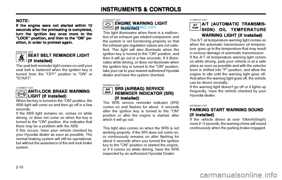
The A/T oil temperature warning light comes on when the automatic transmission oil tempera-ture goes up to the temperature that may resultin serious damage of automatic transmission. If the A/T oil temperature warning light comes on while driving, park your vehicle in at a safeplace as soon as possible and with the selectorlever is shifted into "P" position, and allow theengine to idle until the warning light goes off.And when the warning light goes off, the vehiclecan be driven normally. If the warning light doesn't go off or it lights up frequently, have the vehicle checked by yourHyundai dealer.
A/TA/T
A/TA/T
A/T
TEMPTEMP
TEMPTEMP
TEMP
NOTE:
NOTE: NOTE:
NOTE:
NOTE:
If the engine were not started within 10
If the engine were not started within 10 If the engine were not started within 10
If the engine were not started within 10
If the engine were not started within 10 seconds after the preheating is completed,
seconds after the preheating is completed, seconds after the preheating is completed,
seconds after the preheating is completed,
seconds after the preheating is completed,
turn the ignition key once more to the
turn the ignition key once more to the turn the ignition key once more to the
turn the ignition key once more to the
turn the ignition key once more to the
"LOCK" position, and then to the "ON" po-
"LOCK" position, and then to the "ON" po- "LOCK" position, and then to the "ON" po-
"LOCK" position, and then to the "ON" po-
"LOCK" position, and then to the "ON" po-
sition, in order to preheat again.
sition, in order to preheat again. sition, in order to preheat again.
sition, in order to preheat again.
sition, in order to preheat again. B260E02A-GAT
SEAT BELT REMINDER LIGHT
SEAT BELT REMINDER LIGHT SEAT BELT REMINDER LIGHT
SEAT BELT REMINDER LIGHT
SEAT BELT REMINDER LIGHT
(If installed)
(If installed) (If installed)
(If installed)
(If installed)
The seat belt reminder light comes on until your seat belt is fastened when the ignition key isturned from the "OFF" position to "ON" or"START". C130O01P-GAT
ENGINE WARNING LIGHT
ENGINE WARNING LIGHT ENGINE WARNING LIGHT
ENGINE WARNING LIGHT
ENGINE WARNING LIGHT
(If installed)
(If installed) (If installed)
(If installed)
(If installed)
This light illuminates when there is a malfunc-
tion of an exhaust gas related component, andthe system is not functioning properly so thatthe exhaust gas regulation values are not satis-fied. This light will also illuminate when theignition key is turned to the "ON" position, andthen it will go out in a few seconds. If it illumi-nates while driving, or does not illuminate whenthe ignition key is turned to the "ON" position,take your car to your nearest authorized Hyundaidealer and have the system checked.
B260B01S-GAT SRS (AIRBAG) SERVICE
SRS (AIRBAG) SERVICE SRS (AIRBAG) SERVICE
SRS (AIRBAG) SERVICE
SRS (AIRBAG) SERVICE
REMINDER INDICATOR
REMINDER INDICATOR REMINDER INDICATOR
REMINDER INDICATOR
REMINDER INDICATOR (SRI)
(SRI) (SRI)
(SRI)
(SRI)
(If installed)
(If installed) (If installed)
(If installed)
(If installed)
The SRS service reminder indicator (SRI)
comes on and flashes for about 6 secondsafter the ignition key is turned to the "ON"
position or after the engine is started, afterwhich it will go out.
This light also comes on when the SRS is not
working properly. If the SRI does not come on,or continuously remains on after flashing forabout 6 seconds when you turned the ignition
key to the "ON" position or started the engine,or if it comes on while driving, have the SRSinspected by an authorized Hyundai Dealer.
C130N01P-GAT
ANTI-LOCK BRAKE WARNING
ANTI-LOCK BRAKE WARNING ANTI-LOCK BRAKE WARNING
ANTI-LOCK BRAKE WARNING
ANTI-LOCK BRAKE WARNING
LIGHT (If installed)
LIGHT (If installed) LIGHT (If installed)
LIGHT (If installed)
LIGHT (If installed)
When the key is turned to the "ON" position, the
ABS light will come on and then go off in a fewseconds. If the ABS light remains on, comes on while
driving, or does not come on when the key isturned to the "ON" position, this indicates thatthere may be a problem with the ABS.
If this occurs, have your vehicle checked by
your Hyundai dealer as soon as possible. Thenormal braking system will still be operational,but without the assistance of the anti-lock brakesystem.
AIRAIR
AIRAIR
AIR
BAGBAG
BAGBAG
BAG
B270B02O-GATPARKING START WARNING SOUND
PARKING START WARNING SOUND PARKING START WARNING SOUND
PARKING START WARNING SOUND
PARKING START WARNING SOUND
(If installed)
(If installed) (If installed)
(If installed)
(If installed)
If the vehicle driven at over 10km/h(6mph) more 2~3 seconds, the warning chime will soundcontinuously when the parking brake engaged.
Page 54 of 173
2-15
INSTRUMENTS & CONTROLS
INSTRUMENTS & CONTROLS INSTRUMENTS & CONTROLS
INSTRUMENTS & CONTROLS
INSTRUMENTS & CONTROLS
B620A01S-AATFRONT DOOR EDGE WARNING LIGHT
FRONT DOOR EDGE WARNING LIGHT FRONT DOOR EDGE WARNING LIGHT
FRONT DOOR EDGE WARNING LIGHT
FRONT DOOR EDGE WARNING LIGHT
(If installed)
(If installed) (If installed)
(If installed)
(If installed)
C230A01P-GAT
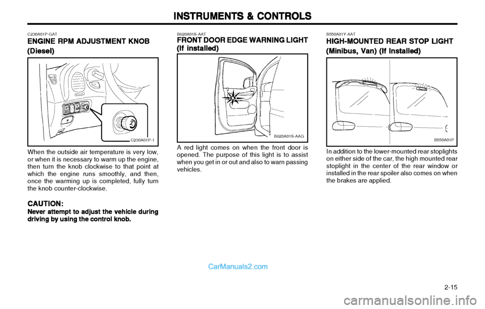
ENGINE RPM ADJUSTMENT KNOB
ENGINE RPM ADJUSTMENT KNOB ENGINE RPM ADJUSTMENT KNOB
ENGINE RPM ADJUSTMENT KNOB
ENGINE RPM ADJUSTMENT KNOB
(D(D
(D(D
(D iesel)
iesel) iesel)
iesel)
iesel)
C230A01P-1
When the outside air temperature is very low, or when it is necessary to warm up the engine,then turn the knob clockwise to that point atwhich the engine runs smoothly, and then,once the warming up is completed, fully turnthe knob counter-clockwise.
CAUTION:
CAUTION: CAUTION:
CAUTION:
CAUTION:
Never attempt to adjust the vehicle during
Never attempt to adjust the vehicle during Never attempt to adjust the vehicle during
Never attempt to adjust the vehicle during
Never attempt to adjust the vehicle during
driving by using the control knob.
driving by using the control knob. driving by using the control knob.
driving by using the control knob.
driving by using the control knob.B620A01S-AAG
A red light comes on when the front door is
opened. The purpose of this light is to assist when you get in or out and also to warn passing
vehicles. B550A01Y-AAT
HIGH-MOUNTED REAR STOP LIGHT
HIGH-MOUNTED REAR STOP LIGHT HIGH-MOUNTED REAR STOP LIGHT
HIGH-MOUNTED REAR STOP LIGHT
HIGH-MOUNTED REAR STOP LIGHT
(Minibus, Van) (If Installed)
(Minibus, Van) (If Installed) (Minibus, Van) (If Installed)
(Minibus, Van) (If Installed)
(Minibus, Van) (If Installed)B550A01P
In addition to the lower-mounted rear stoplights on either side of the car, the high mounted rearstoplight in the center of the rear window orinstalled in the rear spoiler also comes on whenthe brakes are applied.
Page 55 of 173
INSTRUMENTS & CONTROLS
INSTRUMENTS & CONTROLS INSTRUMENTS & CONTROLS
INSTRUMENTS & CONTROLS
INSTRUMENTS & CONTROLS
2-16 B380A01A-AAT
REAR WINDOW DEFROSTER SWITCH
REAR WINDOW DEFROSTER SWITCH REAR WINDOW DEFROSTER SWITCH
REAR WINDOW DEFROSTER SWITCH
REAR WINDOW DEFROSTER SWITCH
(If installed)
(If installed) (If installed)
(If installed)
(If installed)
B380A01A-AAG
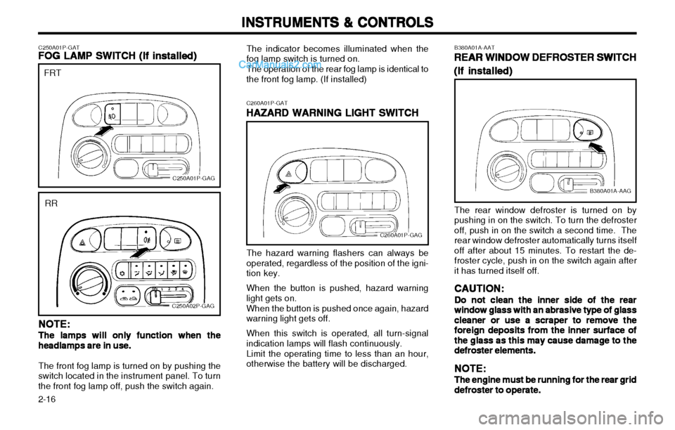
The rear window defroster is turned on by
pushing in on the switch. To turn the defrosteroff, push in on the switch a second time. The
rear window defroster automatically turns itselfoff after about 15 minutes. To restart the de-froster cycle, push in on the switch again after
it has turned itself off. CAUTION:
CAUTION: CAUTION:
CAUTION:
CAUTION:
Do not clean the inner side of the rear
Do not clean the inner side of the rear Do not clean the inner side of the rear
Do not clean the inner side of the rear
Do not clean the inner side of the rear
window glass with an
window glass with an window glass with an
window glass with an
window glass with an abrasive type of glass
abrasive type of glass abrasive type of glass
abrasive type of glass
abrasive type of glass
cleaner or use a scraper to remove the
cleaner or use a scraper to remove the cleaner or use a scraper to remove the
cleaner or use a scraper to remove the
cleaner or use a scraper to remove the
foreign deposits
foreign deposits foreign deposits
foreign deposits
foreign deposits from the inner surface of
from the inner surface of from the inner surface of
from the inner surface of
from the inner surface of
the glass as this may cause damage to the
the glass as this may cause damage to the the glass as this may cause damage to the
the glass as this may cause damage to the
the glass as this may cause damage to the
defroster
defroster defroster
defroster
defroster
elements.
elements. elements.
elements.
elements.
NOTE:
NOTE: NOTE:
NOTE:
NOTE:
The engine must be running for the rear grid
The engine must be running for the rear grid The engine must be running for the rear grid
The engine must be running for the rear grid
The engine must be running for the rear grid
defroster to operate.
defroster to operate. defroster to operate.
defroster to operate.
defroster to operate.
C260A01P-GAT
HAZARD WARNING LIGHT SWITCH
HAZARD WARNING LIGHT SWITCH HAZARD WARNING LIGHT SWITCH
HAZARD WARNING LIGHT SWITCH
HAZARD WARNING LIGHT SWITCHThe indicator becomes illuminated when thefog lamp switch is turned on. The operation of the rear fog lamp is identical to the front fog lamp. (If installed)
C260A01P-GAG
The hazard warning flashers can always be operated, regardless of the position of the igni-tion key. When the button is pushed, hazard warning light gets on. When the button is pushed once again, hazard warning light gets off. When this switch is operated, all turn-signal indication lamps will flash continuously. Limit the operating time to less than an hour, otherwise the battery will be discharged.
C250A01P-GAT
FOG LAMP SWITCH
FOG LAMP SWITCH FOG LAMP SWITCH
FOG LAMP SWITCH
FOG LAMP SWITCH
(If installed)
(If installed) (If installed)
(If installed)
(If installed)
C250A01P-GAG
FRT
C250A02P-GAG
RR
NOTE:
NOTE: NOTE:
NOTE:
NOTE:
The lamps will only function when the
The lamps will only function when the The lamps will only function when the
The lamps will only function when the
The lamps will only function when the headlamps are in use.
headlamps are in use. headlamps are in use.
headlamps are in use.
headlamps are in use.
The front fog lamp is turned on by pushing the
switch located in the instrument panel. To turn the front fog lamp off, push the switch again.
Page 58 of 173
2-19
INSTRUMENTS & CONTROLS
INSTRUMENTS & CONTROLS INSTRUMENTS & CONTROLS
INSTRUMENTS & CONTROLS
INSTRUMENTS & CONTROLS
B470A01S-AAT SUNSHADE (Minibus) (If installed)
SUNSHADE (Minibus) (If installed) SUNSHADE (Minibus) (If installed)
SUNSHADE (Minibus) (If installed)
SUNSHADE (Minibus) (If installed)
B470A01S-AAG
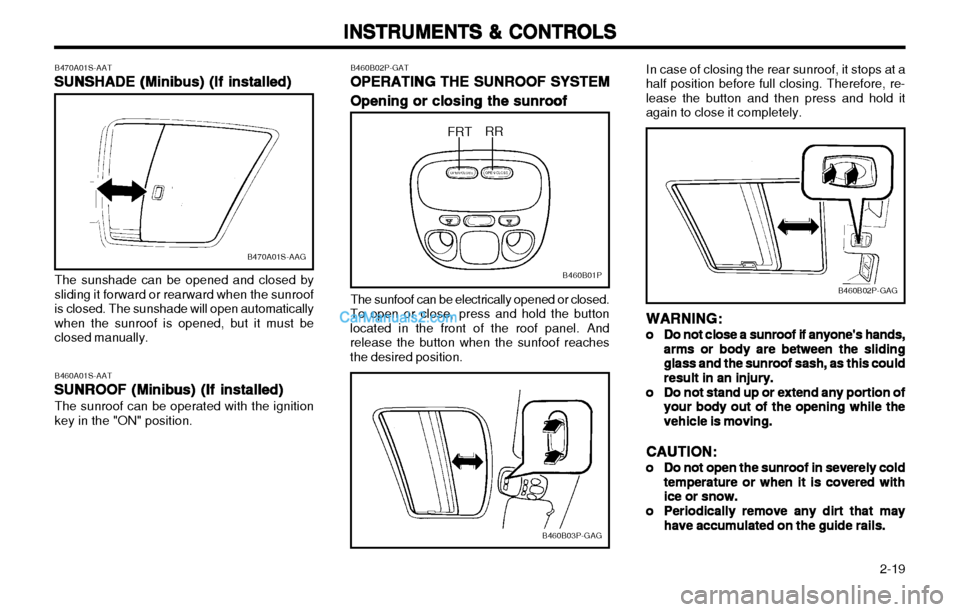
The sunshade can be opened and closed by
sliding it forward or rearward when the sunroof
is closed. The sunshade will open automaticallywhen the sunroof is opened, but it must beclosed manually. B460A01S-AAT
SUNROOF (Minibus) (If installed)
SUNROOF (Minibus) (If installed) SUNROOF (Minibus) (If installed)
SUNROOF (Minibus) (If installed)
SUNROOF (Minibus) (If installed)
The sunroof can be operated with the ignition
key in the "ON" position. B460B02P-GAT
OPERATING THE SUNROOF SYSTEM
OPERATING THE SUNROOF SYSTEM OPERATING THE SUNROOF SYSTEM
OPERATING THE SUNROOF SYSTEM
OPERATING THE SUNROOF SYSTEM
Opening or closing the sunroof
Opening or closing the sunroof Opening or closing the sunroof
Opening or closing the sunroof
Opening or closing the sunroofB460B01P
FRT RR
The sunfoof can be electrically opened or closed.
To open or close, press and hold the button located in the front of the roof panel. Andrelease the button when the sunfoof reachesthe desired position.
B460B03P-GAG
B460B02P-GAG
In case of closing the rear sunroof, it stops at a
half position before full closing. Therefore, re- lease the button and then press and hold itagain to close it completely.
WARNING:
WARNING: WARNING:
WARNING:
WARNING:
oo
oo
o Do not close a sunroof if anyone's hands,
Do not close a sunroof if anyone's hands, Do not close a sunroof if anyone's hands,
Do not close a sunroof if anyone's hands,
Do not close a sunroof if anyone's hands,
arms or body are between the sliding
arms or body are between the sliding arms or body are between the sliding
arms or body are between the sliding
arms or body are between the sliding
glass and the sunroof sash, as this could
glass and the sunroof sash, as this could glass and the sunroof sash, as this could
glass and the sunroof sash, as this could
glass and the sunroof sash, as this could
result in an injury.
result in an injury. result in an injury.
result in an injury.
result in an injury.
oo
oo
o Do not stand up or extend any portion of
Do not stand up or extend any portion of Do not stand up or extend any portion of
Do not stand up or extend any portion of
Do not stand up or extend any portion of
your body out of the opening while the
your body out of the opening while the your body out of the opening while the
your body out of the opening while the
your body out of the opening while the
vehicle is moving.
vehicle is moving. vehicle is moving.
vehicle is moving.
vehicle is moving.
CAUTION:
CAUTION: CAUTION:
CAUTION:
CAUTION:
oo
oo
o Do not open the sunroof in severely cold
Do not open the sunroof in severely cold Do not open the sunroof in severely cold
Do not open the sunroof in severely cold
Do not open the sunroof in severely cold
temperature or when it is covered with
temperature or when it is covered with temperature or when it is covered with
temperature or when it is covered with
temperature or when it is covered with
ice or snow.
ice or snow. ice or snow.
ice or snow.
ice or snow.
oo
oo
o Periodically remove any dirt that may
Periodically remove any dirt that may Periodically remove any dirt that may
Periodically remove any dirt that may
Periodically remove any dirt that may
have accumulated on the guide rails.
have accumulated on the guide rails. have accumulated on the guide rails.
have accumulated on the guide rails.
have accumulated on the guide rails.
Page 61 of 173
INSTRUMENTS & CONTROLS
INSTRUMENTS & CONTROLS INSTRUMENTS & CONTROLS
INSTRUMENTS & CONTROLS
INSTRUMENTS & CONTROLS
2-22 B510D01Y-AAT
OUTSIDE REARVIEW MIRROR HEAT-
OUTSIDE REARVIEW MIRROR HEAT- OUTSIDE REARVIEW MIRROR HEAT-
OUTSIDE REARVIEW MIRROR HEAT-
OUTSIDE REARVIEW MIRROR HEAT-
ER (If installed)
ER (If installed) ER (If installed)
ER (If installed)
ER (If installed)
B510D01Y-AAG
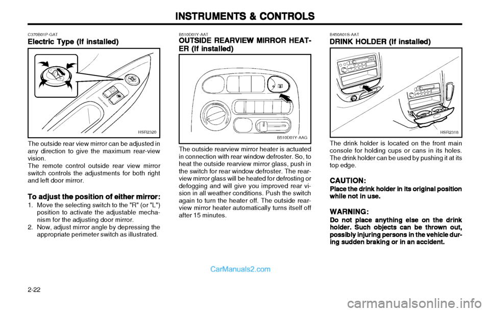
The outside rearview mirror heater is actuated
in connection with rear window defroster. So, toheat the outside rearview mirror glass, push inthe switch for rear window defroster. The rear-
view mirror glass will be heated for defrosting ordefogging and will give you improved rear vi-
sion in all weather conditions. Push the switch
again to turn the heater off. The outside rear-view mirror heater automatically turns itself offafter 15 minutes. B450A01S-AAT
DRINK HOLDER (If installed)
DRINK HOLDER (If installed) DRINK HOLDER (If installed)
DRINK HOLDER (If installed)
DRINK HOLDER (If installed)
The drink holder is located on the front mainconsole for holding cups or cans in its holes.
The drink holder can be used by pushing it at itstop edge. CAUTION:
CAUTION: CAUTION:
CAUTION:
CAUTION:
Place the drink holder in its original position
Place the drink holder in its original position Place the drink holder in its original position
Place the drink holder in its original position
Place the drink holder in its original position
while not in
while not in while not in
while not in
while not in
use.use.
use.use.
use.
WARNING:
WARNING: WARNING:
WARNING:
WARNING:
Do not place anything else on the drink
Do not place anything else on the drink Do not place anything else on the drink
Do not place anything else on the drink
Do not place anything else on the drink
holder. Such objects
holder. Such objects holder. Such objects
holder. Such objects
holder. Such objects can be thrown out,
can be thrown out, can be thrown out,
can be thrown out,
can be thrown out,
possibly injuring persons in the vehicle dur-
possibly injuring persons in the vehicle dur- possibly injuring persons in the vehicle dur-
possibly injuring persons in the vehicle dur-
possibly injuring persons in the vehicle dur-
ing sudden
ing sudden ing sudden
ing sudden
ing sudden braking or in an accident.
braking or in an accident. braking or in an accident.
braking or in an accident.
braking or in an accident.
C370B01P-GAT
Electric Type (If installed)
Electric Type (If installed) Electric Type (If installed)
Electric Type (If installed)
Electric Type (If installed)
The outside rear view mirror can be adjusted in
any direction to give the maximum rear-viewvision.
The remote control outside rear view mirror
switch controls the adjustments for both rightand left door mirror.
To adjust the position of either mirror:
To adjust the position of either mirror: To adjust the position of either mirror:
To adjust the position of either mirror:
To adjust the position of either mirror:
1. Move the selecting switch to the "R" (or "L")
position to activate the adjustable mecha- nism for the adjusting door mirror.
2. Now, adjust mirror angle by depressing the appropriate perimeter switch as illustrated.
HSR2320HSR2318
Page 71 of 173

INSTRUMENTS & CONTROLS
INSTRUMENTS & CONTROLS INSTRUMENTS & CONTROLS
INSTRUMENTS & CONTROLS
INSTRUMENTS & CONTROLS
2-32 B750B02Y-AAT
Using a cellular phone or a two-way
Using a cellular phone or a two-way Using a cellular phone or a two-way
Using a cellular phone or a two-way
Using a cellular phone or a two-way
radio
radio radio
radio
radio When a cellular phone is used inside the vehi- cle, noise may be produced from the audioequipment. This does not mean that somethingis wrong with the audio equipment. In such acase, use the cellular phone at a place as far aspossible from the audio equipment.
CAUTION
CAUTION CAUTION
CAUTION
CAUTION
When using a communication system such
When using a communication system such When using a communication system such
When using a communication system such
When using a communication system such
a cellular phone or a radio set inside the
a cellular phone or a radio set inside the a cellular phone or a radio set inside the
a cellular phone or a radio set inside the
a cellular phone or a radio set inside the
vehicle, a separate external antenna must
vehicle, a separate external antenna must vehicle, a separate external antenna must
vehicle, a separate external antenna must
vehicle, a separate external antenna must
be fitted. When a cellular phone or a radio
be fitted. When a cellular phone or a radio be fitted. When a cellular phone or a radio
be fitted. When a cellular phone or a radio
be fitted. When a cellular phone or a radio
set is used by using an internal antenna
set is used by using an internal antenna set is used by using an internal antenna
set is used by using an internal antenna
set is used by using an internal antenna
alone, it may interfere with the vehicle's
alone, it may interfere with the vehicle's alone, it may interfere with the vehicle's
alone, it may interfere with the vehicle's
alone, it may interfere with the vehicle's
electrical system and adversely affect safe
electrical system and adversely affect safe electrical system and adversely affect safe
electrical system and adversely affect safe
electrical system and adversely affect safe
operation of the vehicle.
operation of the vehicle. operation of the vehicle.
operation of the vehicle.
operation of the vehicle.
WARNING:
WARNING: WARNING:
WARNING:
WARNING: Don't use a cellular phone when you are driving, you must stop at a safe place to usea cellular phone.
o Fading - As your car moves away from the
radio station, the signal will weaken andsound will begin to fade. When this occurs,we suggest that you select another strongerstation.
o Flutter/Static - Weak FM signals or large obstructions between the transmitter andyour radio can disturb the signal causingstatic or fluttering noises to occur. Reducingthe treble level may lessen this effect untilthe disturbance clears. o Station Swapping - As an FM signal weak-
ens, another more powerful signal near thesame frequency may begin to play. This isbecause your radio is designed to lock ontothe clearest signal. If this occurs, selectanother station with a stronger signal.
o Multi-Path Cancellation - Radio signals be- ing received from several directions cancause distortion or fluttering. This can becaused by a direct and a reflected signalfrom the same station, or by signals fromtwo stations with close frequencies. If thisoccurs, select another station until the con-dition has passed.
SSAR014ASSAR013A
Page 100 of 173

3-3
STARTING & OPERATING
STARTING & OPERATING STARTING & OPERATING
STARTING & OPERATING
STARTING & OPERATING
GT30060A
4. Operate the accelerator pedal as described
below in accordance with the atmospheric temperature and/or engine condition.
(1) When the atmospheric temperature is moderate or the engine is warm: Start the engine without depressing the accelerator pedal.
(2) When the atmospheric temperature is low and the engine is cold: Start the engine while depressing the accelerator pedal. If the atmospherictemperature is very low, setting the igni-tion switch to ON for one or two sec-onds before attempting to start the en-gine will make it easier to start.
5. Start the engine D041A02P-GAT
STARTING AND STOPPING THE EN-
STARTING AND STOPPING THE EN- STARTING AND STOPPING THE EN-
STARTING AND STOPPING THE EN-
STARTING AND STOPPING THE EN-
GINE FOR TURBO CHARGER OR
GINE FOR TURBO CHARGER OR GINE FOR TURBO CHARGER OR
GINE FOR TURBO CHARGER OR
GINE FOR TURBO CHARGER OR
TURBO CHARGER INTERCOOLER
TURBO CHARGER INTERCOOLER TURBO CHARGER INTERCOOLER
TURBO CHARGER INTERCOOLER
TURBO CHARGER INTERCOOLER
(If installed)
(If installed) (If installed)
(If installed)
(If installed)
(1) Do not race the engine or sudden accelerate the engine immediately after start it. If theengine is cold, allow the engine to idle forseveral seconds before it is driven to ensuresufficient lubrication of the turbo chargerunit.
(2) After high speed or extended driving, requir- ing a heavy engine load, the engine shouldbe allowed to idle, as shown in the chartbelow, before turning it off. This idle time will allow the turbo charger to cool prior to shutting the engine off.
Required Idle Time
Required Idle Time Required Idle Time
Required Idle Time
Required Idle Time
High speed driving Driving Condition
Driving Condition Driving Condition
Driving Condition
Driving Condition
Normal drivingNot necessary About 20 seconds About 1 minute
Up to 100km/h
Up to 80 km/h
Steep mountain slopes or contin- ued driving in excess of 100km/h About 2 minutes
WARNING:
WARNING: WARNING:
WARNING:
WARNING:
Do not turn the engine off immediately after
Do not turn the engine off immediately after Do not turn the engine off immediately after
Do not turn the engine off immediately after
Do not turn the engine off immediately after
it has been subjected to a heavy load. Doing
it has been subjected to a heavy load. Doing it has been subjected to a heavy load. Doing
it has been subjected to a heavy load. Doing
it has been subjected to a heavy load. Doing
so may cause severe damage to the engine
so may cause severe damage to the engine so may cause severe damage to the engine
so may cause severe damage to the engine
so may cause severe damage to the engine
or turbo charger unit.
or turbo charger unit. or turbo charger unit.
or turbo charger unit.
or turbo charger unit.
D040A01P-GAT
Tips for starting
Tips for starting Tips for starting
Tips for starting
Tips for starting
(1) Do not operate the starter motor continu-
ously for longer than ten seconds; doing so could run down the battery. If the enginedoes not start, turn the ignition switch backto "LOCK", wait a few minutes, and then tryagain.
(2) If the engine cannot be started because the battery is weak or dead, refer to the emer-gency starting section for instructions onEmergency Starting.
(3) After starting the engine, do not keep the engine idling without driving. Once when the atmospheric temperature is very low, warm up the engine at a high idlingspeed to ensure proper circulation of the oil.
CAUTION:
CAUTION: CAUTION:
CAUTION:
CAUTION:
(1)(1)
(1)(1)
(1) Do not run the engine at high rpm or
Do not run the engine at high rpm or Do not run the engine at high rpm or
Do not run the engine at high rpm or
Do not run the engine at high rpm or
drive the vehicle at high speed until the
drive the vehicle at high speed until the drive the vehicle at high speed until the
drive the vehicle at high speed until the
drive the vehicle at high speed until the
engine has had a chance to warm up.
engine has had a chance to warm up. engine has had a chance to warm up.
engine has had a chance to warm up.
engine has had a chance to warm up.
(2)(2)
(2)(2)
(2) Release the ignition key as soon as the
Release the ignition key as soon as the Release the ignition key as soon as the
Release the ignition key as soon as the
Release the ignition key as soon as the
engine starts to avoid damaging the
engine starts to avoid damaging the engine starts to avoid damaging the
engine starts to avoid damaging the
engine starts to avoid damaging the
starter motor.
starter motor. starter motor.
starter motor.
starter motor.