turn signal Hyundai H-1 (Grand Starex) 2003 Owner's Manual
[x] Cancel search | Manufacturer: HYUNDAI, Model Year: 2003, Model line: H-1 (Grand Starex), Model: Hyundai H-1 (Grand Starex) 2003Pages: 173, PDF Size: 3.68 MB
Page 17 of 173

BEFORE DRIVING YOUR VEHICLE
BEFORE DRIVING YOUR VEHICLE BEFORE DRIVING YOUR VEHICLE
BEFORE DRIVING YOUR VEHICLE
BEFORE DRIVING YOUR VEHICLE
1-10 B070C01FC-GAT
Alarm Stage
Alarm Stage Alarm Stage
Alarm Stage
Alarm Stage
B070C02P
B070A01P-GAT
THEFT-ALARM SYSTEM
THEFT-ALARM SYSTEM THEFT-ALARM SYSTEM
THEFT-ALARM SYSTEM
THEFT-ALARM SYSTEM
(Minibus only) (If installed)
(Minibus only) (If installed) (Minibus only) (If installed)
(Minibus only) (If installed)
(Minibus only) (If installed) This system is designed to provide protection
from unauthorized entry into the car. This sys- tem is operated in three stages: the first is the"Armed" stage, the second is the "Alarm" stage,and the third is the "Disarmed" stage. If trig-gered, the system provides an audible alarmwith blinking of the turn signal light. B150B01P-GAT
CENTRAL DOOR LOCKS
CENTRAL DOOR LOCKS CENTRAL DOOR LOCKS
CENTRAL DOOR LOCKS
CENTRAL DOOR LOCKS
(For Truck) (If installed)
(For Truck) (If installed) (For Truck) (If installed)
(For Truck) (If installed)
(For Truck) (If installed) The central door locking system is located on the driver's door lock button. It is operated bydepressing the door lock button. If the front dooris open when the button is depressed, the doorwill lock when closed.
NOTE:
NOTE: NOTE:
NOTE:
NOTE:
When the front door lock button is de-
When the front door lock button is de- When the front door lock button is de-
When the front door lock button is de-
When the front door lock button is de-
pressed, the front doors will lock. When the
pressed, the front doors will lock. When the pressed, the front doors will lock. When the
pressed, the front doors will lock. When the
pressed, the front doors will lock. When the
front door lock button is pulled up, the front
front door lock button is pulled up, the front front door lock button is pulled up, the front
front door lock button is pulled up, the front
front door lock button is pulled up, the front
doors will unlock.
doors will unlock. doors will unlock.
doors will unlock.
doors will unlock. B070B01O-AAT
Armed Stage
Armed Stage Armed Stage
Armed Stage
Armed Stage CAUTION:
CAUTION: CAUTION:
CAUTION:
CAUTION:
Do not arm the system until all passengers
Do not arm the system until all passengers Do not arm the system until all passengers
Do not arm the system until all passengers
Do not arm the system until all passengers
have left the car. If the system is armed
have left the car. If the system is armed have left the car. If the system is armed
have left the car. If the system is armed
have left the car. If the system is armed
while a passenger(s) remains in the car, the
while a passenger(s) remains in the car, the while a passenger(s) remains in the car, the
while a passenger(s) remains in the car, the
while a passenger(s) remains in the car, the
alarm may be activated when the remaining
alarm may be activated when the remaining alarm may be activated when the remaining
alarm may be activated when the remaining
alarm may be activated when the remaining
passenger(s) leaves the car.
passenger(s) leaves the car. passenger(s) leaves the car.
passenger(s) leaves the car.
passenger(s) leaves the car.
B070B02P
LOCK
UNLOCK
Park the car and stop the engine. Arm the system as described below.
1) Remove the ignition key from the ignition switch.
2) Make sure that the engine hood and tail gate are locked.
3) Lock the doors using the transmitter of the keyless entry system.
After completion of the steps above, the turnsignal light will blink once to indicate that thesystem is armed.
NOTE:
NOTE: NOTE:
NOTE:
NOTE:
1)1)
1)1)
1) If any door, tail gate or engine hood
If any door, tail gate or engine hood If any door, tail gate or engine hood
If any door, tail gate or engine hood
If any door, tail gate or engine hood
remains open, the system will not be
remains open, the system will not be remains open, the system will not be
remains open, the system will not be
remains open, the system will not be
armed.
armed. armed.
armed.
armed.
2)2)
2)2)
2) If this happens, rearm the system as
If this happens, rearm the system as If this happens, rearm the system as
If this happens, rearm the system as
If this happens, rearm the system as
described above.
described above. described above.
described above.
described above. The alarm will be activated if any of the follow- ing occurs while the car is parked and thesystem is armed.
1) A front or rear door is opened without using the transmitter.
2) The tail gate is opened without using the transmitter.
3) The engine hood is opened.
The alarming horn will sound and the turn signallight will blink continuously for 27 seconds (E.C
Page 18 of 173

1-11
BEFORE DRIVING YOUR VEHICLE
BEFORE DRIVING YOUR VEHICLE BEFORE DRIVING YOUR VEHICLE
BEFORE DRIVING YOUR VEHICLE
BEFORE DRIVING YOUR VEHICLE
B070D02O-AAT
Disarmed Stage
Disarmed Stage Disarmed Stage
Disarmed Stage
Disarmed Stage The system will be disarmed when the driver’s
or passenger’s door is unlocked by depressing the "UNLOCK" button on the transmitter.
After completion of the step above, the turn
signal light will blink twice to indicate that thesystem is disarmed.
NOTE:
NOTE: NOTE:
NOTE:
NOTE:
Once the system has been disarmed, it can
Once the system has been disarmed, it can Once the system has been disarmed, it can
Once the system has been disarmed, it can
Once the system has been disarmed, it can not be rearmed except by repeating the
not be rearmed except by repeating the not be rearmed except by repeating the
not be rearmed except by repeating the
not be rearmed except by repeating the
arming procedures.
arming procedures. arming procedures.
arming procedures.
arming procedures.
CAUTION:
CAUTION: CAUTION:
CAUTION:
CAUTION:
Only the transmitter can disarm the armed
Only the transmitter can disarm the armed Only the transmitter can disarm the armed
Only the transmitter can disarm the armed
Only the transmitter can disarm the armedstage. If the transmitter does not disarm the
stage. If the transmitter does not disarm the stage. If the transmitter does not disarm the
stage. If the transmitter does not disarm the
stage. If the transmitter does not disarm the
system, it is necessary to take the following
system, it is necessary to take the following system, it is necessary to take the following
system, it is necessary to take the following
system, it is necessary to take the following
steps;
steps; steps;
steps;
steps;
1.1.
1.1.
1.
Unlock the door with the key, which will
Unlock the door with the key, which will Unlock the door with the key, which will
Unlock the door with the key, which will
Unlock the door with the key, which will
cause, the alarm to be activated.
cause, the alarm to be activated. cause, the alarm to be activated.
cause, the alarm to be activated.
cause, the alarm to be activated.
2.2.
2.2.
2. Insert the key in the ignition key cylinder
Insert the key in the ignition key cylinder Insert the key in the ignition key cylinder
Insert the key in the ignition key cylinder
Insert the key in the ignition key cylinder
and turn the ignition key to "ON" posi-
and turn the ignition key to "ON" posi- and turn the ignition key to "ON" posi-
and turn the ignition key to "ON" posi-
and turn the ignition key to "ON" posi-
tion.
tion. tion.
tion.
tion. B070F01A-GAT
Keyless Entry System (If installed)
Keyless Entry System (If installed) Keyless Entry System (If installed)
Keyless Entry System (If installed)
Keyless Entry System (If installed)
Locking doors
Locking doors Locking doors
Locking doors
Locking doors
1. Close all doors.
2. Push the "LOCK" button on the transmitter.
3. At the same time all doors lock, the turn signal lamp will blink once to indicate thatthe system is armed.
Unlocking doors
Unlocking doors Unlocking doors
Unlocking doors
Unlocking doors
1. Push the "UNLOCK" button on the transmit- ter.
2. At the same time all doors unlock, the turn signal lamp will blink twice to indicate thatthe system is disarmed.
only/ Except E.C 3 times). To turn off thesystem, unlock the door or tail gate with thetransmitter.
CAUTION:
CAUTION: CAUTION:
CAUTION:
CAUTION:
Avoid trying to start the engine while the
Avoid trying to start the engine while the Avoid trying to start the engine while the
Avoid trying to start the engine while the
Avoid trying to start the engine while the
system is armed.
system is armed. system is armed.
system is armed.
system is armed.
2. Remove the old battery from the case andnote the polarity. Make sure the polarity ofthe new battery is the same(+side facingdown), then insert it in the transmitter.
B070E02P
B070E02HP-GAT
Replacing the battery
Replacing the battery Replacing the battery
Replacing the battery
Replacing the battery When the transmitter's battery begins to get
weak, it may take several pushes on the button to lock or unlock the doors, and the LED will notlight. Replace the battery as soon as possible.
Battery type : CR2032 1. Separate the case with a phillips screw-
driver.
B070E01P
3.3.
3.3.
3. Wait for 30 seconds.
Wait for 30 seconds. Wait for 30 seconds.
Wait for 30 seconds.
Wait for 30 seconds.
After completing the steps above, the sys-
After completing the steps above, the sys- After completing the steps above, the sys-
After completing the steps above, the sys-
After completing the steps above, the sys- tem will be disarmed.
tem will be disarmed. tem will be disarmed.
tem will be disarmed.
tem will be disarmed. Replacement instructions:
Page 47 of 173
INSTRUMENTS & CONTROLS
INSTRUMENTS & CONTROLS INSTRUMENTS & CONTROLS
INSTRUMENTS & CONTROLS
INSTRUMENTS & CONTROLS
2-8 C130A04P-GAT
INDICATION AND WARNING LAMPS
INDICATION AND WARNING LAMPS INDICATION AND WARNING LAMPS
INDICATION AND WARNING LAMPS
INDICATION AND WARNING LAMPS
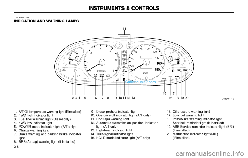
1. A/T Oil temperature warning light (If installed)
2. 4WD high indicator light
3. Fuel filter warning light (Diesel only)
4. 4WD low indicator light
5. POWER mode indicator light (A/T only)
6. Charge warning light
7. Brake warning and parking brake indicator
light
8. SRS (Airbag) warning light (If installed) 9. Diesel preheat indicator light
10. Overdrive off indicator light (A/T only)
11. Door-ajar warning light
12. Automatic transmission position indicator
light (A/T only)
13. High-beam indicator light
14. Turn-signal indicator light
15. HOLD mode indicator light (A/T only) 16. Oil pressure warning light
17. Low fuel warning light
18. Immobilizer warning indicator light/
Seat belt reminder light (If installed)
19. ABS Service reminder indicator light (SRI) (If installed)
20. Malfunction indicator light (MIL) (If installed)
2
C130A01P-3
14
13 678 1 618 19 20
17
12
111091 345
15
Page 48 of 173
2-9
INSTRUMENTS & CONTROLS
INSTRUMENTS & CONTROLS INSTRUMENTS & CONTROLS
INSTRUMENTS & CONTROLS
INSTRUMENTS & CONTROLS
C130B01P-GAT DOOR-AJAR WARNING
DOOR-AJAR WARNING DOOR-AJAR WARNING
DOOR-AJAR WARNING
DOOR-AJAR WARNING
LAMP-RED
LAMP-RED LAMP-RED
LAMP-RED
LAMP-RED
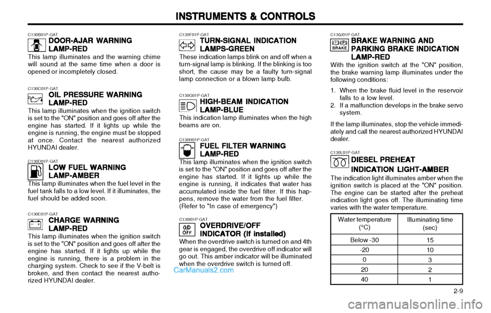
This lamp illuminates and the warning chime
will sound at the same time when a door is opened or incompletely closed.
C130F01P-GAT TURN-SIGNAL INDICATION
TURN-SIGNAL INDICATION TURN-SIGNAL INDICATION
TURN-SIGNAL INDICATION
TURN-SIGNAL INDICATION
LAMPS-GREEN
LAMPS-GREEN LAMPS-GREEN
LAMPS-GREEN
LAMPS-GREEN
These indication lamps blink on and off when a
turn-signal lamp is blinking. If the blinking is too short, the cause may be a faulty turn-signallamp connection or a blown lamp bulb.
C130G01P-GAT HIGH-BEAM INDICATION
HIGH-BEAM INDICATION HIGH-BEAM INDICATION
HIGH-BEAM INDICATION
HIGH-BEAM INDICATION
LAMP-BLUE
LAMP-BLUE LAMP-BLUE
LAMP-BLUE
LAMP-BLUE
This indication lamp illuminates when the high
beams are on.
C130H01P-GAT FUEL FILTER WARNING
FUEL FILTER WARNING FUEL FILTER WARNING
FUEL FILTER WARNING
FUEL FILTER WARNING
LAMP-RED
LAMP-RED LAMP-RED
LAMP-RED
LAMP-RED
This lamp illuminates when the ignition switch
is set to the "ON" position and goes off after the engine has started. If it lights up while theengine is running, it indicates that water hasaccumulated inside the fuel filter. If this hap-pens, remove the water from the fuel filter.
(Refer to "In case of emergency")
C130I01P-GAT OVERDRIVE/OFF
OVERDRIVE/OFF OVERDRIVE/OFF
OVERDRIVE/OFF
OVERDRIVE/OFF
INDICATOR (If installed)
INDICATOR (If installed) INDICATOR (If installed)
INDICATOR (If installed)
INDICATOR (If installed)
When the overdrive switch is turned on and 4th
gear is engaged, the overdrive off indicator will go out. This amber indicator will be illuminatedwhen the overdrive switch is turned off.
C130J01P-GAT BRAKE WARNING AND
BRAKE WARNING AND BRAKE WARNING AND
BRAKE WARNING AND
BRAKE WARNING AND
PARKING BRAKE INDICATION
PARKING BRAKE INDICATION PARKING BRAKE INDICATION
PARKING BRAKE INDICATION
PARKING BRAKE INDICATION
LAMP-RED
LAMP-RED LAMP-RED
LAMP-RED
LAMP-RED
With the ignition switch at the "ON" position,
the brake warning lamp illuminates under the following conditions:
1. When the brake fluid level in the reservoir falls to a low level.
2. If a malfunction develops in the brake servo system.
If the lamp illuminates, stop the vehicle immedi-
ately and call the nearest authorized HYUNDAI dealer.
C130C01P-GAT
OIL PRESSURE WARNING
OIL PRESSURE WARNING OIL PRESSURE WARNING
OIL PRESSURE WARNING
OIL PRESSURE WARNING
LAMP-RED
LAMP-RED LAMP-RED
LAMP-RED
LAMP-RED
This lamp illuminates when the ignition switch
is set to the "ON" position and goes off after theengine has started. If it lights up while theengine is running, the engine must be stoppedat once. Contact the nearest authorizedHYUNDAI dealer.
C130D01P-GAT LOW FUEL WARNING
LOW FUEL WARNING LOW FUEL WARNING
LOW FUEL WARNING
LOW FUEL WARNING
LAMP-AMBER
LAMP-AMBER LAMP-AMBER
LAMP-AMBER
LAMP-AMBER
This lamp illuminates when the fuel level in the
fuel tank falls to a low level. If it illuminates, the fuel should be added soon.
C130E01P-GAT CHARGE WARNING
CHARGE WARNING CHARGE WARNING
CHARGE WARNING
CHARGE WARNING
LAMP-RED
LAMP-RED LAMP-RED
LAMP-RED
LAMP-RED
This lamp illuminates when the ignition switch
is set to the "ON" position and goes off after the engine has started. If it lights up while theengine is running, there is a problem in thecharging system. Check to see if the V-belt isbroken, and then contact the nearest autho-rized HYUNDAI dealer.
C130L01P-GAT
DIESEL PREHEAT
DIESEL PREHEAT DIESEL PREHEAT
DIESEL PREHEAT
DIESEL PREHEAT
INDICATION LIGHT-AMBER
INDICATION LIGHT-AMBER INDICATION LIGHT-AMBER
INDICATION LIGHT-AMBER
INDICATION LIGHT-AMBER
The indication light illuminates amber when the
ignition switch is placed at the "ON" position. The engine can be started after the preheatindication light goes off. The illuminating timevaries with the water temperature.
Water temperature
(°C)
Below -30 -20
0
20 40 Illuminating time
(sec)
151032 1
Page 50 of 173

2-11
INSTRUMENTS & CONTROLS
INSTRUMENTS & CONTROLS INSTRUMENTS & CONTROLS
INSTRUMENTS & CONTROLS
INSTRUMENTS & CONTROLS
C150A01P-GATTURN SIGNAL SWITCH
TURN SIGNAL SWITCH TURN SIGNAL SWITCH
TURN SIGNAL SWITCH
TURN SIGNAL SWITCH
C140A01P-GAT
MULTI-FUNCTION LIGHT SWITCH
MULTI-FUNCTION LIGHT SWITCH MULTI-FUNCTION LIGHT SWITCH
MULTI-FUNCTION LIGHT SWITCH
MULTI-FUNCTION LIGHT SWITCH
Pulling down on the lever causes the turn
signals on the left side of the car to blink. Pushing upward on the lever causes the turnsignals on the right side of the car to blink. Asthe turn is completed, the lever will automati-cally return to the center position and turn offthe turn signals at the same time. If either turnsignal indicator light blinks more rapidly thanusual, goes on but does not blink, or does notgo on at all, there is a malfunction in thesystem. Check for a burned-out fuse or bulb orsee your Hyundai dealer.
Rotate the switch to turn on the lights.
1. Lights off
2. Position, tail, licence-plate, and instrument panel lamps on
3. Headlights on To operate the headlights, turn the barrel onthe end of the multifunction switch.
Parking light auto cut (If installed)
Parking light auto cut (If installed) Parking light auto cut (If installed)
Parking light auto cut (If installed)
Parking light auto cut (If installed)
If you do not turn the parking lights "OFF" after
driving, the parking light will automatically shut"OFF" when the driver's door is opened.
To turn them "ON" again you must simply turn
the ignition key to the "ON" position. C160A01P-GAT
HIGH-BEAM SWITCH
HIGH-BEAM SWITCH HIGH-BEAM SWITCH
HIGH-BEAM SWITCH
HIGH-BEAM SWITCH
To turn on the headlight high beams, push the
lever forward (away from you). The High BeamIndicator Light will come on at the same time.For low beams, pull the lever back toward you.
C170A01P-GATPASSING SWITCH
PASSING SWITCH PASSING SWITCH
PASSING SWITCH
PASSING SWITCH
HSR2114HSR2113HSR2112
1 2
3
HSR2115
Page 55 of 173
INSTRUMENTS & CONTROLS
INSTRUMENTS & CONTROLS INSTRUMENTS & CONTROLS
INSTRUMENTS & CONTROLS
INSTRUMENTS & CONTROLS
2-16 B380A01A-AAT
REAR WINDOW DEFROSTER SWITCH
REAR WINDOW DEFROSTER SWITCH REAR WINDOW DEFROSTER SWITCH
REAR WINDOW DEFROSTER SWITCH
REAR WINDOW DEFROSTER SWITCH
(If installed)
(If installed) (If installed)
(If installed)
(If installed)
B380A01A-AAG
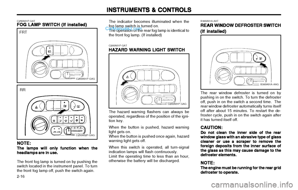
The rear window defroster is turned on by
pushing in on the switch. To turn the defrosteroff, push in on the switch a second time. The
rear window defroster automatically turns itselfoff after about 15 minutes. To restart the de-froster cycle, push in on the switch again after
it has turned itself off. CAUTION:
CAUTION: CAUTION:
CAUTION:
CAUTION:
Do not clean the inner side of the rear
Do not clean the inner side of the rear Do not clean the inner side of the rear
Do not clean the inner side of the rear
Do not clean the inner side of the rear
window glass with an
window glass with an window glass with an
window glass with an
window glass with an abrasive type of glass
abrasive type of glass abrasive type of glass
abrasive type of glass
abrasive type of glass
cleaner or use a scraper to remove the
cleaner or use a scraper to remove the cleaner or use a scraper to remove the
cleaner or use a scraper to remove the
cleaner or use a scraper to remove the
foreign deposits
foreign deposits foreign deposits
foreign deposits
foreign deposits from the inner surface of
from the inner surface of from the inner surface of
from the inner surface of
from the inner surface of
the glass as this may cause damage to the
the glass as this may cause damage to the the glass as this may cause damage to the
the glass as this may cause damage to the
the glass as this may cause damage to the
defroster
defroster defroster
defroster
defroster
elements.
elements. elements.
elements.
elements.
NOTE:
NOTE: NOTE:
NOTE:
NOTE:
The engine must be running for the rear grid
The engine must be running for the rear grid The engine must be running for the rear grid
The engine must be running for the rear grid
The engine must be running for the rear grid
defroster to operate.
defroster to operate. defroster to operate.
defroster to operate.
defroster to operate.
C260A01P-GAT
HAZARD WARNING LIGHT SWITCH
HAZARD WARNING LIGHT SWITCH HAZARD WARNING LIGHT SWITCH
HAZARD WARNING LIGHT SWITCH
HAZARD WARNING LIGHT SWITCHThe indicator becomes illuminated when thefog lamp switch is turned on. The operation of the rear fog lamp is identical to the front fog lamp. (If installed)
C260A01P-GAG
The hazard warning flashers can always be operated, regardless of the position of the igni-tion key. When the button is pushed, hazard warning light gets on. When the button is pushed once again, hazard warning light gets off. When this switch is operated, all turn-signal indication lamps will flash continuously. Limit the operating time to less than an hour, otherwise the battery will be discharged.
C250A01P-GAT
FOG LAMP SWITCH
FOG LAMP SWITCH FOG LAMP SWITCH
FOG LAMP SWITCH
FOG LAMP SWITCH
(If installed)
(If installed) (If installed)
(If installed)
(If installed)
C250A01P-GAG
FRT
C250A02P-GAG
RR
NOTE:
NOTE: NOTE:
NOTE:
NOTE:
The lamps will only function when the
The lamps will only function when the The lamps will only function when the
The lamps will only function when the
The lamps will only function when the headlamps are in use.
headlamps are in use. headlamps are in use.
headlamps are in use.
headlamps are in use.
The front fog lamp is turned on by pushing the
switch located in the instrument panel. To turn the front fog lamp off, push the switch again.
Page 88 of 173

2-49
INSTRUMENTS & CONTROLS
INSTRUMENTS & CONTROLS INSTRUMENTS & CONTROLS
INSTRUMENTS & CONTROLS
INSTRUMENTS & CONTROLS
H290B01P-GAT 1.1.
1.1.
1. POWER ON-OFF Control Knob
POWER ON-OFF Control Knob POWER ON-OFF Control Knob
POWER ON-OFF Control Knob
POWER ON-OFF Control Knob
The radio unit may be operated when the igni-
tion key is in the "ACC" or "ON" position. Press the button to switch the power on. The displayshows the radio frequency in the radio mode orthe tape direction indicator in the tape mode, orCD track either the CD mode or CD AUTOCHANGER mode. To switch the power off,press the button again.
VOLUME Control
VOLUME Control VOLUME Control
VOLUME Control
VOLUME Control
Rotate the knob clockwise to increase the vol-
ume and turn the knob counterclockwise toreduce the volume.
2.2.
2.2.
2.
BASS/BALANCE Control Knob
BASS/BALANCE Control Knob BASS/BALANCE Control Knob
BASS/BALANCE Control Knob
BASS/BALANCE Control Knob
BASS Control Knob
BASS Control Knob BASS Control Knob
BASS Control Knob
BASS Control Knob
Press to pop the knob out. To increase the
bass, rotate the knob clockwise, while to de-crease the bass, rotate the knob counterclock-wise.
BALANCE Control knob
BALANCE Control knob BALANCE Control knob
BALANCE Control knob
BALANCE Control knob
Further pull the popped-up knob. Rotate the
knob clockwise to emphasize right speakersound. (Left speaker sound will be attenuated)When the control knob is turned counterclock-wise, left speaker sound will be emphasized(Right speaker sound will be attenuated). 3.3.
3.3.
3. TREBLE/FAD Knob
TREBLE/FAD Knob TREBLE/FAD Knob
TREBLE/FAD Knob
TREBLE/FAD Knob
TREBLE Control Knob
TREBLE Control Knob TREBLE Control Knob
TREBLE Control Knob
TREBLE Control Knob
Press to pop the knob out and turn to the left or
right for the desired treble tone.
FAD (Fader Control) Knob (Minibus
FAD (Fader Control) Knob (Minibus FAD (Fader Control) Knob (Minibus
FAD (Fader Control) Knob (Minibus
FAD (Fader Control) Knob (Minibus
only)
only) only)
only)
only)
Further pull the popped-up knob. Turn the con-
trol knob counterclockwise to emphasize frontspeaker sound. (Rear speaker sound will beattenuated) When the control knob is turnedclockwise, rear speaker sound will be empha-sized. (Front speaker sound will be attenuated)
4.4.
4.4.
4.
TUNE (Manual) Select Button
TUNE (Manual) Select Button TUNE (Manual) Select Button
TUNE (Manual) Select Button
TUNE (Manual) Select Button
Press the ( ) side or ( ) side to increase or to
decrease the frequency. With the button helddown for 0.5 sec. or more, the stop signal(broadcasting radio wave) is ignored and chan-nel selection continues.
SEEK Operation (Automatic Channel
SEEK Operation (Automatic Channel SEEK Operation (Automatic Channel
SEEK Operation (Automatic Channel
SEEK Operation (Automatic Channel
Selection)
Selection) Selection)
Selection)
Selection)
Press the TUNE select button for 1 sec or
more, and releasing will automatically tune thenext available station with beep sound. When the ( ) side is pressed longer than 1
second and releasing will automatically tunethe next higher frequency and when the ( )side is pressed longer than 1 second and re-leasing will automatically tune the next lowerfrequency. 5.5.
5.5.
5. PRESET STATION Select Buttons
PRESET STATION Select Buttons PRESET STATION Select Buttons
PRESET STATION Select Buttons
PRESET STATION Select Buttons
Six (6) stations for AM, FM and FM2 respec-
tively can be preset in the electronic memorycircuit.
HOW TO PRESET STATIONS
HOW TO PRESET STATIONS HOW TO PRESET STATIONS
HOW TO PRESET STATIONS
HOW TO PRESET STATIONS
Six AM and twelve FM stations may be pro-
grammed into the memory of the radio. Then,by simply pressing the band select button and/or one of the six station select buttons, you mayrecall any of these stations instantly. To pro-gram the stations, follow these steps:
o Press band selector to set the band for AM, FM and FM2.
o Select the desired station to be stored by seek or manual tuning.
o Determine the preset station select button you wish to use to access that station.
o Press the station select button for more than two seconds. A select button indicator will show in the display indicating which selectbutton you have depressed. The frequencydisplay will flash after it has been stored intothe memory with beep sound. You shouldthen release the button, and proceed toprogram the next desired station. A total of18 stations can be programmed by selectingone AM and two FM station per button.
o When completed, any preset station may be recalled by selecting AM, FM or FM2 bandand the appropriate station button.
Page 97 of 173

INSTRUMENTS & CONTROLS
INSTRUMENTS & CONTROLS INSTRUMENTS & CONTROLS
INSTRUMENTS & CONTROLS
INSTRUMENTS & CONTROLS
2-58
B870A01A-GAT ANTENNA
ANTENNA ANTENNA
ANTENNA
ANTENNA
Fixed Rod Antenna (If installed)
Fixed Rod Antenna (If installed) Fixed Rod Antenna (If installed)
Fixed Rod Antenna (If installed)
Fixed Rod Antenna (If installed)
Your car uses a fixed rod antenna to receive
both AM and FM broadcast signals.
This antenna is a removable type. To remove
the antenna, turn the antenna counterclock- wise. To install the antenna, turn the antennaclockwise.
CAUTION:
CAUTION: CAUTION:
CAUTION:
CAUTION:
Be sure to remove the antenna before wash-
Be sure to remove the antenna before wash- Be sure to remove the antenna before wash-
Be sure to remove the antenna before wash-
Be sure to remove the antenna before wash- ing the car in an automatic car wash or the
ing the car in an automatic car wash or the ing the car in an automatic car wash or the
ing the car in an automatic car wash or the
ing the car in an automatic car wash or the
antenna may be damaged.
antenna may be damaged. antenna may be damaged.
antenna may be damaged.
antenna may be damaged. B870B01Y-AAT
Power Antenna (If installed)
Power Antenna (If installed) Power Antenna (If installed)
Power Antenna (If installed)
Power Antenna (If installed)
B870C01A-GAT
Manual Antenna
Manual Antenna Manual Antenna
Manual Antenna
Manual Antenna
B870C01P
Your car uses a manual stainless steel antenna
to receive both AM and FM broadcast signals. Pull up the antenna using your fingers, asshown in the drawing.
NOTE:
NOTE: NOTE:
NOTE:
NOTE:
Before entering an automatic car wash or a
Before entering an automatic car wash or a Before entering an automatic car wash or a
Before entering an automatic car wash or a
Before entering an automatic car wash or a place with a low height clearance, be sure
place with a low height clearance, be sure place with a low height clearance, be sure
place with a low height clearance, be sure
place with a low height clearance, be sure
that the antenna is fully retracted.
that the antenna is fully retracted. that the antenna is fully retracted.
that the antenna is fully retracted.
that the antenna is fully retracted.B870B01P
The antenna will automatically be extended when the radio power switch is turned on whilethe ignition key is in either the "ON" or "ACC"position. The antenna will automatically be re-tracted and stored when either the radio powerswitch is turned off or the ignition key is set tothe "LOCK" position.
NOTE:
NOTE: NOTE:
NOTE:
NOTE:
oo
oo
o Before turning on the radio, make sure
Before turning on the radio, make sure Before turning on the radio, make sure
Before turning on the radio, make sure
Before turning on the radio, make sure
that no one is near the antenna.
that no one is near the antenna. that no one is near the antenna.
that no one is near the antenna.
that no one is near the antenna.
oo
oo
o Before entering an automatic car wash
Before entering an automatic car wash Before entering an automatic car wash
Before entering an automatic car wash
Before entering an automatic car wash
or a place with a low height clearance, be
or a place with a low height clearance, be or a place with a low height clearance, be
or a place with a low height clearance, be
or a place with a low height clearance, be
sure that the antenna is retracted and
sure that the antenna is retracted and sure that the antenna is retracted and
sure that the antenna is retracted and
sure that the antenna is retracted and
stored.
stored. stored.
stored.
stored.
oo
oo
o
If the antenna is dirty, be sure to clean it
If the antenna is dirty, be sure to clean it If the antenna is dirty, be sure to clean it
If the antenna is dirty, be sure to clean it
If the antenna is dirty, be sure to clean it
in order to avoid an operation malfunc-
in order to avoid an operation malfunc- in order to avoid an operation malfunc-
in order to avoid an operation malfunc-
in order to avoid an operation malfunc-
tion.
tion. tion.
tion.
tion.
B870A01F
Page 123 of 173

IN CASE OF EMERGENCY
IN CASE OF EMERGENCY IN CASE OF EMERGENCY
IN CASE OF EMERGENCY
IN CASE OF EMERGENCY
4-8 The regulations concerning towing may differ from country to country. It is recommended thatyou may obey the regulations in your area. Ifyour vehicle is to be towed, pay careful atten-tion to the following points.
C190A01A-GATTRAILER OR VEHICLE TOWING
TRAILER OR VEHICLE TOWING TRAILER OR VEHICLE TOWING
TRAILER OR VEHICLE TOWING
TRAILER OR VEHICLE TOWING
If you are considering towing with your car, youshould first check with your Province Depart-ment of Motor Vehicles to determine their legal requirements.Since laws vary from province to province, the requirements for towing trailers, cars, othertypes of vehicles, or apparatus may differ. Askyour Hyundai dealer for further details beforetowing.
GX40250A
Rear (Minbus, Van)Towing hook
(1) Move the gearshift lever to neutral.
(2) Be sure the towing speed is within the legal limit.
(3) On vehicles with steering lock system, turn the ignition switch to "ACC" to unlock the steering wheel. If you will be using the turnsignals while being towed, turn the ignitionswitch to "ON" position.
(4) To prevent the exhaust gas from entering the towing vehicle, set the air selection leveron the heater control to the recirculationposition.
(5) Turn on the hazard warning lamps.
(6) During towing, make sure that close contact is maintained between the drivers of both vehicles, and that the vehicles travel at low speed. Avoid abrupt starting or stoppingwhich might subject the vehicles to shock.
(7) If the transmission is malfunctioning or dam- aged, tow the vehicle with the rear wheelsraised off the ground.
(8) If the vehicle is equipped with a brake boost- er system, the brake boosting power will belost and greater force will be required todepress the brake pedal.
(9) If the vehicle is equipped with a power steering system, greater force will be re-quired to operate the steering wheel.
NOTE:
NOTE: NOTE:
NOTE:
NOTE:
Your vehicle should only be used to tow
Your vehicle should only be used to tow Your vehicle should only be used to tow
Your vehicle should only be used to tow
Your vehicle should only be used to tow another vehicle if the weight of the other
another vehicle if the weight of the other another vehicle if the weight of the other
another vehicle if the weight of the other
another vehicle if the weight of the other
vehicle is less than that of your vehicle.
vehicle is less than that of your vehicle. vehicle is less than that of your vehicle.
vehicle is less than that of your vehicle.
vehicle is less than that of your vehicle.
E070A01P-GAT
TOWING
TOWING TOWING
TOWING
TOWING
GX40240A
Front (Minbus, Van)
Towing hook
Tow at the illustrated point. Using any part other than the designated towing
hooks could result in damage to vehicle body.
GY40240B
Front (Truck)
13. After the spare tire is once again replaced
by the original tire, adjust the inflation pres- sure to the correct specification.
Page 126 of 173

IN CASE OF EMERGENCY
IN CASE OF EMERGENCY IN CASE OF EMERGENCY
IN CASE OF EMERGENCY
IN CASE OF EMERGENCY
4-11
9. If the trailer has electric brakes, start your
vehicle and trailer moving, and then apply the trailer brake controller by hand to besure the brakes are working. This lets you
check your electrical connection at the sametime.
10. During your trip, check occasionally to be sure that the load is secure, and that thelights and any trailer brakes are still working.
11. Avoid jerky starts, sudden acceleration or sudden stops.
12. Avoid sharp turns and rapid lane changes.
13. Avoid holding the brake pedal down too long or too frequently. This could cause the brakes to overheat, resulting in reduced brakingefficiency.
14. When going down a hill, shift into a lower gear and use the engine braking effect.When ascending a long grade, downshift the
transmission to a lower gear and reducespeed to reduce chances of engine over-
loading and/or overheating.
15. If you have to stop while going uphill, do not hold the vehicle in place by pressing on theaccelerator. This can cause the automatictransmission to overheat. Use the parkingbrake or footbrake.
NOTE:
NOTE: NOTE:
NOTE:
NOTE:
When towing, check transmission fluid more
When towing, check transmission fluid more When towing, check transmission fluid more
When towing, check transmission fluid more
When towing, check transmission fluid more frequently.
frequently. frequently.
frequently.
frequently. CAUTION:
CAUTION: CAUTION:
CAUTION:
CAUTION:
If overheating should occur when towing,
If overheating should occur when towing, If overheating should occur when towing,
If overheating should occur when towing,
If overheating should occur when towing,(temperature gauge
(temperature gauge (temperature gauge
(temperature gauge
(temperature gauge
reads near red zone),
reads near red zone), reads near red zone),
reads near red zone),
reads near red zone),
taking the following action may reduce or
taking the following action may reduce or taking the following action may reduce or
taking the following action may reduce or
taking the following action may reduce or
eliminate
eliminate eliminate
eliminate
eliminate
the problem.
the problem. the problem.
the problem.
the problem.
1.1.
1.1.
1. Turn off the air conditioner.
Turn off the air conditioner. Turn off the air conditioner.
Turn off the air conditioner.
Turn off the air conditioner.
2.2.
2.2.
2. Reduce highway speed.
Reduce highway speed. Reduce highway speed.
Reduce highway speed.
Reduce highway speed.
3.3.
3.3.
3. Select a lower gear when going uphill.
Select a lower gear when going uphill. Select a lower gear when going uphill.
Select a lower gear when going uphill.
Select a lower gear when going uphill.
4.4.
4.4.
4. While in stop and go traffic, place the
While in stop and go traffic, place the While in stop and go traffic, place the
While in stop and go traffic, place the
While in stop and go traffic, place the
gear selection in park
gear selection in park gear selection in park
gear selection in park
gear selection in park or neutral and idle
or neutral and idle or neutral and idle
or neutral and idle
or neutral and idle
the engine at a higher speed.
the engine at a higher speed. the engine at a higher speed.
the engine at a higher speed.
the engine at a higher speed.
C190F01A-GAT
Trailer or Vehicle Towing Tips
Trailer or Vehicle Towing Tips Trailer or Vehicle Towing Tips
Trailer or Vehicle Towing Tips
Trailer or Vehicle Towing Tips
1. Before towing, check hitch and safety chain
connections as well as proper operation of the trailer running lights, brake lights, andturn signals.
2. Always drive your vehicle at a moderate speed (Less than 100 km/h).
3. Trailer towing requires more fuel than nor- mal conditions.
4. To maintain engine braking efficiency and electrical charging performance, do not usefifth gear (manual transmission) or overdrive(automatic transmission).
5. Always secure items in the trailer to prevent load shift while driving.
6. Check the condition and air pressure of all tires on the trailer and your car. Low tirepressure can seriously affect the handling.
Also check the spare tire.
7. The vehicle/trailer combination is more af- fected by crosswind and buffeting. Whenbeing passed by a large vehicle, keep aconstant speed and steer straight ahead. Ifthere is too much wind buffeting slow downto get out of the other vehicle’s air turbu-lence.
8. When parking your car and trailer, especial- ly on a hill, be sure to follow all the normalprecautions. Turn your front wheel into the
curb, set the parking brake firmly, and putthe transmission in 1st or Reverse (manual)or Park (automatic). In addition, place wheel
chocks at each of the trailer’s tires. D030A01A-AAT
IF THE ENGINE OVERHEATS
IF THE ENGINE OVERHEATS IF THE ENGINE OVERHEATS
IF THE ENGINE OVERHEATS
IF THE ENGINE OVERHEATS
GT40260A
If your temperature gauge indicates overheat-
ing, you experience a loss of power, or hear loud pinging or knocking and the engine isprobably too hot. If this happens to you, youshould: