reset HYUNDAI IONIQ 5 2023 Owner's Manual
[x] Cancel search | Manufacturer: HYUNDAI, Model Year: 2023, Model line: IONIQ 5, Model: HYUNDAI IONIQ 5 2023Pages: 680, PDF Size: 48.22 MB
Page 456 of 680
Driver Assistance System
7-54
Information
When the accelerator pedal is not
depressed beyond the pressure point, vehicle speed will maintain within the speed limit.
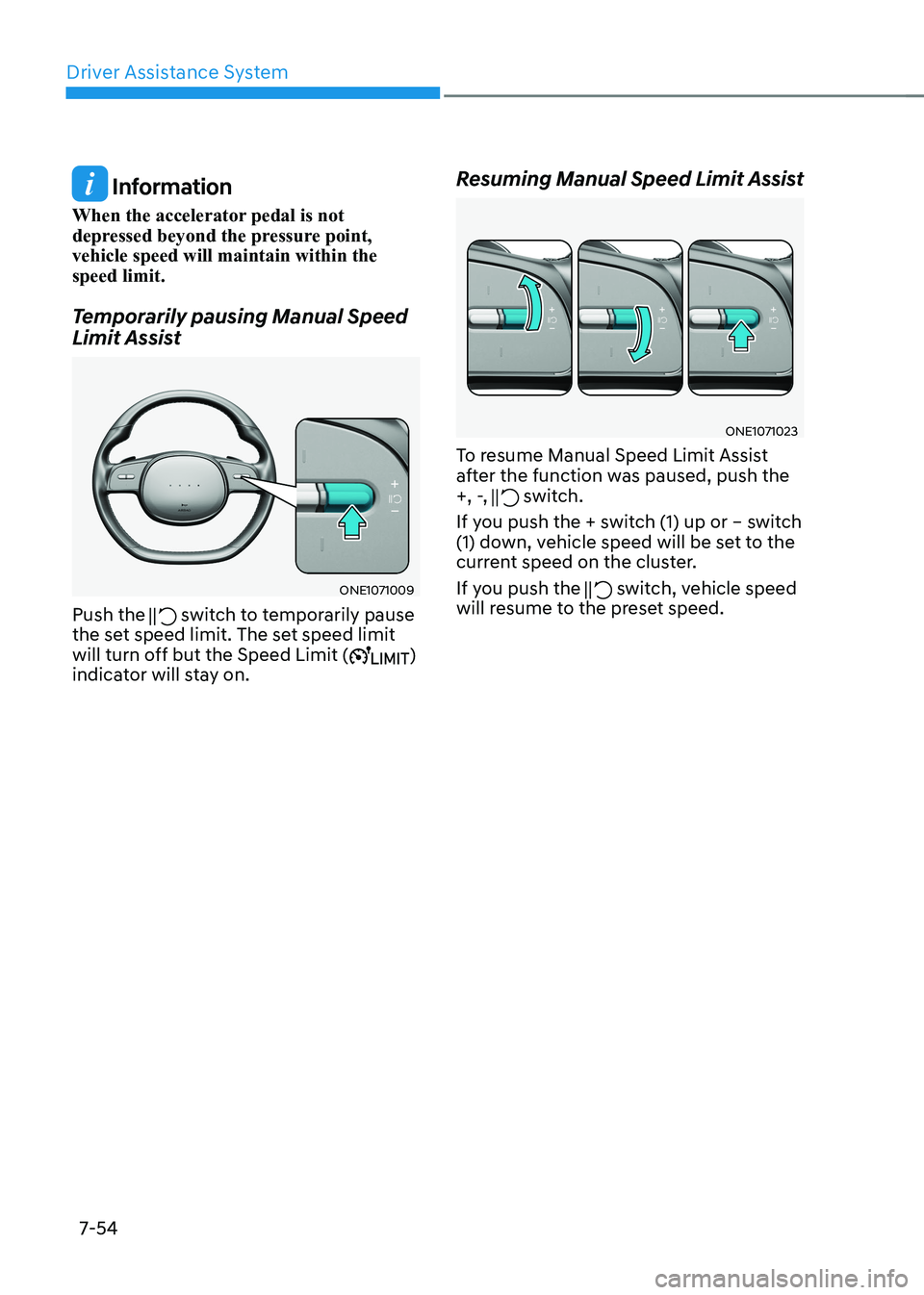
Temporarily pausing Manual Speed
Limit Assist
ONE1071009
Push the
switch to temporarily pause
the set speed limit. The set speed limit
will turn off but the Speed Limit (
)
indicator will stay on. Resuming Manual Speed Limit Assist
ONE1071023
To resume Manual Speed Limit Assist
after the function was paused, push the
+, -,
switch.
If you push the + switch (1) up or – switch
(1) down, vehicle speed will be set to the
current speed on the cluster.
If you push the
switch, vehicle speed
will resume to the preset speed.
Page 466 of 680
Driver Assistance System
7-64
•
The driver’s attention level is displayed
on the scale of 1 to 5. The lower the
level is, the more inattentive the driver is.
• The level decreases when the driver
does not take a break for a certain
period of time.
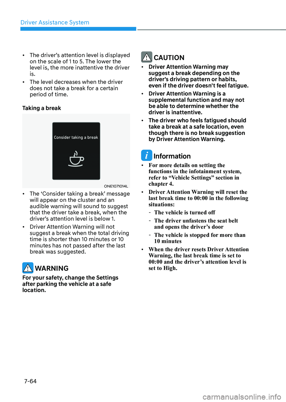
Taking a break
ONE1071014L
• The ‘Consider taking a break’ message
will appear on the cluster and an
audible warning will sound to suggest
that the driver take a break, when the
driver’s attention level is below 1.
• Driver Attention Warning will not
suggest a break when the total driving
time is shorter than 10 minutes or 10
minutes has not passed after the last
break was suggested.
WARNING
For your safety, change the Settings
after parking the vehicle at a safe
location.
CAUTION
• Driver Attention Warning may
suggest a break depending on the
driver’s driving pattern or habits,
even if the driver doesn’t feel fatigue.
• Driver Attention Warning is a
supplemental function and may not
be able to determine whether the
driver is inattentive.
• The driver who feels fatigued should
take a break at a safe location, even
though there is no break suggestion
by Driver Attention Warning.
Information
• For more details on setting the functions in the infotainment system,
refer to “Vehicle Settings” section in
chapter 4.
• Driver Attention Warning will reset the
last break time to 00:00 in the following situations:
- The vehicle is turned off
- The driver unfastens the seat belt
and opens the driver’s door
- The vehicle is stopped for more than 10 minutes
• When the driver resets Driver Attention
Warning, the last break time is set to
00:00 and the driver’s attention level is set to High.
Page 475 of 680
07
7-7 3
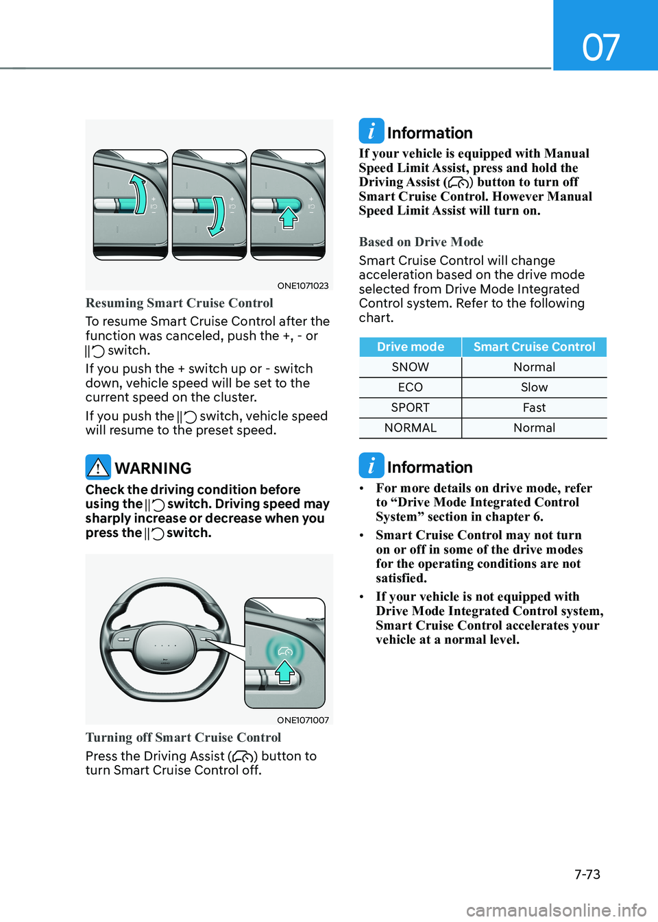
ONE1071023
Resuming Smart Cruise Control
To resume Smart Cruise Control after the
function was canceled, push the +, - or
switch.
If you push the + switch up or - switch
down, vehicle speed will be set to the
current speed on the cluster.
If you push the
switch, vehicle speed
will resume to the preset speed.
WARNING
Check the driving condition before using the
switch. Driving speed may
sharply increase or decrease when you
press the
switch.
ONE1071007
Turning off Smart Cruise Control
Press the Driving Assist () button to
turn Smart Cruise Control off.
Information
If your vehicle is equipped with Manual
Speed Limit Assist, press and hold the Driving Assist (
) button to turn off
Smart Cruise Control. However Manual
Speed Limit Assist will turn on.
Based on Drive Mode
Smart Cruise Control will change
acceleration based on the drive mode
selected from Drive Mode Integrated
Control system. Refer to the following chart.
Drive mode Smart Cruise Control
SNOW Normal
ECO Slow
SPORT Fast
NORMAL Normal
Information
• For more details on drive mode, refer
to “Drive Mode Integrated Control
System” section in chapter 6.
• Smart Cruise Control may not turn
on or off in some of the drive modes
for the operating conditions are not satisfied.
• If your vehicle is not equipped with
Drive Mode Integrated Control system,
Smart Cruise Control accelerates your vehicle at a normal level.
Page 495 of 680
07
7-93
•
The driver goes off course the route
set in the navigation
• The route to the destination is
changed or canceled by resetting the
navigation
• The vehicle enters a service station or
rest area
• Android Auto or Car Play is operating
• The navigation cannot detect the
current vehicle position (for example,
elevated roads including overpass
adjacent to general roads or nearby
roads exist in a parallel way)
• The navigation is being updated while driving
• The navigation is being restarted while driving
• The speed limit of some sections
changes according to the road
situations
• Driving on a road under construction
• Driving on a road that is controlled
• There is bad weather, such as heavy
rain, heavy snow, etc.
• Driving on a road that is sharply
curved
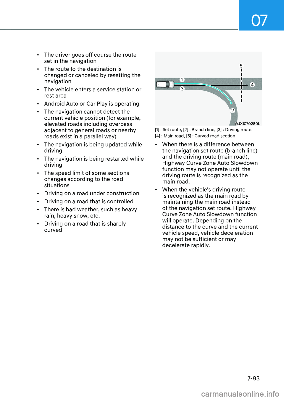
OJX1070280L
[1] : Set route, [2] : Branch line, [3] : Driving route,
[4] : Main road, [5] : Curved road section • When there is a difference between
the navigation set route (branch line)
and the driving route (main road),
Highway Curve Zone Auto Slowdown
function may not operate until the
driving route is recognized as the
main road.
• When the vehicle's driving route
is recognized as the main road by
maintaining the main road instead
of the navigation set route, Highway
Curve Zone Auto Slowdown function
will operate. Depending on the
distance to the curve and the current
vehicle speed, vehicle deceleration
may not be sufficient or may
decelerate rapidly.
Page 514 of 680
Driver Assistance System
7-112
•
If the vehicle is driven at high speed
above a certain speed at a curve,
your vehicle may drive to one side or
may depart from the driving lane.
• When you are towing a trailer or
another vehicle, turn off Highway
Driving Assist for safety reasons.
• The hands–off warning message
may appear early or late depending
on how the steering wheel is held or
road conditions. Always have your
hands on the steering wheel while driving.
• For your safety, please read the
owner's manual before using the
Highway Driving Assist.
• Highway Driving Assist will not
operate when the vehicle is started,
or when the detecting sensors or
navigation is being initialized.
Limitations of Highway Driving
Assist
Highway Driving Assist and Highway
Lane Change function may not operate
properly, or may not operate under the
following circumstances: • The map information and the
actual road is different because the
navigation is not updated
• The map information and the actual
road is different because of real-time
GPS data or map information error
• The infotainment system is overloaded
by simultaneously performing
functions such as route search, video
playback, voice recognition, etc. •
GPS signals are blocked in areas such as a tunnel
• The driver goes off course or the
route to the destination is changed or
canceled by resetting the navigation
• The vehicle enters a service station or
rest area
• Android Auto or Car Play is operating
• The navigation cannot detect the
current vehicle position (for example,
elevated roads including overpass
adjacent to general roads or nearby
roads exist in a parallel way)
• White single dotted lane line or road
edge cannot be detected
• The road is temporarily controlled due
to construction, etc.
• There is no structure, such as a
medium strip, guardrails, etc., on the
road
• There is a changeable lane in the
direction of lane change
Information
For more details on the limitations of
the front view camera, front radar, front
corner radar and rear corner radar, refer
to “Forward Collision-Avoidance Assist
(FCA)” section in this chapter.
Page 602 of 680
9
9. Maintenance
Motor Compartment ........................................................................................ 9-3
Maintenance Services ...................................................................................... 9-4
Owner’s Responsibility ............................................................................................... 9-4
Owner Maintenance Precautions ............................................................................... 9-4
Owner Maintenance ......................................................................................... 9-5
Owner Maintenance Schedule ................................................................................... 9-6
Scheduled Maintenance Services .................................................................... 9 -7
Normal Maintenance Schedule ................................................................................. 9-8
Normal Maintenance Schedule .................................................................................. 9-9
Maintenance Under Severe Usage Conditions ........................................................9-10
Explanation of Scheduled Maintenance Items ...............................................9-11
Coolant ............................................................................................................. 9-12
Brake Fluid ........................................................................................................ 9-13
Checking the Brake Fluid Level ................................................................................. 9-13
Reduction Gear Fluid ....................................................................................... 9-14
Washer Fluid ..................................................................................................... 9-14
Checking the Washer Fluid Level .............................................................................. 9-14
Cabin Air Filter .................................................................................................. 9-15
Filter Inspection.......................................................................................................... 9-15 Filter Replacement ..................................................................................................... 9-15
Wiper Blades .................................................................................................... 9-16
Blade Inspection ........................................................................................................ 9-16
Blade Replacement .................................................................................................... 9-16
Battery (12 volt) ................................................................................................ 9-19
For best battery service ............................................................................................ 9-20
Battery Capacity Label .............................................................................................. 9-20
Battery Recharging ................................................................................................... 9-20
Reset Items ................................................................................................................. 9-21
Page 622 of 680
09
9-21
WARNING
Always follow these instructions when
recharging your vehicle’s battery to
avoid the risk of SERIOUS INJURY or
DEATH from explosions or acid burns: • Before performing maintenance or
recharging the battery, turn off all
accessories and stop the vehicle.
• Keep all flames, sparks, or smoking
materials away from the battery.
• Always work outdoors or in an area
with plenty of ventilation.
• Wear eye protection when checking
the battery during charging.
• The battery must be removed from
the vehicle and placed in a well
ventilated area.
• Watch the battery during charging,
and stop or reduce the charging
rate if the battery cells begin boiling
violently.
• The negative battery cable must
be removed first and installed last
when the battery is disconnected.
Disconnect the battery charger in the
following order:
1. Turn off the battery charger main
switch.
2. Unhook the negative clamp from the negative battery terminal.
3. Unhook the positive clamp from the positive battery terminal.
• Use batteries for replacement from
an authorized HYUNDAI dealer. By jump starting
After a jump start from a good battery,
drive the vehicle for 20-30 minutes
before it is shutoff. The vehicle may
not restart if you shut it off before the
battery had a chance to adequately
recharge. See “Jump Starting” in chapter
8 for more information on jump starting
procedures.
Information
An inappropriately disposed battery can be harmful to the
environment and human health. Dispose of the battery according
to your local law(s) or regulation.
Reset Items
The following items may need to be reset
after the battery has been discharged or
the battery has been disconnected. •
Driving info/After recharging/
Accumulated info (items in Utility
view) (see chapter 4)
• Integrated memory system (see
chapter 5)
• Power window (see chapter 5)
• Vision roof (see chapter 5)
• Power liftgate (see chapter 5)
• Climate control system (see chapter 5)
• Clock (see Infotainment system manual)
• Infotainment system (see
Infotainment system manual)
Page 626 of 680
09
9-25
Wheel Alignment and Tire
Balance
The wheels on your vehicle were aligned
and balanced carefully at the factory to
give you the longest tire life and best
overall performance.
In most cases, you will not need to have
your wheels aligned again. However,
if you notice unusual tire wear or your
vehicle pulling one way or the other, the
alignment may need to be reset.
If you notice your vehicle vibrating when
driving on a smooth road, your wheels
may need to be rebalanced.
NOTICE
Incorrect wheel weights can damage
your vehicle’s aluminum wheels. Use
only approved wheel weights.
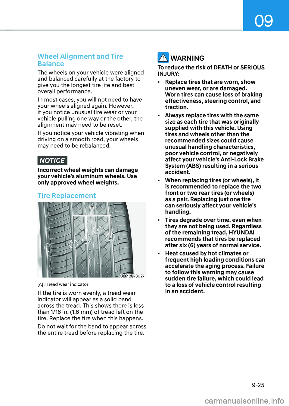
Tire Replacement
OLMB073027
A
[A] : Tread wear indicator
If the tire is worn evenly, a tread wear
indicator will appear as a solid band
across the tread. This shows there is less
than 1/16 in. (1.6 mm) of tread left on the
tire. Replace the tire when this happens.
Do not wait for the band to appear across
the entire tread before replacing the tire.
WARNING
To reduce the risk of DEATH or SERIOUS
INJURY: • Replace tires that are worn, show
uneven wear, or are damaged.
Worn tires can cause loss of braking
effectiveness, steering control, and
traction.
• Always replace tires with the same
size as each tire that was originally
supplied with this vehicle. Using
tires and wheels other than the
recommended sizes could cause
unusual handling characteristics,
poor vehicle control, or negatively
affect your vehicle’s Anti-Lock Brake
System (ABS) resulting in a serious
accident.
• When replacing tires (or wheels), it
is recommended to replace the two
front or two rear tires (or wheels)
as a pair. Replacing just one tire
can seriously affect your vehicle’s handling.
• Tires degrade over time, even when
they are not being used. Regardless
of the remaining tread, HYUNDAI
recommends that tires be replaced
after six (6) years of normal service.
• Heat caused by hot climates or
frequent high loading conditions can
accelerate the aging process. Failure
to follow this warning may cause
sudden tire failure, which could lead
to a loss of vehicle control resulting
in an accident.
Page 668 of 680
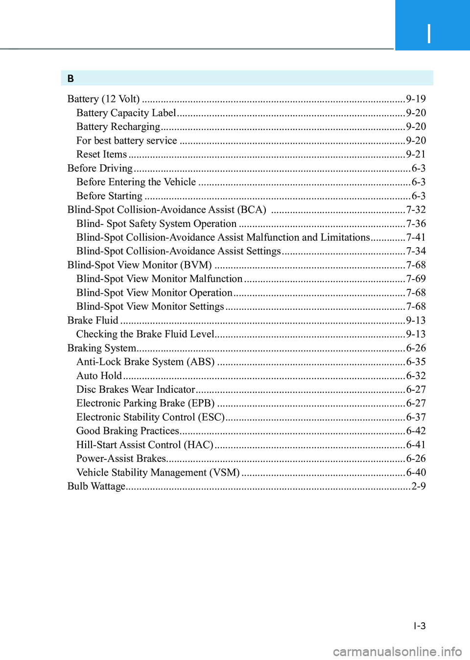
I
I-3
B
Battery (12 Volt) .................................................................................................. 9-19
Battery Capacity Label ..................................................................................... 9-20
Battery Recharging ........................................................................................... 9-20
For best battery service .................................................................................... 9-20
Reset Items ....................................................................................................... 9-21
Before Driving ....................................................................................................... 6-3
Before Entering the Vehicle ............................................................................... 6-3
Before Starting ................................................................................................... 6-3
Blind-Spot Collision-Avoidance Assist (BCA) ..................................................7-32
Blind- Spot Safety System Operation .............................................................. 7-36
Blind-Spot Collision-Avoidance Assist Malfunction and Limitations .............7-41
Blind-Spot Collision-Avoidance Assist Settings ..............................................7-34
Blind-Spot View Monitor (BVM) ....................................................................... 7-68
Blind-Spot View Monitor Malfunction ............................................................7-69
Blind-Spot View Monitor Operation ................................................................ 7-68
Blind-Spot View Monitor Settings ................................................................... 7-68
Brake Fluid .......................................................................................................... 9-13
Checking the Brake Fluid Level ....................................................................... 9-13
Braking System .................................................................................................... 6-26
Anti-Lock Brake System (ABS) ...................................................................... 6-35
Auto Hold ......................................................................................................... 6-32
Disc Brakes Wear Indicator .............................................................................. 6-27
Electronic Parking Brake (EPB) ...................................................................... 6-27
Electronic Stability Control (ESC) ................................................................... 6-37
Good Braking Practices .................................................................................... 6-42
Hill-Start Assist Control (HAC) ....................................................................... 6-41
Power-Assist Brakes......................................................................................... 6-26
Vehicle Stability Management (VSM) .............................................................6-40
Bulb Wattage .......................................................................................................... 2-9
Page 673 of 680
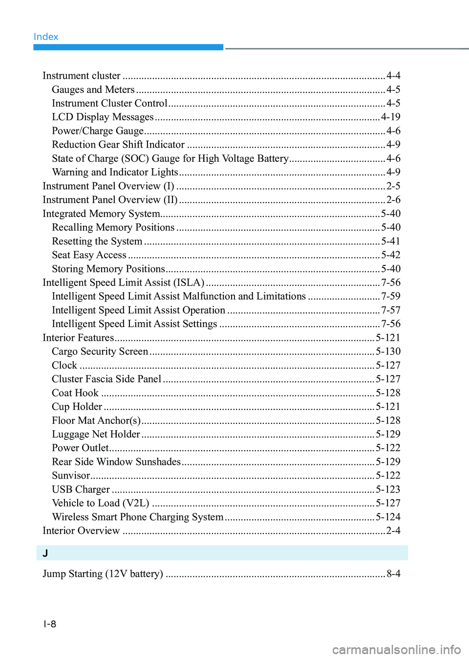
Index
I-8
Instrument cluster .................................................................................................. 4-4
Gauges and Meters ............................................................................................. 4-5
Instrument Cluster Control ................................................................................. 4-5
LCD Display Messages .................................................................................... 4-19
Power/Charge Gauge .......................................................................................... 4-6
Reduction Gear Shift Indicator .......................................................................... 4-9
State of Charge (SOC) Gauge for High Voltage Battery ....................................4-6
Warning and Indicator Lights ............................................................................. 4-9
Instrument Panel Overview (I) .............................................................................. 2-5
Instrument Panel Overview (II) ............................................................................. 2-6
Integrated Memory System.................................................................................. 5-40
Recalling Memory Positions ............................................................................ 5-40
Resetting the System ........................................................................................ 5-41
Seat Easy Access .............................................................................................. 5-42
Storing Memory Positions ................................................................................ 5-40
Intelligent Speed Limit Assist (ISLA) ................................................................. 7-56
Intelligent Speed Limit Assist Malfunction and Limitations ...........................7-59
Intelligent Speed Limit Assist Operation .........................................................7-57
Intelligent Speed Limit Assist Settings ............................................................7-56
Interior Features ................................................................................................. 5-121
Cargo Security Screen .................................................................................... 5-130
Clock .............................................................................................................. 5-127
Cluster Fascia Side Panel ............................................................................... 5-127
Coat Hook ...................................................................................................... 5-128
Cup Holder ..................................................................................................... 5-121
Floor Mat Anchor(s) ....................................................................................... 5-128
Luggage Net Holder ....................................................................................... 5-129
Power Outlet ................................................................................................... 5-122
Rear Side Window Sunshades ........................................................................ 5-129
Sunvisor .......................................................................................................... 5-122
USB Charger .................................................................................................. 5-123
Vehicle to Load (V2L) ................................................................................... 5-127
Wireless Smart Phone Charging System ........................................................5-124
Interior Overview .................................................................................................. 2-4 J
Jump Starting (12V battery) .................................................................................. 8-4