sensor Hyundai Ioniq Plug-in Hybrid 2020 Repair Manual
[x] Cancel search | Manufacturer: HYUNDAI, Model Year: 2020, Model line: Ioniq Plug-in Hybrid, Model: Hyundai Ioniq Plug-in Hybrid 2020Pages: 635, PDF Size: 52.13 MB
Page 452 of 635
6-16
What to do in an emergency
Always check the TPMS malfunction
LCD display after replacing one or
more tires or wheels on your vehicle
to ensure that the replacement or
alternate tires and wheels allow the
TPMS to continue to function proper-
ly.
If any of the below happens, have
the system checked by an author-
ized HYUNDAI dealer.
1. The Low Tire Pressure TPMS
Malfunction Indicator does not
illuminate for 3 seconds when
the Engine Start/Stop button is
placed to the ON position or the
vehicle is in the ready ( )
mode.
2. The TPMS Malfunction Indicator
remains illuminated after blink-
ing for approximately 1 minute.
3. The Low Tire Pressure LCD dis-
play remains illuminated
Low Tire Pressure
Telltale
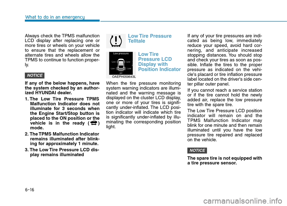
Low Tire
Pressure LCD
Display with
Position Indicator
When the tire pressure monitoring
system warning indicators are illumi-
nated and the warning message is
displayed on the cluster LCD display,
one or more of your tires is signifi-
cantly under-inflated. The LCD posi-
tion indicator will indicate which tire
is significantly under-inflated by illu-
minating the corresponding position
light.If any of your tire pressures are indi-
cated as being low, immediately
reduce your speed, avoid hard cor-
nering, and anticipate increased
stopping distances. You should stop
and check your tires as soon as pos-
sible. Inflate the tires to the proper
pressure as indicated on the vehi-
cle's placard or tire inflation pressure
label located on the driver's side cen-
ter pillar outer panel.
If you cannot reach a service station
or if the tire cannot hold the newly
added air, replace the low pressure
tire with the spare tire.
The Low Tire Pressure LCD position
indicator will remain on and the
TPMS Malfunction Indicator may
blink for one minute and then remain
illuminated until you have the low
pressure tire repaired and replaced
on the vehicle.
The spare tire is not equipped with
a tire pressure sensor.
NOTICE
NOTICEOAEPH059643L
Page 454 of 635
6-18
What to do in an emergency
The TPMS Malfunction Indicator
may illuminate after blinking for
one minute if the vehicle is near
electric power supply cables or
radio transmitters such as police
stations, government and public
offices, broadcasting stations,
military installations, airports,
transmitting towers, etc.
Additionally, the TPMS Malfunction
Indicator may illuminate if snow
chains are used or electronic
devices such as computers, charg-
ers, remote starters, navigation,
etc. This may interfere with normal
operation of the TPMS.
Changing a Tire with TPMS
If you have a flat tire, the Low Tire
Pressure and LCD position indicator
will come on. Have the flat tire
repaired by an authorized HYUNDAI
dealer as soon as possible or
replace the flat tire with the spare
tire.
Never use a puncture-repairing
agent not approved by HYUNDAI
dealer to repair and/or inflate a
low pressure tire. Tire sealant not
approved by HYUNDAI dealer may
damage the tire pressure sensor.
The spare tire does not come with a
tire pressure monitoring sensor.
When the low pressure tire or the flat
tire is replaced with the spare tire,
the Low Tire Pressure LCD position
indicator will remain on. Also, the
TPMS Malfunction Indicator will illu-
minate after blinking for one minute if
the vehicle is driven at speed above
15.5 mph (25 km/h) for approximate-
ly 20 minutes.Once the original tire equipped with
a tire pressure monitoring sensor is
reinflated to the recommended pres-
sure and reinstalled on the vehicle,
the Low Tire Pressure LCD position
indicator and TPMS Malfunction
Indicator will go off within a few min-
utes of driving.
If the indicators do not disappear
after a few minutes, please visit an
authorized HYUNDAI dealer.
Each wheel is equipped with a tire
pressure sensor mounted inside the
tire behind the valve stem (except for
the spare tire). You must use TPMS
specific wheels. It is recommended
that you always have your tires serv-
iced by an authorized HYUNDAI
dealer.
NOTICE
NOTICE
Page 468 of 635
6-32
What to do in an emergency
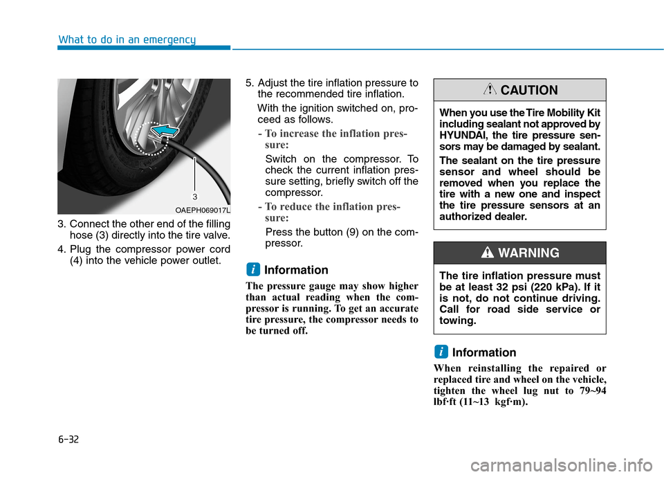
3. Connect the other end of the filling
hose (3) directly into the tire valve.
4. Plug the compressor power cord
(4) into the vehicle power outlet.5. Adjust the tire inflation pressure to
the recommended tire inflation.
With the ignition switched on, pro-
ceed as follows.
- To increase the inflation pres-
sure:
Switch on the compressor. To
check the current inflation pres-
sure setting, briefly switch off the
compressor.
- To reduce the inflation pres-
sure:
Press the button (9) on the com-
pressor.
Information
The pressure gauge may show higher
than actual reading when the com-
pressor is running. To get an accurate
tire pressure, the compressor needs to
be turned off.
Information
When reinstalling the repaired or
replaced tire and wheel on the vehicle,
tighten the wheel lug nut to 79~94
lbf·ft (11~13kgf·m).
i
i
When you use the Tire Mobility Kit
including sealant not approved by
HYUNDAI, the tire pressure sen-
sors may be damaged by sealant.
The sealant on the tire pressure
sensor and wheel should be
removed when you replace the
tire with a new one and inspect
the tire pressure sensors at an
authorized dealer.
CAUTION
The tire inflation pressure must
be at least 32 psi (220 kPa). If it
is not, do not continue driving.
Call for road side service or
towing.
WARNING
OAEPH069017L
Page 475 of 635
6-39
What to do in an emergency
6
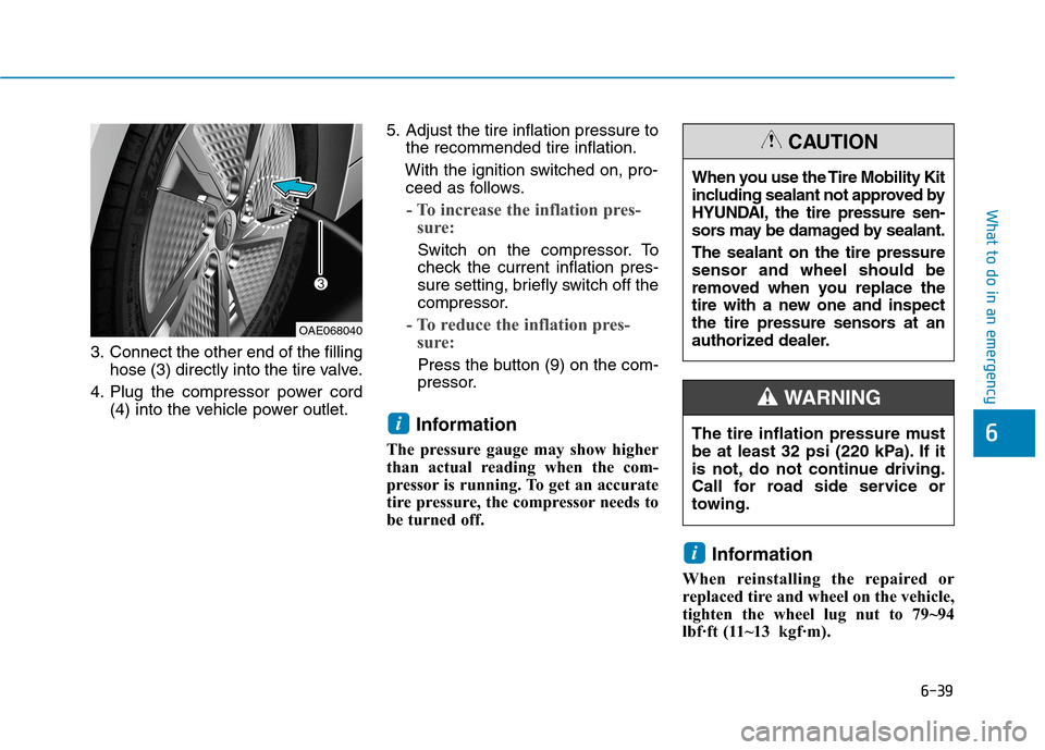
3. Connect the other end of the filling
hose (3) directly into the tire valve.
4. Plug the compressor power cord
(4) into the vehicle power outlet.5. Adjust the tire inflation pressure to
the recommended tire inflation.
With the ignition switched on, pro-
ceed as follows.
- To increase the inflation pres-
sure:
Switch on the compressor. To
check the current inflation pres-
sure setting, briefly switch off the
compressor.
- To reduce the inflation pres-
sure:
Press the button (9) on the com-
pressor.
Information
The pressure gauge may show higher
than actual reading when the com-
pressor is running. To get an accurate
tire pressure, the compressor needs to
be turned off.
Information
When reinstalling the repaired or
replaced tire and wheel on the vehicle,
tighten the wheel lug nut to 79~94
lbf·ft (11~13kgf·m).
i
i
OAE068040
When you use the Tire Mobility Kit
including sealant not approved by
HYUNDAI, the tire pressure sen-
sors may be damaged by sealant.
The sealant on the tire pressure
sensor and wheel should be
removed when you replace the
tire with a new one and inspect
the tire pressure sensors at an
authorized dealer.
CAUTION
The tire inflation pressure must
be at least 32 psi (220 kPa). If it
is not, do not continue driving.
Call for road side service or
towing.
WARNING
Page 505 of 635
7-25
7
Maintenance
Information
If the vehicle is operated in extremely
dusty or sandy areas, replace the ele-
ment more often than the usual rec-
ommended intervals (refer to
"Maintenance Under Severe Usage
Conditions" in this chapter).
Do not drive with the air cleaner
filter removed. This will result in
excessive engine wear.
When removing the air cleaner
filter, be careful that dust or dirt
does not enter the air intake, or
damage may result.
Use HYUNDAI genuine parts.
Use of non-genuine parts could
damage the air flow sensor.
NOTICE
i
Page 548 of 635
7-68
Maintenance
Do not use strong soap, chemi-
cal detergents or hot water, and
do not wash the vehicle in direct
sunlight or when the body of the
vehicle is warm.
Be careful when washing the
side windows of your vehicle.
Especially, with high-pressure
water, water may leak through
the windows and wet the interi-
or.
To prevent damage to the plastic
parts, do not clean with chemi-
cal solvents or strong deter-
gents.
To prevent damage to the charg-
ing door, make sure to close and
lock the vehicle doors when
washing (high-pressure wash-
ing, automatic car washing, etc.)
the vehicle.
High-pressure washing
When using high-pressure wash-
ers, make sure to maintain suffi-
cient distance from the vehicle.
Insufficient clearance or excessive
pressure can lead to component
damage or water penetration.
Do not spray the camera, sensors
or its surrounding area directly with
a high pressure washer. Shock
applied from high pressure water
may cause the device to not oper-
ate normally.
Do not bring the nozzle tip close to
boots (rubber or plastic covers) or
connectors as they may be dam-
aged if they come into contact with
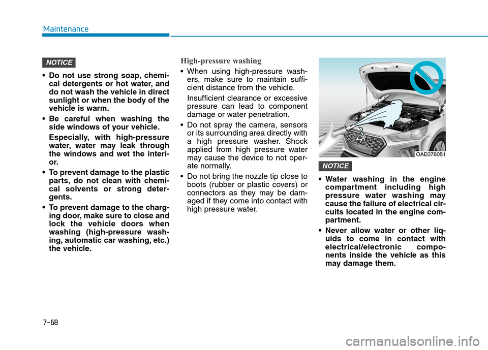
high pressure water. Water washing in the engine
compartment including high
pressure water washing may
cause the failure of electrical cir-
cuits located in the engine com-
partment.
Never allow water or other liq-
uids to come in contact with
electrical/electronic compo-
nents inside the vehicle as this
may damage them.
NOTICE
NOTICE
OAE078051
Page 593 of 635
H22
C CH
HA
AR
RG
GI
IN
NG
G
T
TH
HE
E
P
PL
LU
UG
G-
-I
IN
N
H
HY
YB
BR
RI
ID
D
V
VE
EH
HI
IC
CL
LE
E
(
(C
CO
ON
NT
T.
.)
)
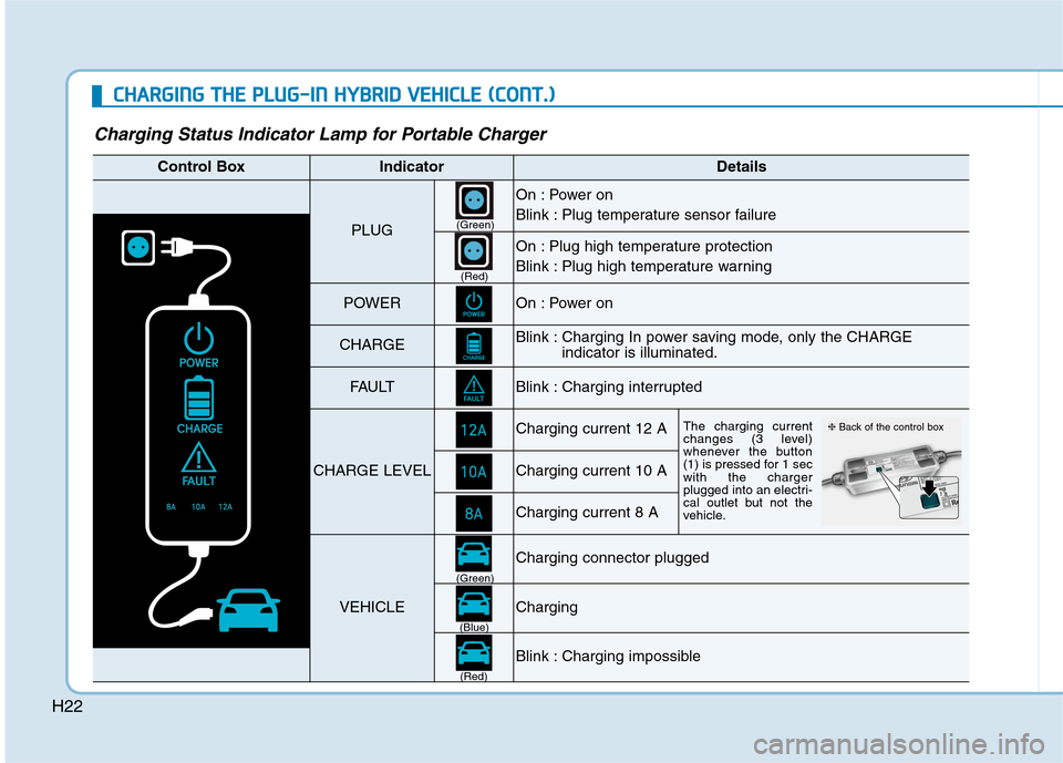
Charging Status Indicator Lamp for Portable Charger
Control BoxIndicatorDetails
PLUG
On : Power on
Blink : Plug temperature sensor failure
On : Plug high temperature protection
Blink : Plug high temperature warning
POWEROn : Power on
CHARGEBlink : Charging In power saving mode, only the CHARGE
indicator is illuminated.
FAU LTBlink : Charging interrupted
CHARGE LEVEL
Charging current 12 AThe charging current
changes (3 level)
whenever the button
(1) is pressed for 1 sec
with the charger
plugged into an electri-
cal outlet but not the
vehicle.
Charging current 10 A
Charging current 8 A
VEHICLE
Charging connector plugged
Charging
Blink : Charging impossible
(Green)
(Green)
(Blue)
(Red)(Red)
❈Back of the control box
Page 594 of 635
H23
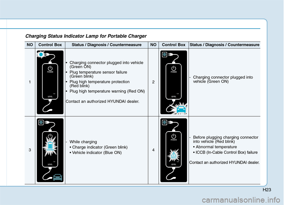
Charging Status Indicator Lamp for Portable Charger
NOControl BoxStatus / Diagnosis / CountermeasureNOControl BoxStatus / Diagnosis / Countermeasure
1
Charging connector plugged into vehicle
(Green ON)
Plug temperature sensor failure
(Green blink)
Plug high temperature protection
(Red blink)
Plug high temperature warning (Red ON)
Contact an authorized HYUNDAI dealer.
2
- Charging connector plugged into
vehicle (Green ON)
3
- While charging
4
- Before plugging charging connector
into vehicle (Red blink)
Contact an authorized HYUNDAI dealer.
Page 595 of 635
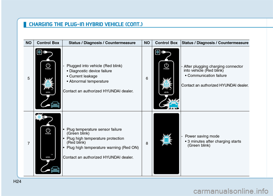
H24
NOControl BoxStatus / Diagnosis / CountermeasureNOControl BoxStatus / Diagnosis / Countermeasure
5
- Plugged into vehicle (Red blink)
Contact an authorized HYUNDAI dealer.
6
- After plugging charging connector
into vehicle (Red blink)
Contact an authorized HYUNDAI dealer.
7
Plug temperature sensor failure
(Green blink)
Plug high temperature protection
(Red blink)
Plug high temperature warning (Red ON)
Contact an authorized HYUNDAI dealer.
8
- Power saving mode
(Green blink)
C CH
HA
AR
RG
GI
IN
NG
G
T
TH
HE
E
P
PL
LU
UG
G-
-I
IN
N
H
HY
YB
BR
RI
ID
D
V
VE
EH
HI
IC
CL
LE
E
(
(C
CO
ON
NT
T.
.)
)
Page 630 of 635
I-4
Engine oil ........................................................................7-16
Checking the Engine Oil and Filter ...........................7-17
Checking the Engine Oil Level ..................................7-16
Engine Start/Stop Button ..................................................5-6
Explanation of scheduled maintenance items.................7-14
Exterior features..............................................................3-49
Fuel Filler Door (Hybrid vehicle) ..............................3-52
Fuel Filler Door (Plug-in hybrid vehicle) ..................3-55
Hood ...........................................................................3-49
Liftgate .......................................................................3-50
Forward Collision-Avoidance Assist (FCA)
- front view camera only ..............................................5-47
FCA sensor (Front view camera) ...............................5-52
FCA Warning Message and Brake Control ................5-49
Limitations of the System ..........................................5-55
System malfunction ....................................................5-53
System Setting and Activation ...................................5-47
Forward Collision-Avoidance Assist (FCA)
- sensor fusion...............................................................5-61
FCA Sensor (Front view camera+ Front radar) .........5-66
FCA Warning Message and Brake control.................5-63
Limitations of the System ..........................................5-70
System Malfunction ...................................................5-68
System Setting and Activation ...................................5-61
Forward/Reverse Parking Distance Warning (PDW) ..3-138
Self-Diagnosis ..........................................................3-142Fuses ...............................................................................7-49
Engine Compartment Panel Fuse Replacement .........7-52
Fuse/Relay Panel Description ....................................7-53
Instrument Panel Fuse Replacement ..........................7-50
Hazard warning flasher .....................................................6-2
Highway Driving Assist (HDA) ...................................5-141
System Setting and Operation ..................................5-141
Warning Message .....................................................5-144
Hybrid Starter & Generator (HSG) belt .........................7-21
Checking the Hybrid Starter & Generator (HSG)
Belt ...........................................................................7-21
Hybrid Vehicle........................................................................
Engine Compartment....................................................1-6
Exterior Overview ........................................................1-2
Instrument Panel Overview ..........................................1-5
Interior Overview .........................................................1-4
If an accident occurs .......................................................6-44
If the 12 volt Battery is discharged (Hybrid Vehicle) ......6-5
Before Jump Starting....................................................6-5
Jump Starting................................................................6-6
If the 12 volt battery is discharged
(Plug-In Hybrid Vehicle) ................................................6-9
Jump Starting................................................................6-9
Index
F
H
I