open gas tank Hyundai Kona 2018 Owner's Manual - RHD (UK, Australia)
[x] Cancel search | Manufacturer: HYUNDAI, Model Year: 2018, Model line: Kona, Model: Hyundai Kona 2018Pages: 497, PDF Size: 11.7 MB
Page 113 of 497

3-35
Convenient features of your vehicle
3
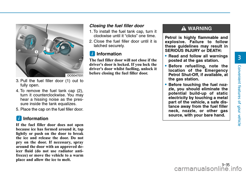
3. Pull the fuel filler door (1) out tofully open.
4. To remove the fuel tank cap (2), turn it counterclockwise. You may
hear a hissing noise as the pres-
sure inside the tank equalizes.
5. Place the cap on the fuel filler door.
Information
If the fuel filler door does not open
because ice has formed around it, tap
lightly or push on the door to break
the ice and release the door. Do not
pry on the door. If necessary, spray
around the door with an approved de-
icer fluid (do not use radiator anti-
freeze) or move the vehicle to a warm
place and allow the ice to melt.
Closing the fuel filler door
1. To install the fuel tank cap, turn it clockwise until it “clicks” one time.
2. Close the fuel filler door until it is latched securely.
Information
The fuel filler door will not close if the
driver's door is locked. If you lock the
driver's door whilst fuelling, unlock it
before closing the fuel filler door.
i
i
OOS047031
Petrol is highly flammable and
explosive. Failure to follow
these guidelines may result in
SERIOUS INJURY or DEATH:
•Read and follow all warnings
posted at the gas station.
•Before refuelling, note the
location of the Emergency
Petrol Shut-Off, if available, at
the gas station.
•Before touching the fuel noz-
zle, you should eliminate the
potential build-up of static
electricity by touching a metal
part of the vehicle, a safe dis-
tance away from the fuel filler
neck, nozzle, or other gas
source, with your bare hand.
WARNING
Page 483 of 497

7-76
Maintenance
1. Crankcase emission controlsystem
The positive crankcase ventilation
system is employed to prevent air
pollution caused by blow-by gases
being emitted from the crankcase.
This system supplies fresh filtered air
to the crankcase through the air
intake hose. Inside the crankcase,
the fresh air mixes with blow-by
gases, which then pass through the
PCV valve into the induction system.
2. Evaporative emission con-trol system
The Evaporative Emission Control
System is designed to prevent fuel
vapours from escaping into the
atmosphere.
Canister
Fuel vapours generated inside the
fuel tank are absorbed and stored in
the onboard canister. When the
engine is running, the fuel vapours
absorbed in the canister are drawn
into the surge tank through the purge
control solenoid valve.
Purge Control Solenoid Valve
(PCSV)
The purge control solenoid valve is
controlled by the Engine Control
Module (ECM); when the engine
coolant temperature is low during
idling, the PCSV closes so that evap-
orated fuel is not taken into the
engine. After the engine warms-up
during ordinary driving, the PCSV
opens to introduce evaporated fuel to
the engine.
3. Exhaust emission control system
The Exhaust Emission Control System
is a highly effective system which con-
trols exhaust emissions whilst main-
taining good vehicle performance.