Cluster Hyundai Matrix 2003 Owner's Manual
[x] Cancel search | Manufacturer: HYUNDAI, Model Year: 2003, Model line: Matrix, Model: Hyundai Matrix 2003Pages: 312, PDF Size: 4.1 MB
Page 34 of 312
FEATURES OF YOUR HYUNDAI
1- 26 parts. If the liquid from the air freshener does leak onto these areas, wash them withwater immediately. WARNING:
o When the SRS is activated, there may be
a loud noise and fine dust will be re-leased throughout the vehicle. These con-ditions are normal and are not hazard-ous. However, the fine dust generatedduring airbag deployment may causeskin irritation. Wash your hands and facethoroughly with lukewarm water and amild soap after an accident in which theairbags were deployed.
o The SRS can function only when the ignition key is in the "ON" position. If theSRS SRI does not come on, or continu-ously remains on, after flashing for about6 seconds when the ignition key is turnedto the "ON" position, or after the engineis started, comes on while driving, theSRS is not working properly. If this oc-curs, have your vehicle immediately in-spected by your Hyundai dealer.
o Before you replace a fuse or disconnect a battery terminal, turn the ignition key tothe "LOCK" position or remove the igni-tion key. Never remove or replace the airbag related fuse(s) when the ignition keyis in the "ON" position. Failure to heedthis warning will cause the SRS SRI toilluminate.
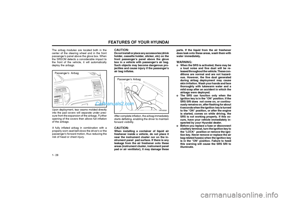
Passenger's Airbag
YR10353A
After complete inflation, the airbag immediately starts deflating, enabling the driver to maintainforward visibility. CAUTION: When installing a container of liquid airfreshener inside a vehicle, do not place itnear the instrument cluster nor on the in-strument panel pad surface. If there is anyleakage from the air freshener onto theseareas (instrument cluster, instrument panelpad or air ventilator), it may damage these
CAUTION:Do not install or place any accessories (drinkholder, cassette holder, sticker, etc) on thefront passenger's panel above the glovebox in a vehicle with passenger's air bag.Such objects may become dangerous pro-jectiles and cause injury if the passenger'sair bag inflates.
Passenger's Airbag
The airbag modules are located both in the center of the steering wheel and in the frontpassenger's panel above the glove box. Whenthe SRSCM detects a considerable impact tothe front of the vehicle, it will automaticallydeploy the airbags.
Upon deployment, tear seams molded directlyinto the pad covers will separate under pres-sure from the expansion of the airbags. Furtheropening of the covers then allows full inflationof the airbags. A fully inflated airbag in combination with a properly worn seat belt slows the driver's or thepassenger's forward motion, thus reducing therisk of head or chest injury.
B240B04FC
Page 37 of 312
FEATURES OF YOUR HYUNDAI 1- 29
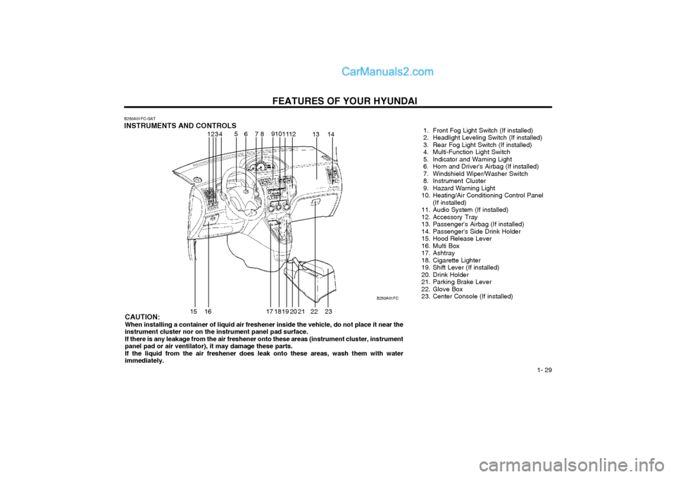
B250A01FC-GAT INSTRUMENTS AND CONTROLS
1. Front Fog Light Switch (If installed)
2. Headlight Leveling Switch (If installed)
3. Rear Fog Light Switch (If installed)
4. Multi-Function Light Switch
5. Indicator and Warning Light
6. Horn and Driver's Airbag (If installed)
7. Windshield Wiper/Washer Switch
8. Instrument Cluster
9. Hazard Warning Light
10. Heating/Air Conditioning Control Panel
(If installed)
11. Audio System (If installed)
12. Accessory Tray
13. Passenger's Airbag (If installed)
14. Passenger's Side Drink Holder
15. Hood Release Lever
16. Multi Box
17. Ashtray
18. Cigarette Lighter
19. Shift Lever (If installed)
20. Drink Holder
21. Parking Brake Lever
22. Glove Box
23. Center Console (If installed)
CAUTION:When installing a container of liquid air freshener inside the vehicle, do not place it near theinstrument cluster nor on the instrument panel pad surface.If there is any leakage from the air freshener onto these areas (instrument cluster, instrumentpanel pad or air ventilator), it may damage these parts.If the liquid from the air freshener does leak onto these areas, wash them with waterimmediately. B250A01FC
12
3
4 5
678 910
1112
13 14
15 16 17 18 19 20 21 22 23
Page 38 of 312
FEATURES OF YOUR HYUNDAI
1- 30
B260A01FC-GAT
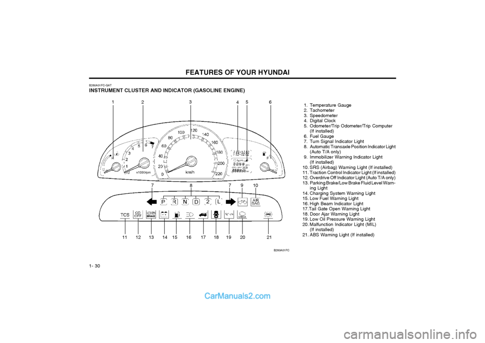
INSTRUMENT CLUSTER AND INDICATOR (GASOLINE ENGINE) 1. Temperature Gauge
2. Tachometer
3. Speedometer
4. Digital Clock
5. Odometer/Trip Odometer/Trip Computer(If installed)
6. Fuel Gauge
7. Turn Signal Indicator Light
8. Automatic Transaxle Position Indicator Light (Auto T/A only)
9. Immobilizer Warning Indicator Light (If installed)
10. SRS (Airbag) Warning Light (If installed)
11. Traction Control Indicator Light (If installed)
12. Overdrive Off Indicator Light (Auto T/A only)
13. Parking Brake/Low Brake Fluid Level Warn- ing Light
14. Charging System Warning Light
15. Low Fuel Warning Light
16. High Beam Indicator Light17.Tail Gate Open Warning Light
18. Door Ajar Warning Light
19. Low Oil Pressure Warning Light
20. Malfunction Indicator Light (MIL) (If installed)
21. ABS Warning Light (If installed)
B260A01FC
1
2 3
45
6
7 8 9
10
11 12 13 14 15 16 17 18 19 20 21 7
Page 39 of 312
FEATURES OF YOUR HYUNDAI 1- 31
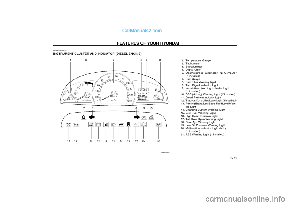
B260B01FC-GAT INSTRUMENT CLUSTER AND INDICATOR (DIESEL ENGINE)
1. Temperature Gauge
2. Tachometer
3. Speedometer
4. Digital Clock
5. Odometer/Trip Odometer/Trip Computer(If installed)
6. Fuel Gauge
7. Fuel Filter Warning Light
8. Turn Signal Indicator Light
9. Immobilizer Warning Indicator Light (If installed)
10. SRS (Airbag) Warning Light (If installed)
11. Diesel Pre-heat Indicator Light
12. Traction Control Indicator Light (If installed)
13. Parking Brake/Low Brake Fluid Level Warn- ing Light
14. Charging System Warning Light
15. Low Fuel Warning Light
16. High Beam Indicator Light
17. Tail Gate Open Warning Light
18. Door Ajar Warning Light
19. Low Oil Pressure Warning Light
20. Malfunction Indicator Light (MIL) (If installed)
21. ABS Warning Light (If installed)
B260B01FC
1 23 45
6
7 8
910
8
11 12 13 14 15 16 17 18 19 20 21
Page 106 of 312
DRIVING YOUR HYUNDAI 2- 9
an anti-lock braking system may be longer than for those without it in the following road conditions.
o Driving on rough, gravel or snow-covered
roads.
o Driving with tire chains installed.
o Driving on roads where the road surface is pitted or has different surface height.
During these conditions, the vehicle shouldbe driven at reduced speeds. The safety fea- tures of an ABS equipped vehicle should not be tested by high speed driving or cornering. This could endanger the safety of yourself or others. C300A01O-GAT BRAKE TRACTION CONTROL SYSTEM (BTCS) (If Installed) On slippery road surfaces, the traction control system (TCS) limits the drive wheels from spin- ning excessively, thus helping the car to acceler- ate. It also provides sufficient driving force and steering performance as the car turns at acceler- ated speeds. SLIP Control Limits the drive wheels from spinning exces- sively during starting or while making accelerat- ed turns on slippery roads to avoid losing the driving force of the front wheels. C300B01O-GAT TCS ON ModeIn the TCS ON mode, the indicator in the instru- ment cluster will not be illuminated. NOTE:
1) Turn off the engine. Then restart the en-
gine, and the TCS mode will automaticallyturn "ON".
2) When the traction control is operating
properly, you can feel a slight pulsation in the vehicle. This is only the effect of brake control and indicates nothing unusual. C300D02O-GAT Indicator and Warning The indicator should illuminate when the ignition key is turned to "ON" or "START", but should go out after three seconds. If the indicator does not illuminate, have it checked by an authorized Hyundai dealer. Should there be any unusual conditions in the device, TCS illuminates as a warning. If TCS illuminates, pull your car to a safe place and stop the engine. Then, start the engine again to check if the TCS indicator goes out. If the indicator remains lit even after the engine has been started, have your car checked by an authorized Hyundai dealer. NOTE: When TCS illuminates, traction control is automatically deactivated for safety.
Driving hints TCS does not actively apply brakes. Be sure to decelerate the car sufficiently before entering curves. CAUTION: When the TCS indicator blinks, SLIP control has been activated. It also means that the road is slippery or your car is accelerating excessively. In this situation, release foot pressure from the accelerator pedal and main- tain moderate speed. WARNING: Traction control is only a driving aid; all normal precautions for driving in inclement weather and on slippery driving surfaces should be observed.
3) When the engine starts, a click is heard
from the engine compartment; however, this is only the sound of traction control being checked.
4) When moving out of the mud or fresh
snow, pressing the accelerator pedal may not cause the engine speed to increase.
Page 159 of 312

DO-IT-YOURSELF MAINTENANCE
6-26
G200C02FC-GAT
FUSE PANEL DESCRIPTION Engine Compartment (GASOLINE)
HFC4004
PROTECTED COMPONENTS Generator (A/CON, RR HTD, STOP, D/LOCK, HAZARD) Fuse Generator, Engine control relay, ECM Radiator fan relay Start relay, Ignition switch Blower relay Power window relay Condenser fan relay #1 ABS control module, ABS bleeding connector ABS control module, ABS bleeding connector Fuel pump relay Injector, lgnition coilMAP sensor, Oxygen sensor, CP sensor, Knock sensor, Throttle position sensor Audio, Room lamp, Overhead console lamp, lnstrument cluster DRL control module Horn relay A/C relay Front fog lamp relay ECM, TCM Tail lamp relay Left rear combi lamp, Left position lamp, Left License lamp Right rear combi lamp, Right position lamp, Right License lamp Left head lamp Right head lamp, (H/LP IND) Fuse
FUSE RATING
120A40A30A 20A 40A 40A 30A 20A 30A 30A 10A 15A 10A 10A 15A 10A 10A 15A 10A 20A 10A 10A 15A 15A
DESCRIPTION
ALTB+
ECU RAD IGN
BLR
P/WINCOND ABSABS
F/PUMP INJ
SNSR
ROOM LP DRL
HORN
A/CON
FR FOG ECU
LP
TAIL LH
TAIL RH H/LP LH
H/LP RH
NOTE:
Not all fuse panel descriptions in this manual may be applicable
to your vehicle. It is accurate at the time of printing. When you inspect the fuse box on your vehicle, refer to the fuse box label.
Page 160 of 312

DO-IT-YOURSELF MAINTENANCE 6-27
DESCRIPTION
ALTB+
ECU RAD IGN
BLR
P/WINCOND ABSABS
F/PUMP ECU ECU
SNSR
ROOM LP DRL
HORN
A/CON
FR FOG
ECULP
TAIL LH
TAIL RH H/LP LH
H/LP RH
G200E01FC-GAT
Engine Compartment (DIESEL)
G200E01FCPROTECTED COMPONENTS Generator (A/CON, RR HTD, STOP, D/LOCK, HAZARD) Fuse Generator, Engine control relay, ECM Radiator fan relay Start relay, Ignition switch Blower relay Power window relay Condenser fan relay #1 ABS control module, ABS bleeding connector ABS control module, ABS bleeding connector Fuel pump relay ECM No.5 (Batt+) ECM No.4 (Batt+)
Glow plug r elay, Assistor h eater relay 1/2, Stop lamp switch,
TDC sensor, EGR act, Throttle plate a ct
Audio, Room lamp, Overhead console lamp, lnstrument cluster, ETACM, Luggage lamp DRL control module Horn relay A/C relay Front fog lamp relay ECM, TCM Tail lamp relay Left rear combi lamp, Left position lamp, Left License lamp Right rear combi lamp, Right position lamp, Right License lamp Left head lamp Right head lamp, (H/LP IND) Fuse
FUSE RATING
100A40A 30A 20A 40A 40A 30A 20A 30A 30A 10A 20A 10A 10A 10A 15A 10A 10A 15A 10A 20A 10A 10A 15A 15A
NOTE:
Not all fuse panel descriptions in this manual may be applicable
to your vehicle. It is accurate at the time of printing. When you inspect the fuse box on your vehicle, refer to the fuse box label.
Page 161 of 312
DO-IT-YOURSELF MAINTENANCE
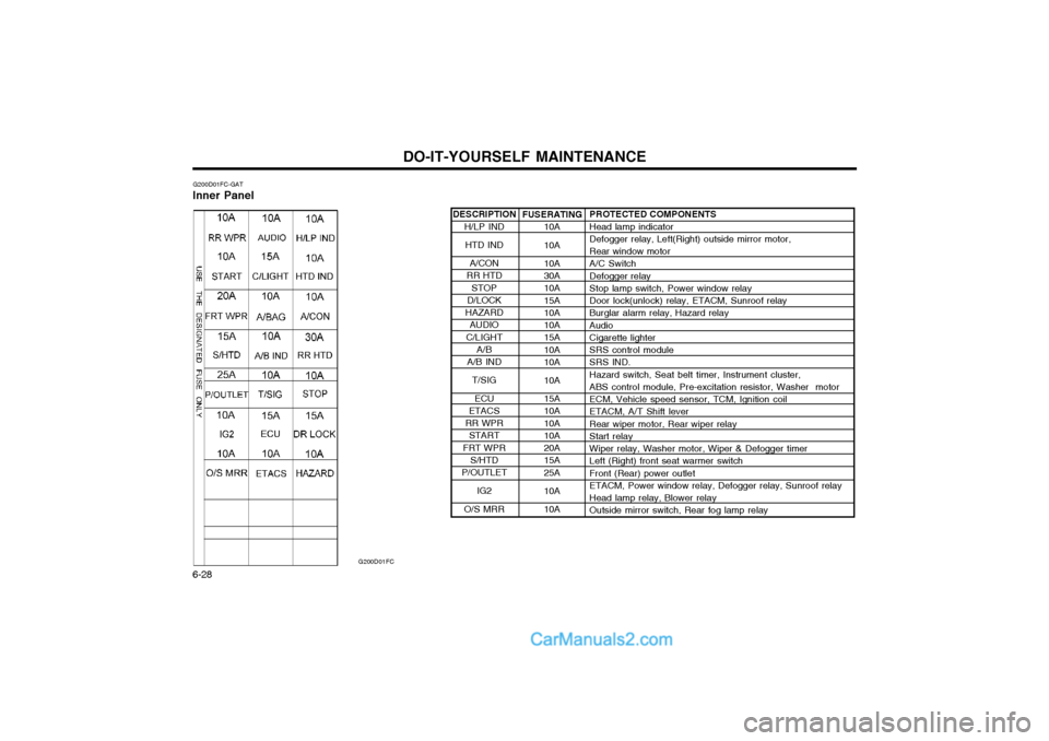
6-28 DESCRIPTION
H/LP IND
HTD IND
A/CON
RR HTD
STOP
D/LOCK
HAZARD AUDIO
C/LIGHT A/B
A/B IND
T/SIG
ECU
ETACS
RR WPR START
FRT WPR S/HTD
P/OUTLET
IG2
O/S MRR
G200D01FC-GAT
Inner Panel
G200D01FC
PROTECTED COMPONENTS Head lamp indicator Defogger relay, Left(Right) outside mirror motor, Rear window motor A/C Switch Defogger relay Stop lamp switch, Power window relay Door lock(unlock) relay, ETACM, Sunroof relay Burglar alarm relay, Hazard relay Audio Cigarette lighter SRS control module SRS IND. Hazard switch, Seat belt timer, Instrument cluster, ABS control module, Pre-excitation resistor, Washer motor ECM, Vehicle speed sensor, TCM, Ignition coil ETACM, A/T Shift lever Rear wiper motor, Rear wiper relay Start relay Wiper relay, Washer motor, Wiper & Defogger timer Left (Right) front seat warmer switch Front (Rear) power outlet ETACM, Power window relay, Defogger relay, Sunroof relay Head lamp relay, Blower relay Outside mirror switch, Rear fog lamp relay
FUSERATING
10A 10A 10A 30A 10A 15A 10A 10A 15A 10A 10A 10A 15A 10A 10A 10A 20A 15A 25A 10A 10A
Page 171 of 312
INDEX
10-2 Driving
Economical dr iving ........................................................................ 2-10
Smooth cornering .......................................................................... 2-10
Winter driving ................................................................................ 2-10
E Emissions Control Systems ................................................................ 7-1
Engine Before starting the engine ............................................................... 2-2Compartment .......................................................................... 6-1 ~ 6-3
Coolant ................................................................................. 6-8 ~ 6-10
Coolant temperature gauge ........................................................... 1-35
If the engine overheats ................................................................... 3-2
Number ............................................................................................ 8-1
Oil ........................................................................................... 6-4 ~ 6-5Starting ............................................................................................ 2-3
Engine Exhaust Can Be Dangerous ................................................... 2-1
FFold-up Tray ...................................................................................... 1-49
Front Fog Light Sw itch ...................................................................... 1-41
Front Seats Adjustable front seats ..................................................................... 1-9
Lumbar support control ................................................................. 1-10
Seat cushion height adjustment .................................................... 1-10
Fuel Capacity .......................................................................................... 9-1
Gauge ............................................................................................ 1-35
Recommendations ........................................................................... 1-1
Fuel Filler Lid
Remote release ............................................................................. 1-51
Fuse Panel Description .......................................................... 6-26 ~ 6-28
Fuses ...................................................................................... 6-19 ~6-20 GGeneral Checks
.................................................................................. 6-4
Glove box .......................................................................................... 1-46
H Hazard Warning System ................................................................... 1-40
Headlight Aiming Adjustment ........................................................... 6-23
Headlight Bulb ................................................................................... 6-23
Headlight Leveling Device System ........................................ 1-43 ~ 1-44
Heating and Ventilation
Air flow control .............................................................................. 1-57
Air intake control ........................................................................... 1-56
Bi-level heating .............................................................................. 1-58
Fan speed control ......................................................................... 1-56
Heating controls ............................................................................ 1-58
Temperature control ...................................................................... 1-58
High-mounted Rear Stoplight ............................................................ 1-49
Hood Release ................................................................................... 1-50
Horn .................................................................................................. 1-54
IIgnition Switch ..................................................................................... 2-2
Immobilizer System ............................................................................. 1-3
Instrument Cluster and Indicator ............................................ 1-30 ~ 1-34
Instruments and Controls .................................................................. 1-29
Interior Light Interior light ................................................................................... 1-46
Map light ........................................................................................ 1-45
Intermittent Wiper .............................................................................. 1-40
JJump Starting ...................................................................................... 3-1
Page 204 of 312

1- 23
CONTROLS AND EQUIPMENT
WARNING:
o When the SRS is activated, there maybe a loud noise and fine dust will be released throughout the vehicle. Theseconditions are normal and are not haz-ardous. However, the fine dust generat-ed during airbag deployment may causeskin irritation. Be sure to wash yourhands and face thoroughly with luke-warm water and a mild soap after anaccident in which the airbags were de-ployed.
o The SRS can function only when the ignition key is in the "ON" position. Ifthe SRS SRI does not come on, orcontinuously remains on, after flashingfor about 6 seconds when the ignitionkey is turned to the "ON" position, orafter the engine is started, or comes onwhile driving, the SRS is not workingproperly. If this occurs, have your ve-hicle immediately inspected by yourHyundai dealer.
o Before you replace a fuse or disconnect a battery terminal, turn the ignition keyto the "LOCK" position or remove theignition key. Never remove or replacethe air bag related fuse(s) when theignition key is in the "ON" position.Failure to heed this warning will causethe SRS SRI to illuminate.
Passenger's Airbag
After complete inflation, the airbag immedi- ately starts deflating, enabling the driver tomaintain forward visibility. CAUTION: When installing a container of liquid air freshener inside a vehicle, do not place itnear the instrument cluster nor on theinstrument panel pad surface. If there isany leakage from the air freshener ontothese areas (instrument cluster, instrumentpanel pad or air ventilator), it may damagethese parts. If the liquid from the air fresh-ener does leak onto these areas, washthem with water immediately. YR10353A
dangerous projectiles and cause injury ifthe passenger's side air bag inflates.
B990B04Y-EAT
Side Impact Airbag
Your Hyundai is equipped with a side impact airbag in each front seat. The purpose of theairbag is to provide the vehicle's driver and/orthe front passenger with additional protectionthan that offered by the seat belt alone. Theside impact airbags are designed to deployonly during certain side impact collisions, de-pending on the crash severity, angle, speedand point of impact. The air bags are notdesigned to deploy in all side impact situa-tions. B990B02Y