sensor Hyundai Matrix 2003 Owner's Manual
[x] Cancel search | Manufacturer: HYUNDAI, Model Year: 2003, Model line: Matrix, Model: Hyundai Matrix 2003Pages: 312, PDF Size: 4.1 MB
Page 31 of 312

FEATURES OF YOUR HYUNDAI 1- 23
CAUTION:
o Because the sensor that activates the
SRS airbag is connected with the pre-tensioner seat belt, the SRS airbag warn-ing light on the instrument panel willblink for approximately 6 seconds afterthe ignition key has been turned to the"ON" position, and then it should turnoff.
o If the pre-tensioner seat belt is not work- ing properly, this warning light will illu-minate even if there is no malfunction ofthe SRS airbag system . If the SRS airbagwarning light does not illuminate whenthe ignition key is turned to "ON", or if itremains illuminated after blinking forapproximately 6 seconds, or if it illumi-nates while the vehicle is being driven,please have an authorized Hyundai deal-er inspect the pre-tensioner seat belt orSRS airbag system as soon as possible. WARNING:
o Pre-tensioners are designed to operate
only one time. After activation, pre-tensioner seat belts must be replaced.All seat belts, of any type, should alwaysbe replaced after they have been wornduring a collision.
o The pre-tensioner seat belt assembly mechanisms become hot during activa-tion. Do not touch the pre-tensioner seatbelt assemblies for several minutes afterthey have been activated.
o Do not attempt to inspect or replace the pre-tensioner seat belts yourself. Thismust be done by an authorized Hyundaidealer.
o Do not strike the pre-tensioner seat belt assemblies.
o Do not attempt to service or repair the pre-tensioner seat belt system in anymanner.
o Improper handling of the pre-tensioner seat belt assemblies, and failure to heedthe warnings to not strike, modify, in-spect, replace, service or repair the pre-tensioner seat belt assemblies may leadto improper operation or inadvertent ac-tivation and serious injury.
o Always wear the seat belts when driving or riding in a motor vehicle.
NOTE:
o Both the driver's and front passenger's pre-tensioner seat belts will be activatedin certain frontal collisions. The pre-tensioner seat belts can be activatedwith the airbags. The pre-tensioners willbe activated under these conditions evenif the seat belts are not being worn at thetime of the collision.
o When the pre-tensioner seat belts are activated, a loud noise may be heard andfine dust, which may appear to be smoke,may be visible in the passenger compart-ment. These are normal operating condi-tions and are not hazardous.
o Although it is harmless, the fine dust may cause skin irritation and should notbe breathed for prolonged periods. Washyour hands and face thoroughly after anaccident in which the pre-tensioner seatbelts were activated.
Page 35 of 312

FEATURES OF YOUR HYUNDAI 1- 27
o Do not place any objects over the airbagor between the airbag and yourself.
o Do not place any objects (an umbrella, bag, etc.) between the front door and the front seat. Such objects may becomedangerous projectiles and cause injury ifthe supplemental side impact air baginflates.
o To prevent unexpected deployment of the side impact air bag that may result inpersonal injury, avoid impact to the sideairbag sensor when the ignition key ison.
B240C03Y-GAT SRS CareThe SRS is virtually maintenance-free and there are no parts you can safely service byyourself. The entire SRS system must be in-spected by an authorized Hyundai dealer 10years after the date that the vehicle was manu-factured. Any work on the SRS system, such as remov- ing, installing, repairing, or any work on thesteering wheel must be performed by a quali-fied Hyundai technician. Improper handling ofthe SRS system may result in serious personalinjury.
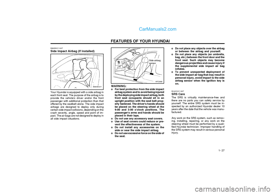
HFC2092
Side airbag sensor
WARNING:
o For best protection from the side impact airbag system and to avoid being injuredby the deploying side impact airbag, bothfront seat occupants should sit in anupright position with the seat belt prop-erly fastened. The driver's hands shouldbe placed on the steering wheel at the9:00 and 3:00 o'clock positions. Thepassenger's arms and hands should beplaced in their laps.
o Do not use any accessory seat covers.
o Use of seat covers could reduce or pre- vent the effectiveness of the system.
o Do not install any accessories on the side or near the side impact airbag.
o Do not use excessive force on the side of the seat.
B990B03Y-GAT Side Impact Airbag (If Installed)B990B02Y
Your Hyundai is equipped with a side airbag in each front seat. The purpose of the airbag is toprovide the vehicle's driver and/or the frontpassenger with additional protection than thatoffered by the seatbelt alone. The side impactairbags are designed to deploy only duringcertain side impact collisions, depending on thecrash severity, angle, speed and point of im-pact. The air bags are not designed to deploy inall side impact situations.
Page 159 of 312

DO-IT-YOURSELF MAINTENANCE
6-26
G200C02FC-GAT
FUSE PANEL DESCRIPTION Engine Compartment (GASOLINE)
HFC4004
PROTECTED COMPONENTS Generator (A/CON, RR HTD, STOP, D/LOCK, HAZARD) Fuse Generator, Engine control relay, ECM Radiator fan relay Start relay, Ignition switch Blower relay Power window relay Condenser fan relay #1 ABS control module, ABS bleeding connector ABS control module, ABS bleeding connector Fuel pump relay Injector, lgnition coilMAP sensor, Oxygen sensor, CP sensor, Knock sensor, Throttle position sensor Audio, Room lamp, Overhead console lamp, lnstrument cluster DRL control module Horn relay A/C relay Front fog lamp relay ECM, TCM Tail lamp relay Left rear combi lamp, Left position lamp, Left License lamp Right rear combi lamp, Right position lamp, Right License lamp Left head lamp Right head lamp, (H/LP IND) Fuse
FUSE RATING
120A40A30A 20A 40A 40A 30A 20A 30A 30A 10A 15A 10A 10A 15A 10A 10A 15A 10A 20A 10A 10A 15A 15A
DESCRIPTION
ALTB+
ECU RAD IGN
BLR
P/WINCOND ABSABS
F/PUMP INJ
SNSR
ROOM LP DRL
HORN
A/CON
FR FOG ECU
LP
TAIL LH
TAIL RH H/LP LH
H/LP RH
NOTE:
Not all fuse panel descriptions in this manual may be applicable
to your vehicle. It is accurate at the time of printing. When you inspect the fuse box on your vehicle, refer to the fuse box label.
Page 160 of 312

DO-IT-YOURSELF MAINTENANCE 6-27
DESCRIPTION
ALTB+
ECU RAD IGN
BLR
P/WINCOND ABSABS
F/PUMP ECU ECU
SNSR
ROOM LP DRL
HORN
A/CON
FR FOG
ECULP
TAIL LH
TAIL RH H/LP LH
H/LP RH
G200E01FC-GAT
Engine Compartment (DIESEL)
G200E01FCPROTECTED COMPONENTS Generator (A/CON, RR HTD, STOP, D/LOCK, HAZARD) Fuse Generator, Engine control relay, ECM Radiator fan relay Start relay, Ignition switch Blower relay Power window relay Condenser fan relay #1 ABS control module, ABS bleeding connector ABS control module, ABS bleeding connector Fuel pump relay ECM No.5 (Batt+) ECM No.4 (Batt+)
Glow plug r elay, Assistor h eater relay 1/2, Stop lamp switch,
TDC sensor, EGR act, Throttle plate a ct
Audio, Room lamp, Overhead console lamp, lnstrument cluster, ETACM, Luggage lamp DRL control module Horn relay A/C relay Front fog lamp relay ECM, TCM Tail lamp relay Left rear combi lamp, Left position lamp, Left License lamp Right rear combi lamp, Right position lamp, Right License lamp Left head lamp Right head lamp, (H/LP IND) Fuse
FUSE RATING
100A40A 30A 20A 40A 40A 30A 20A 30A 30A 10A 20A 10A 10A 10A 15A 10A 10A 15A 10A 20A 10A 10A 15A 15A
NOTE:
Not all fuse panel descriptions in this manual may be applicable
to your vehicle. It is accurate at the time of printing. When you inspect the fuse box on your vehicle, refer to the fuse box label.
Page 161 of 312

DO-IT-YOURSELF MAINTENANCE
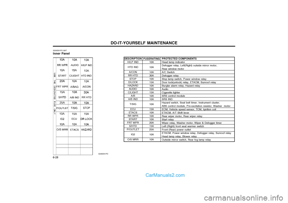
6-28 DESCRIPTION
H/LP IND
HTD IND
A/CON
RR HTD
STOP
D/LOCK
HAZARD AUDIO
C/LIGHT A/B
A/B IND
T/SIG
ECU
ETACS
RR WPR START
FRT WPR S/HTD
P/OUTLET
IG2
O/S MRR
G200D01FC-GAT
Inner Panel
G200D01FC
PROTECTED COMPONENTS Head lamp indicator Defogger relay, Left(Right) outside mirror motor, Rear window motor A/C Switch Defogger relay Stop lamp switch, Power window relay Door lock(unlock) relay, ETACM, Sunroof relay Burglar alarm relay, Hazard relay Audio Cigarette lighter SRS control module SRS IND. Hazard switch, Seat belt timer, Instrument cluster, ABS control module, Pre-excitation resistor, Washer motor ECM, Vehicle speed sensor, TCM, Ignition coil ETACM, A/T Shift lever Rear wiper motor, Rear wiper relay Start relay Wiper relay, Washer motor, Wiper & Defogger timer Left (Right) front seat warmer switch Front (Rear) power outlet ETACM, Power window relay, Defogger relay, Sunroof relay Head lamp relay, Blower relay Outside mirror switch, Rear fog lamp relay
FUSERATING
10A 10A 10A 30A 10A 15A 10A 10A 15A 10A 10A 10A 15A 10A 10A 10A 20A 15A 25A 10A 10A
Page 201 of 312

CONTROLS AND EQUIPMENT
1- 20 pre-tensioner seat belt or SRS airbag system as soon as possible.
WARNING:
o Pre-tensioners are designed to operate only one time. After activation, pre-tensioner seat belts must be replaced.All seat belts, of any type, should al-ways be replaced after they have beenworn during a collision.
o The pre-tensioner seat belt assembly mechanisms become hot during activa-tion. Do not touch the pre-tensionerseat belt assemblies for several min-utes after they have been activated.
o Do not attempt to inspect or replace the pre-tensioner seat belts yourself. Thismust be done by an authorized Hyundaidealer.
o Do not strike the pre-tensioner seat belt assemblies.
o Do not attempt to service or repair the pre-tensioner seat belt system in anymanner.
o Improper handling of the pre-tensioner seat belt assemblies, and failure to heedthe warnings to not strike, modify, in-spect, replace, service or repair the pre-tensioner seat belt assemblies may leadto improper operation or inadvertentactivation and serious injury.
o Always wear the seat belts when driving or travelling in a motor vehicle.
Driver's airbag conditions even if the seat belts are not being worn at the time of the collision.
o When the pre-tensioner seat belts are activated, a loud noise may be heardand fine dust, which may appear to besmoke, may be visible in the passengercompartment. These are normal operat-ing conditions and are not hazardous.
o Although it is harmless, the fine dust may cause skin irritation and shouldnot be breathed for prolonged periods.Wash your hands and face thoroughlyafter an accident in which the pre-tensioner seat belts were activated.
CAUTION:
o Because the sensor that activates the SRS airbag is connected with the pre- tensioner seat belt, the SRS airbag warn-ing light on the instrument panel willblink for approximately 6 seconds afterthe ignition key has been turned to the
"ON" position and then it should turn off.
o If the pre-tensioner seat belt is not work- ing properly, this warning light will illu-minate even if there is no malfunctionof the SRS airbag system. If the SRS airbag warning light does not illuminate when the ignition key is turnedto "ON", or if it remains illuminatedafter blinking for approximately 6 sec-onds, or if it illuminates while the ve-hicle is being driven, please have anauthorized Hyundai dealer inspect the
The seat belt pre-tensioner system consists
mainly of the following components. Theirlocations are shown in the illustration.
1. SRS airbag warning light
2. Seat belt pre-tensioner assembly
3. SRS control module
WARNING:To obtain maximum benefit from a pre-
tensioner seat belt:
1. The seat belt must be worn correctly.
2. The seat belt must be adjusted to the correct position.
NOTE:
o Both the driver's and front passenger's pre-tensioner seat belts will be acti- vated in certain frontal collisions. Thepre-tensioner seat belts can be acti-vated with the airbags. The pre-tensioners will be activated under these
1
2
3
B180B02S-DAG
Passenger's airbag
AIR
BAG
Page 205 of 312

CONTROLS AND EQUIPMENT
1- 24
YT10355A
WARNING:
o Do not install a child restraint system in the front passenger seat position.
A child restraint system must never be placed in the front seat. The infant orchild could be severely injured by anairbag deployment in case of an accident.
o Extreme Hazard! Do not use a rearward facing child restraint on a seat pro-tected by an airbag in front of it!
o Modification to SRS components or wir- ing, including the addition of any kindof badges to the pad covers or modifi-cations to the body structure, can ad-versely affect SRS performance and leadto possible injury.
WARNING:
o For best protection from the side airbag
system and to avoid being injured is by the deploying side impact airbag, both front seat occupants should sit in an upright position with the seat belt prop-erly fastened. The driver's hands shouldbe placed on the steering wheel at the9:00 and 3:00 o'clock positions. Thepassenger's arms and hands should beplaced in their laps.
o Do not use any accessory seat covers.
o Use of seat covers could reduce or prevent the effectiveness of the system.
o Do not install any accessories on the side or near the side impact airbag.
o Do not use excessive force on the side of the seat.
o Do not place any objects over the airbag or between the airbag and yourself. B240C03Y-GAT SRS Care The SRS is virtually maintenance-free and there are no parts you can safely service byyourself. The entire SRS system must beinspected by an authorized Hyundai dealer in10 years after the date that the vehicle wasmanufactured. Any work on the SRS system, such as remov- ing, installing, repairing, or any work on thesteering wheel must be performed by a quali-fied Hyundai technician. Improper handling ofthe SRS system may result in serious per-sonal injury.
HFC2092-DSide airbag sensor
o Do not place any objects (an umbrella,
bag, etc.) between the front door and the front seat. Such objects may be-come dangerous projectiles and causeinjury if the supplemental side impactair bag inflates.
o To prevent unexpected deployment of the side impact air bag that may resultin personal injury, avoid impact to theside airbag sensor when the ignitionkey is on.
Page 285 of 312

OWNER MAINTENANCE
6-10 G080A01A-EAT
WINDSCREEN WIPER BLADES
SG070A1-E
AIR CLEANER ELEMENT REPLACEMENT ment. Replacement of the element is the reverse of the above. CAUTION: The air flow sensor is a precision engi- neered electronic measuring device andtherefore care should be exercised that theair flow sensor is not damaged during re-placement of the element. To ensure maximum filtration performance and continued engine performance, only genuineHyundai replacements should be used.
SSA6062A
5. Replace the plug lead ensuring that the cap is pushed firmly into place. Confirm that the cap is correctly seated by lightlypulling upon it.
NOTE:When replacing the spark plug, alwaysuse the genuine parts recommended. Recommended Spark Plugs
RC10YC4
BKR5ES-11
NGK
CHAMPION
To replace the air cleaner element, remove the air intake ducting from the air flow sensorbody and unfasten the spring clips holding theair flow sensor top to the body. Lift out the airflow sensor followed by the air cleaner ele- The wiper blades should be carefully inspectedfrom time to time and cleaned to removeaccumulations of road film or other debris. Toclean the wiper blades and arms, use a cleansponge or cloth with a mild soap or detergent
HFC5003
G070A02FC
Gasoline engine
Diesel engineHEF-119
Page 298 of 312

OWNER MAINTENANCE 6-23
G200C01FC-GAT
FUSE PANEL DESCRIPTION Engine Compartment (GASOLINE)
HFC4004
PROTECTED COMPONENTS Generator (A/CON, RR HTD, STOP, D/LOCK, HAZARD) Fuse Generator, Engine control relay, ECM Radiator fan relay Start relay, Ignition switch Blower relay Power window relay Condenser fan relay #1 ABS control module, ABS bleeding connector ABS control module, ABS bleeding connector Fuel pump relay Injector, lgnition coil MAP sensor, Oxygen sensor, CP sensor, Knock sensor, Throttle position sensor Audio, Room lamp, Overhead console lamp, lnstrument cluster DRL control module Horn relay A/C relay Front fog lamp relay ECM, TCM Tail lamp relay Left rear combi lamp, Left position lamp, Left License lamp Right rear combi lamp, Right position lamp, Right License lamp Left head lamp Right head lamp, (H/LP IND) Fuse
FUSE RATING
120A40A 30A 20A 40A 40A 30A 20A 30A 30A 10A 15A 10A 10A 15A 10A 10A 15A 10A 20A 10A 10A 15A 15A
DESCRIPTION
ALTB+
ECU RAD IGN
BLR
P/WIN
COND
ABSABS
F/PUMP INJ
SNSR
ROOM LP DRL
HORN
A/CON
FR FOG
ECULP
TAIL LH
TAIL RH H/LP LH
H/LP RH
NOTE: Not all fuse panel descriptions in this manual may be applicable
to your vehicle. It is accurate at the time of printing. When you inspect the fuse box on your vehicle, refer to the fuse box label.
Page 299 of 312

OWNER MAINTENANCE
6-24 DESCRIPTION
ALTB+
ECU RAD IGN
BLR
P/WIN
COND
ABSABS
F/PUMP ECU ECU
SNSR
ROOM LP DRL
HORN
A/CON
FR FOG
ECULP
TAIL LH
TAIL RH H/LP LH
H/LP RH
G200E01FC-GAT Engine Compartment (DIESEL)
G200E01FCPROTECTED COMPONENTS Generator (A/CON, RR HTD, STOP, D/LOCK, HAZARD) Fuse Generator, Engine control relay, ECM Radiator fan relay Start relay, Ignition switch Blower relay Power window relay Condenser fan relay #1 ABS control module, ABS bleeding connector ABS control module, ABS bleeding connector Fuel pump relay ECM No.5 (Batt+) ECM No.4 (Batt+)
Glow plug r elay, Assistor heater r elay 1/2, Stop lamp switch,
TDC sensor, EGR act, Throttle plate a c t Audio, Room lamp, Overhead console lamp, lnstrument cluster, ETACS, Luggage lamp DRL control module Horn relay A/C relay Front fog lamp relay ECM, TCM Tail lamp relay Left rear combi lamp, Left position lamp, Left License lamp Right rear combi lamp, Right position lamp, Right License lamp Left head lamp Right head lamp, (H/LP IND) Fuse
FUSE RATING
100A40A 30A 20A 40A 40A 30A 20A 30A 30A 10A 20A 10A 10A 10A 15A 10A 10A 15A 10A 20A 10A 10A 15A 15A
NOTE: Not all fuse panel descriptions in this manual may be applicable to your vehicle. It is accurate at the time of printing. When youinspect the fuse box on your vehicle, refer to the fuse box label.