steering wheel Hyundai Matrix 2005 User Guide
[x] Cancel search | Manufacturer: HYUNDAI, Model Year: 2005, Model line: Matrix, Model: Hyundai Matrix 2005Pages: 407, PDF Size: 10.31 MB
Page 82 of 407

DRIVING YOUR HYUNDAI
2- 10 C300B01O-GAT TCS ON ModeIn the TCS ON mode, the indicator in the instrument cluster will not be illuminated. NOTE:
1) Turn off the engine. Then restart the
engine, and the TCS mode will auto- matically turn "ON".
2) When the traction control is operating properly, you can feel a slight pulsationin the vehicle. This is only the effect of brake control and indicates nothing unusual.
Driving hints TCS does not actively apply brakes. Be sure to decelerate the car sufficiently before enter- ing curves. CAUTION: When the TCS indicator blinks, SLIP con-trol has been activated. It also means that the road is slippery or your car is acceler- ating excessively. In this situation, release foot pressure from the accelerator pedal and maintain moderate speed. WARNING: Traction control is only a driving aid; all normal precautions for driving in inclem- ent weather and on slippery driving sur- faces should be observed.
The braking distance for cars equipped
with an anti-lock braking system may belonger than for those without it, in the following road conditions.
o Driving on rough, gravel or snow-cov-
ered roads.
o Driving with tyre chains installed.
o Driving on roads where the road sur- face is pitted or has different surfaceheight.
These roads should be driven at reduced
speeds. The safety features of an ABSequipped vehicle should not be tested by high speed driving or cornering. This could endanger the safety of yourself or others. C300A01O-EAT
BRAKE TRACTION CONTROL SYSTEM (BTCS) (Not all models)
On slippery road surfaces, the traction control system (TCS) limits the drive wheels from spinning excessively, thus helping the car to accelerate. It also provides sufficient driving force and steering performance as the car turns at accelerated speeds.
SLIP Control Limits the drive wheels from spinning exces-sively during starting or whilst making accel- erated turns on slippery roads to avoid losing the driving force of the front wheels.
o Do not hold the vehicle on the upgrade with
the accelerator pedal. This can cause the transmission to overheat. Always use the brake pedal or parking brake.
SC140B1-E ANTI-LOCK BRAKE SYSTEM (Not all models) The Anti-Lock Brake System (ABS) is de- signed to prevent wheel lock-up during sud- den braking or on hazardous road surfaces. The ABS control module monitors the wheel speed and controls the pressure applied to each brake. Thus, in emergency situations or on slick roads, ABS will increase vehicle con- trol during braking. NOTE: During ABS operation, a slight pulsation may be felt in the brake pedal when the brakes are applied. Also, a noise may be heard in the engine compartment whilst braking. These conditions are normal and indicate that the anti-lock brake system is functioning properly. WARNING: ABS will not prevent accidents due to im-proper or dangerous driving maneuvers. Even though vehicle control is improved during emergency braking, always maintain a safe distance between you and objects ahead. Vehicle speeds should always be reduced during extreme road conditions.
Page 85 of 407
DRIVING YOUR HYUNDAI 2- 13
NOTE: Never allow undiluted screen washer fluidadditive to spill upon the paintwork or use engine coolant anti-freeze since damage to the paintwork may result.
o When driving in extreme conditions, the
windscreen wiper blades may fail to clear the screen properly due to the formation of ice upon the blade edge. It will therefore be necessary to periodically remove such ice to restore their efficiency.
o If the power operated door mirrors become frozen, attempts to adjust these may dam-age the mechanism.
o The formation of snow or ice built up inside the wheel arches may interfere with theroad wheels or steering mechanism. In such instances, unusual noises or an in- crease in steering effort may result. There- fore, ensure that the wheel arches are checked periodically and any accumulated snow or ice removed.
o It is advisable to carry emergency equip- ment including, torch, shovel, tow rope,blankets etc., if a journey is to be under- taken into areas of severe road conditions. SC200B3-E
TOWING ATTACHMENTS It is strongly recommended that only an
Hyundai Approved towing attachment is usedto ensure that the loads placed upon the body structure are correctly distributed. The use of a non approved attachment will result in the invalidation of the vehicle warranty. Hyundai towing attachments are designed and con- structed to ensure maximum towing perfor- mance and ease of fitment. A range of acces- sories including electrical kits are available through the Hyundai authorised repairer net- work.
It is of the utmost importance that those areas
of the vehicle which are subjected to greaterstress during towing are maintained in accor- dance with the recommendations given at the end of this book. In addition, the daily operating checks relating to engine oil, transmission oil and tyres must be performed at each refuelling to ensure maximum reliability and safety. The use of a proprietary stabiliser will assist in
achieving an inherently stable outfit but whilstthe use of such equipment will improve the characteristics of a balanced outfit, it will not compensate for a badly loaded and therefore unstable outfit.
The tyres and braking equipment fitted to the
trailer or caravan must be maintained in ac- cordance with the recommendations of the manufacturer. Special attention should be paid
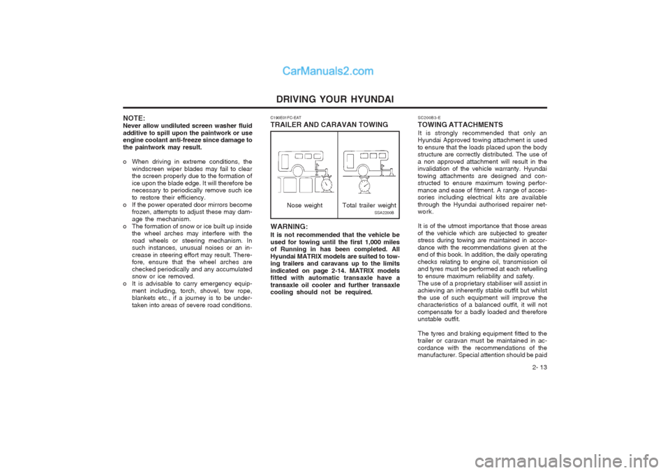
WARNING: It is not recommended that the vehicle be used for towing until the first 1,000 miles of Running in has been completed. All Hyundai MATRIX models are suited to tow- ing trailers and caravans up to the limits indicated on page 2-14. MATRIX models fitted with automatic transaxle have a transaxle oil cooler and further transaxle cooling should not be required.
C190E01FC-EAT TRAILER AND CARAVAN TOWING
Nose weightSSA2200B
Total trailer weight
Page 95 of 407

IN CASE OF EMERGENCY
3-8
SD070K1-E AFTER CHANGING WHEELS The pressure of the spare tyre should be checked at the first available opportunity. If any doubt exists as to the tyre pressure, the vehicle should be driven slowly to the nearest service station and the tyre pressure checked and adjusted as required. If the valve cap is lost from any of the valves, a replacement should be obtained and fitted at the first available opportunity. The valve cap prevents the ingress of dirt which may cause the valve to stick and therefore leak and is part of the valve sealing function. Ensure that the spare wheel, jack and wheel nut wrench as well tools are correctly located in the boot of the vehicle to prevent damage and noise.
D060B01FC
HFC01
D080A01O-GAT
IF YOUR VEHICLE MUST BE TOWED If your vehicle has to be towed, it should be done by your Hyundai authorised repairer or a commercial tow truck service. This will help assure that your vehicle is not damaged in towing. Also, professionals are generally aware of local laws governing towing. In any case, rather than risk damage to your car, it is suggested that you show this information to the tow truck operator. Be sure that a safety chain system is used and that all local laws are observed. It is recommended that your vehicle be towed with a wheel lift and dollies or flatbed equip- ment with all the wheels off the ground. CAUTION:
o Your vehicle can be damaged if towed incorrectly!
o Be sure the transaxle is in neutral.
o When the engine will not start, be sure the steering is unlocked by placing thekey in the "ACC" position. D080B01O-GAT
Towing the Vehicle
Your vehicle can be towed by wheel lift typetruck (1), (2) or flatbed equipment (3).
dolly
(1)
(2)
(3)
Page 97 of 407
IN CASE OF EMERGENCY
3-10 D120A01A-EAT
IF YOU LOSE YOUR KEYS Information about the key of immobiliser sys-
tem will be found on page 1-2.
NOTE: Before towing, check the level of theautomatic transaxle fluid. If it is below the "HOT" range on the dipstick, add fluid. If you cannot add fluid, a towing dolly must be used. CAUTION: If the car is being towed with all four wheels on the ground, it can be towed only from the front. Be sure that the transaxle is in neutral. Do not tow at speeds greater than 30 mph (50 km/h) and for more than 15 miles (25 km). Be sure the steering is unlocked by plac-ing the key in the "ACC" position. A driver must be in the towed vehicle to operate the steering and brakes
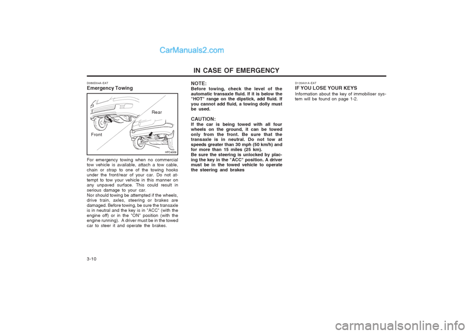
D080D04A-EAT Emergency Towing
HFC4009
Front
Rear
For emergency towing when no commercial tow vehicle is available, attach a tow cable, chain or strap to one of the towing hooks under the front/rear of your car. Do not at- tempt to tow your vehicle in this manner on any unpaved surface. This could result in serious damage to your car.Nor should towing be attempted if the wheels, drive train, axles, steering or brakes are damaged. Before towing, be sure the transaxle is in neutral and the key is in "ACC" (with the engine off) or in the "ON" position (with the engine running). A driver must be in the towed car to steer it and operate the brakes.
Page 103 of 407
VEHICLE MAINTENANCE REQUIREMENTS
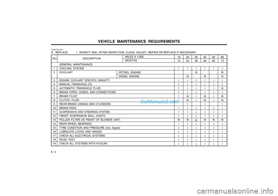
5- 4 F030C01E-EAT
R : REPLACE I : INSPECT AND, AFTER INSPECTION, CLEAN, ADJUST, REPAIR OR REPLACE IF NECESSARY
GENERAL MAINTENANCE COOLING SYSTEMCOOLANT PETROL ENGINEDIESEL ENGINE
ENGINE COOLANT SPECIFIC GRAVITYMANUAL TRANSAXLE OILAUTOMATIC TRANSAXLE FLUIDBRAKE PIPES, HOSES, AND CONNECTIONSBRAKE FLUIDCLUTCH FLUIDREAR BRAKE LININGS AND CYLINDERSBRAKE PADSSUSPENSION AND STEERING SYSTEMFRONT SUSPENSION BALL JOINTSPOLLEN FILTER (IN FRONT OF BLOWER UNIT)REAR WHEEL BEARINGSTYRE CONDITION AND PRESSURE (incl. Spare)LUBRICATE LOCKS AND HINGESCHECK ALL ELECTRICAL SYSTEMSROAD TESTCHECK ALL SYSTEMS WITH HI-SCAN
60 72
50 60
4048
I
R R
I I
R I
R R I I II
R
IIIII I
I I IIII I I I I
R I III I I
I
R IIII
R R I I I I
R I III I I
30 36
2024
I
R
I IIII I I II
R IIIIII
I
R IIII
R R I I I I
R I III I I
10 12
I I IIII I I I I
R I III I I
MILES X 1,000 MONTHS
NO. DESCRIPTION
1 2 3 456789
10111213141516171819
Page 107 of 407

VEHICLE MAINTENANCE REQUIREMENTS
5- 8 6ZF070P1-A
o Driveshafts and Boots Check the drive shafts, boots and clamps for cracks, deterioration, or damage. Replaceany damaged parts and, if necessary, repackthe grease. 6ZF070Q1-A
o Air conditioning Refrigerant Check the air conditioning lines and connec- tions for leakage and damage. Check airconditioning performance according to therelevant shop manual if necessary.
6ZF070L1-A
o Suspension Mounting Bolts Check the suspension connections for loose-
ness or damage. Retighten to the specifiedtorque. 6ZF070M1-A
o Steering Gear Box, Linkage & Boots/
Lower arm Ball Joint
With the vehicle stopped and engine off, check for excessive freeplay in the steering wheel. Check the linkage for bends or damage. Check the dust boots and ball joints for dete-rioration, cracks, or damage. Replace anydamaged parts. 6ZF070N1-A
o Power Steering Pump, Belt and Hoses Check the power steering pump and hoses for leakage and damage. Replace any dam-aged or leaking parts immediately. Inspect thepower steering belt for evidence of cuts,cracks, excessive wear, oil contaminationand proper tension. Replace or adjust it ifnecessary.
Page 126 of 407

OWNER MAINTENANCE 6-19
SG150A1-E STEERING WHEEL FREEPLAY
Steering wheel freeplay should be checked to
ensure that the specified value is not exceeded.
G150A01FC
1.18 in. (30 mm)
The clutch pedal freeplay should be checked
against the specified value. If the freeplay is not correct, the clutch should be adjusted by aHyundai authorised repairer. SG160A1-E
CLUTCH PEDAL FREEPLAY
G160A01E
0.24 ~ 0.51 in. (6 ~ 13 mm)
SG170A1-E
BRAKE PEDAL FREEPLAY
SSA6170A
0.12 ~ 0.31 in. (3 ~ 8 mm)
The brake pedal freeplay should be checked
with the engine turned off. The pedal to floor clearance should be checked with the enginerunning and a load of 490 N applied to thepedal. If either value is incorrect, the necessaryadjustment should be performed by a Hyundaiauthorised repairer. Pedal to floor clearance:1.97 in. (50 mm)
Page 142 of 407

CONSUMER INFORMATION
8-2 NOTE:
o Do not use the temporary spare tyre for tyre rotation.
o Aluminium wheels which are not sup- plied as Original Equipment should not be mixed on the same vehicle withthe original steel wheels. However, it isacceptable that the steel spare wheelbe used in conjunction with OriginalEquipment aluminium wheels since theoffset of both wheels is compatible.Radial and cross ply tyres should notbe mixed on the same vehicle.
I060A01FC-EAT
TYRE ROTATION
The tyre wear characteristics will vary be-
tween each tyre dependant upon the condi-tions of use. It is normal for the front tyres towear more rapidly than those fitted to the rearof the vehicle and therefore tyre rotation willprovide a means of helping to ensure an evenwear rate across the tyre set. For vehiclesfitted with radial ply tyres, rotation should beconfined to front to rear tyre alternation. It isnot recommended that radial ply tyres berotated from side to side. SI060A1-E
TYRE BALANCING Incorrect tyre balance will cause steering
vibration and uneven tyre wear. The vehicletyres are balanced during production but mayneed further balancing throughout the life ofthe tyres.
It is recommended that the tyres be balanced
on the car for best results and that the tyres arebalanced whenever they have been removedfrom the wheel for repair.
SI030A2-E
SNOW TYRES If it is desired to fit snow tyres to the vehicle,
it must be ascertained that the original sizeand load carrying capacity are met by thereplacement tyres. When using snow tyres,the vehicle should not be driven at speeds inexcess of 60 MPH.
SI040A1-E
TYRE CHAINS
Tyre chains, when included, should be in-
stalled on the front wheels. Be sure that thechains are the proper size and that they areinstalled in accordance with themanufacturer's instructions.
To minimise tyre and chain wear, do not
continue to use tyre chains when they are nolonger needed.
CAUTION:When driving on roads covered with snow
or ice, drive at less than 20 mph (30 km/h). Tyre pressures should be increased by 3 psi
when the vehicle is driven fully laden or underconditions of sustained high speed motoring.
HA1409Spare tyre
Page 144 of 407
VEHICLE SPECIFICATIONS 9-1
Litre
55 Imp.gal
12
SJ000A1-F
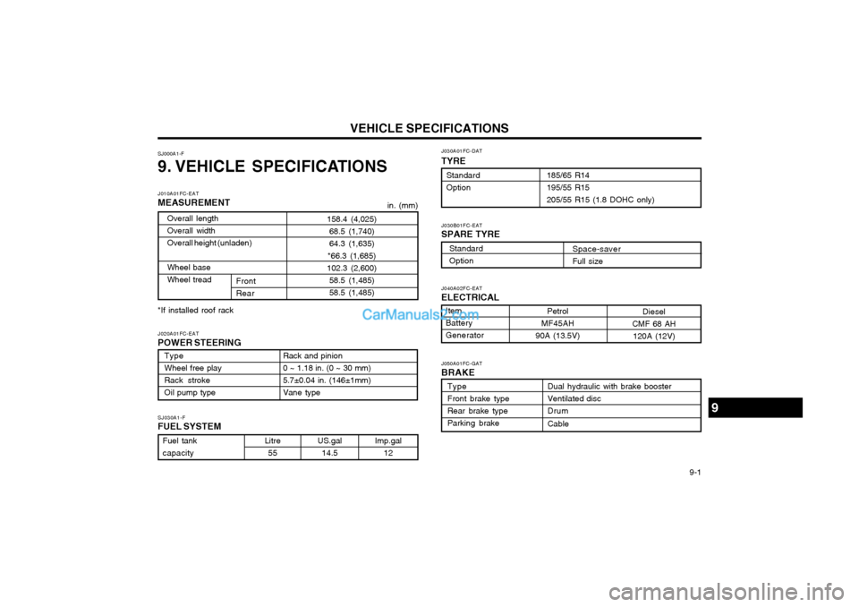
9. VEHICLE SPECIFICATIONS
Fuel tank capacity
Type Wheel free playRack strokeOil pump type
J010A01FC-EAT MEASUREMENT
in. (mm)
Item BatteryGeneratorDiesel
CMF 68 AH 120A (12V)
Petrol
MF45AH
90A (13.5V)
9
J040A02FC-EAT ELECTRICAL
SJ030A1-FFUEL SYSTEM
J020A01FC-EAT POWER STEERING
US.gal14.5
Rack and pinion 0 ~ 1.18 in. (0 ~ 30 mm)5.7±0.04 in. (146±1mm)Vane type J030A01FC-DAT
TYRE
185/65 R14 195/55 R15205/55 R15 (1.8 DOHC only)
StandardOption
Type Front brake typeRear brake typeParking brake Dual hydraulic with brake boosterVentilated discDrum Cable
J050A01FC-GAT BRAKE
Front Rear
Overall lengthOverall widthOverall height (unladen) Wheel base Wheel tread
158.4 (4,025)
68.5 (1,740)64.3 (1,635)
*66.3 (1,685)
102.3 (2,600) 58.5 (1,485)58.5 (1,485)
*If installed roof rack
Standard Option
J030B01FC-EAT SPARE TYRE Space-saver Full size
Page 150 of 407
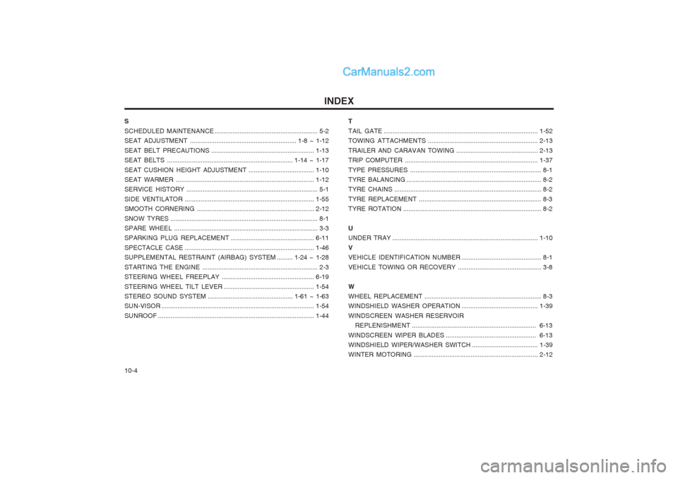
INDEX
10-4
S SCHEDULED MAINTENANCE
.......................................................... 5-2
SEAT ADJUSTMENT .. .......................................................... 1-8 ~ 1-12
SEAT BELT PRECAUTIONS .......................................................... 1-13
SEAT BELTS ....................................................................... 1-14 ~ 1-17
SEAT CUSHION HEIGHT ADJUSTMENT .....................................1-10
SEAT WARMER .............................................................................. 1-12
SERVICE HISTORY .......................................................................... 5-1
SIDE VENTILATOR ......................................................................... 1-55
SMOOTH CORNERING ............. .....................................................2-12
SNOW TYRES ................................................................................... 8-1
SPARE WHEEL ................................................................................. 3-3
SPARKING PLUG REPLACEMENT ...............................................6-11
SPECTACLE CASE ......................................................................... 1-46
SUPPLEMENTAL RESTRAINT (AIRBAG) SYSTEM ......... 1-24 ~ 1-28
STARTING THE ENGINE ................................................................. 2-3
STEERING WHEEL FREEPLAY ....................................................6-19
STEERING WHEEL TILT LEVER ...................................................1-54
STEREO SOUND SYSTEM ................................................ 1-61 ~ 1-63
SUN-VISOR ...................................................................................... 1-54
SUNROOF ........................................................................................ 1-44TTAIL GATE
....................................................................................... 1-52
TOWING ATTACHMENTS .............................................................. 2-13
TRAILER AND CARAVAN TOWING ..............................................2-13
TRIP COMPUTER ........................................................................... 1-37
TYPE PRESSURES .......................................................................... 8-1
TYRE BALANCING ............................................................................ 8-2
TYRE CHAINS ................................................................................... 8-2
TYRE REPLACEMENT ..................................................................... 8-3
TYRE ROTATION .............................................................................. 8-2
U UNDER TRAY .................................................................................. 1-10
VVEHICLE IDENTIFICATION NUMBER ............................................. 8-1
VEHICLE TOWING OR RECOVERY ............................................... 3-8
WWHEEL REPLACEMENT .................................................................. 8-3
WINDSHIELD WASHER OPERATION ...........................................1-39
WINDSCREEN WASHER RESERVOIR REPLENISHMENT ...................................................................... 6-13
WINDSCREEN WIPER BLADES ................................................... 6-13
WINDSHIELD WIPER/WASHER SWITCH .....................................1-39
WINTER MOTORING ...................................................................... 2-12