Hyundai Matrix 2006 Owner's Manual
Manufacturer: HYUNDAI, Model Year: 2006, Model line: Matrix, Model: Hyundai Matrix 2006Pages: 490, PDF Size: 11.58 MB
Page 241 of 490

6
DO-IT-YOURSELF MAINTENANCE
35
!WARNING:
o Do not smoke or have any other open flame near the vehicle while bleeding the fuel system.
o Be sure to carefully wipe away any water drained out in thismanner, because the fuel mixed in the water might be ignited and result in a fire.
HEADLIGHT AIMING ADJUSTMENT
G290A01FC-GAT Before performing aiming adjustment, make sure of the following.
1. Keep all tires inflated to the correct
pressure.
2. Place the vehicle on level ground and press the front bumper and rear bumper down several times.Place the vehicle at a distance of 3,000 mm (118 in.) from the test wall.
3. See that the vehicle is unloaded
(except for full levels of coolant,engine oil and fuel, and spare tire, jack, and tools).
4. Clean the head lights lens and turn on the headlight (low beam). G290A01FC
5. Open the hood.
6. Draw the vertical line (through the center of each headlight beam pat- tern) and the horizontal line (throughthe center of each headlight beam pattern) on the aiming screen. And then, draw a horizontal paral- lel line at 30 mm (1.18 in.) under the horizontal line.
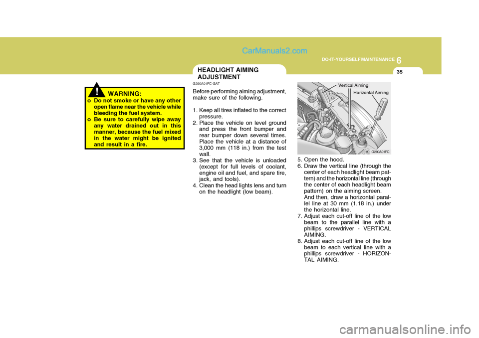
7. Adjust each cut-off line of the low beam to the parallel line with aphillips screwdriver - VERTICALAIMING.
8. Adjust each cut-off line of the low beam to each vertical line with a phillips screwdriver - HORIZON- TAL AIMING.
Horizontal Aiming
Vertical Aiming
Page 242 of 490

6 DO-IT-YOURSELF MAINTENANCE
36
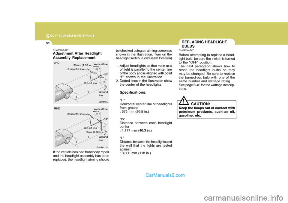
be checked using an aiming screen as shown in the illustration. Turn on theheadlight switch. (Low Beam Position)
1. Adjust headlights so that main axisof light is parallel to the center line of the body and is aligned with point"P" shown in the illustration.
2. Dotted lines in the illustration show
the center of the headlights. Specifications: "H" Horizontal center line of headlights from ground: 675 mm (26.5 in.) "W" Distance between each headlight center : 1,177 mm (46.3 in.) "L" Distance between the headlights andthe wall that the lights are testedagainst: 3,000 mm (118 in.).REPLACING HEADLIGHT BULBS
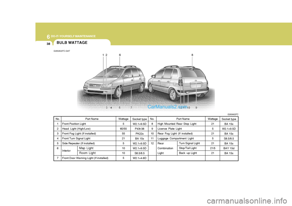
G260A03A-GAT Before attempting to replace a head- light bulb, be sure the switch is turned to the "OFF" position. The next paragraph shows how to reach the headlight bulbs so they may be changed. Be sure to replacethe burned-out bulb with one of the same number and wattage rating. See page 6-40 for the wattage descrip- tions.
CAUTION:
Keep the lamps out of contact with petroleum products, such as oil,gasoline, etc.
!
G290B02FC-GAT
Adjustment After Headlight Assembly Replacement
If the vehicle has had front body repair and the headlight assembly has beenreplaced, the headlight aiming should G290B01L
L
W
H
H Cut-off line
"P"
30mm (1.18 in.)
Vertical line
Horizontal line
Ground line
LHD
G290B01L-D
LW
H
H Cut-off line
"P"
30mm (1.18 in.) Vertical line
Horizontal line
Ground line
RHD
Page 243 of 490

6
DO-IT-YOURSELF MAINTENANCE
37
G270A02A-GAT
HEADLIGHT BULB Replacement instructions:
1. Allow the bulb to cool. Wear eye protection.
2. Always grasp the bulb by its plastic base, avoid touching the glass.
3. Disconnect the power cord from
the bulb base in the back of the headlight.
4. Remove the dust cover. G270A01FC
!
5. Push the bulb spring for removing
the headlight bulb.
6. Remove the protective cap from the replacement bulb and install the new bulb by matching the plas- tic base with the headlight hole.Install the dust cover after retight- ening the bulb spring and recon- nect the power cord.
7. Use the protective cap and carton
to dispose of the old bulb.
8. Check for proper headlight aim. G270A02FC
WARNING:
The halogen bulb contains gasunder pressure and if impacted could shatter, resulting in flying fragments. Always wear eye pro-tection when servicing the bulb. Protect the bulb against abrasions or scratches and against liquidswhen lighted. Turn on the bulb only when installed in a headlight. Replace the headlight if damagedor cracked. Keep the bulb out of the reach of children and dispose of the used bulb with care.
Page 244 of 490

6 DO-IT-YOURSELF MAINTENANCE
38
Socket type
W2.1×9.5D P43t-38
PK22s
BA 15s
W2.1×9.5D W2.1×9.5D S8.5/8.5
W2.1×4.6D Part Name
High Mounted Rear Stop Light License Plate Light Rear Fog Light (If installed) Luggage Compartment Light Rear Combination Light
No.
1 2 3 4 5 6 7
BULB WATTAGE
G280A02FC-GAT
G280A02FC
Part Name
Front Position Light Head Light (High/Low) Front Fog Light (If installed) Front Turn Signal Light Side Repeater (If installed) InteriorFront Door Warning Light (If installed) No.
8 9
1011 12
Wattage
5
60/55 55 215
10 10 5
Socket type BA 15s
W2.1×9.5D
BA 15s
S8.5/8.5
BA 15s
BAY 15d
BA 15s
Map Light Room Light
Turn Signal Light Stop/Tail Light Back -up Light
Wattage
21
5
21
5
21
21/5 21
Page 245 of 490

6
DO-IT-YOURSELF MAINTENANCE
39FUSE PANEL DESCRIPTION
G200C03FC-GAT
Engine Compartment (Gasoline Engine)
G200C03FC
NOTE: Not all fuse panel descriptions in this manual may be applicable to your vehicle. It is accurate at the time of printing. When you inspect the fuse box on your vehicle, refer to the fuse box label.
PROTECTED COMPONENTS
Generator (A/CON, RR HTD, STOP, D/LOCK, HAZARD) Fuse Generator, Engine control relay, ECM Radiator fan relay Start relay, Ignition switch Blower relay Power window relay Condenser fan relay #1 ABS control module, ABS bleeding connector, ESP ABS control module, ABS bleeding connector, ESP Fuel pump relay Injector, lgnition coil MAP sensor, Oxygen sensor, CP sensor, Knock sensor, Throttle position sensor Audio, Room lamp, Overhead console lamp, lnstrument cluster DRL control module Horn relay A/C relay Front fog lamp relay ECM, TCM Tail lamp relay Left rear combi lamp, Left position lamp, Left License lamp Right rear combi lamp, Right position lamp, Right License lamp Left head lamp Right head lamp, (H/LP IND) Fuse
FUSE RATING
120A
40A 30A 20A 40A 40A 30A 20A 40A 40A 10A 15A 10A10A 15A 10A 10A 15A 10A 20A 10A 10A 15A 15A
DESCRIPTION
ALTB+
ECU RAD IGN
BLR
P/WIN
COND
ABSABS
F/PUMP INJ
SNSR
ROOM LP DRL
HORN
A/CON
FR FOG ECU
LP
TAIL LH
TAIL RH H/LP LH
H/LP RH
Page 246 of 490

6 DO-IT-YOURSELF MAINTENANCE
40
G200E03FC
G200E03FC-GAT
(Diesel Engine)
NOTE: Not all fuse panel descriptions in this manual may be applicable to your vehicle. It is accurate at the time of printing. When you inspect the fuse box on your vehicle, refer to the fuse box label.
Page 247 of 490

6
DO-IT-YOURSELF MAINTENANCE
41
ALT B+
ECU RAD
IGN
BLR
P/WIN
COND ABSABS
F/PUMP ECU ECU
SNSR
ROOM LP DRL
HORN
A/CON
FR FOG ECU
LP
TAIL LH
TAIL RH H/LP LH
H/LP RH
PTC HTR 1
GLOW
PTC HTR 2 FFHS
PTC HTR 3 PROTECTED COMPONENTS
Generator (A/CON, RR HTD, STOP, D/LOCK, HAZARD) Fuse, Deicer Generator, Engine control relay, ECM Radiator fan relayStart relay, Ignition switchBlower relayPower window relayCondenser fan relay #1 ABS control module, ABS bleeding connector, ESP ABS control module, ABS bleeding connector, ESPFuel pump relayECM No.5 (Batt+)ECM No.4 (Batt+), Stop lamp switch, PTC heater relay #1Glow plug relay, Assistor heater relay 1/2, Stop lamp switch, TDC sensor, EGR act, Throttle plate act, VGT vacuum Audio, Room lamp, Overhead console lamp, lnstrument cluster, ETACM, Luggage lampDRL control moduleHorn relayA/C relayFront fog lamp relay ECM, TCM Tail lamp relayLeft rear combi lamp, Left position lamp, Left License lampRight rear combi lamp, Right position lamp, Right License lampLeft head lampRight head lamp, (H/LP IND) Fuse PTC heater relay #1 GLOW relayPTC heater relay #2FFHS relayPTC heater relay #3
FUSE RATING
140A40A30A30A40A40A 30A 30A40A40A10A30A 10A 15A 10A 15A10A10A 15A 10A20A10A10A15A 15A 40A80A40A30A40A
FUSE
FUSIBLE LINK DESCRIPTION
Page 248 of 490

6 DO-IT-YOURSELF MAINTENANCE
42
G200D01FC-GAT Inner Panel
G200D01FC
DESCRIPTIONH/LP IND
HTD IND
A/CON
RR HTD STOP
D/LOCK
HAZARD AUDIO
C/LIGHT A/B
A/B IND
T/SIG
ECU
ETACS
RR WPR
START
FRT WPR S/HTD
P/OUTLET
IG2
O/S MRRPROTECTED COMPONENTS
Head lamp indicator Defogger relay, Left(Right) outside mirror motor,Rear window motorA/C SwitchDefogger relayStop lamp switch, Power window relay Door lock(unlock) relay, ETACM, Sunroof relay Burglar alarm relay, Hazard relayAudioCigarette lighterSRS control moduleSRS IND. Hazard switch, Seat belt timer, Instrument cluster, ABS control module, Pre-excitation resistor, Washer motorECM, Vehicle speed sensor, TCM, Ignition coilETACM, A/T Shift leverRear wiper motor, Rear wiper relayStart relay Wiper relay, Washer motor, Wiper & Defogger timer Left (Right) front seat warmer switchFront (Rear) power outletETACM, Power window relay, Defogger relay, Sunroof relayHead lamp relay, Blower relayOutside mirror switch, Rear fog lamp relay
FUSE RATING
10A 10A 10A 30A10A15A 10A 10A15A10A10A 10A 15A 10A10A 10A 20A15A25A 10A 10A
Page 249 of 490

Emission Control System ............................................ 7-2
Catalytic Converter ...................................................... 7-3
EGR System ................................................................ 7-4
7
EMISSION CONTROL SYSTEM
7
Page 250 of 490

7EMISSION CONTROL SYSTEMS
2EMISSION CONTROL SYSTEMS
H010A01A-GAT
(If Installed)
Your Hyundai is equipped with an
emission control system to meet all requirements of the Emission prohibi- tion rules of your province.
There are three emission control sys-
tems which are as follows.
(1) Crankcase emission control sys- tem
(2) Evaporative emission control sys- tem
(3) Exhaust emission control system
In order to assure the proper function
of the emission control systems, it is recommended that you have your carinspected and maintained by an au- thorized Hyundai dealer in accordance with the maintenance schedule in thismanual. H010B01A-AAT
1. Crankcase Emission Control
System
The positive crankcase ventilation
system is employed to prevent airpollution caused by blow-by gasesbeing emitted from the crankcase. This system supplies fresh filtered air to the crankcase through the air in-take hose. Inside the crankcase, the fresh air mixes with blow-by gases, then passes through the PCV valveinto the induction system.
H010C01E-GAT
2. Evaporative Emission Control
System
The Evaporative Emission Control
System is designed to prevent fuel vapors from escaping into the atmo- sphere. Canister
While the engine is inoperative, fuel
vapors generated inside the fuel tank are absorbed and stored in the canis- ter. When the engine is running, thefuel vapors absorbed in the canister are drawn into the induction system through the purge control solenoidvalve. Purge Control Solenoid Valve (PCSV)
The purge control solenoid valve is
controlled by the Engine Control Mod- ule (ECM); when the engine coolant temperature is low during idling, the PCSV closes so that evaporated fuelis not taken into the engine. After the engine warms-up during ordinary driv- ing, the PCSV opens so as to intro-duce evaporated fuel to the engine.
H010D01A-AAT
3. Exhaust Emission Control
System
The Exhaust Emission Control Sys-
tem is a highly effective system which controls exhaust emissions while maintaining good vehicle performance.