ECO mode Hyundai Matrix 2006 Owner's Guide
[x] Cancel search | Manufacturer: HYUNDAI, Model Year: 2006, Model line: Matrix, Model: Hyundai Matrix 2006Pages: 490, PDF Size: 11.58 MB
Page 283 of 490

1
CONTROLS AND EQUIPMENT
3RUNNING IN
B020A02FC-EAT Petrol Engine The longevity and performance of the vehicle are greatly affected by the careexercised during the first 1,000 miles of motoring. Because of modern manu- facturing techniques, rigid guidelinesregarding maximum road speeds have become unnecessary. However, cer- tain precautions should be observed inorder to obtain the best possible perfor- mance and useful life from the vehicle.
1) Do not race the engine without a load (i.e revving the engine in neutral).
2) During the first 500 miles the maxi-
mum engine speed should be re- stricted to 3,000 rpm and gradually increased thereafter.
3) Avoid prolonged constant speed op- eration. The internal components willbecome run in more quickly if the operation speed is varied during therunning-in period.
4) Never allow the engine to labour. Use
the gearbox freely and avoid largethrottle open-ings when the engine speed is below 1,500 rpm. 5) Avoid rapid acceleration and maxi-
mum throttle openings.
6) Avoid harsh braking during the first 100 miles of urban motoring or 1,000 miles of motorway driving to allowthe friction facings of the brake pads and shoes to bed against the discs and drums properly.
7) No trailer towing should be under- taken during the running in period.
ZB010C1-E "Alternative fuels" Fuels which contain methanol or etha- nol must not be used. ZB010D1-E Operation in Foreign Countries Drivers of vehicles which are to be operated in foreign countries must sat- isfy themselves that:
o The vehicle meets all local regula-
tions with respect to insurance, speci- fications etc..
o The correct types and grades of fuel are available for satisfactory opera-tion of the vehicle.
ZB010F2-A Fuels for Cleaner Air To help contribute to cleaner air, Hyundai recommends that you use fuels treatedwith detergent additives, which help to prevent deposit formation in the engine. These fuels will help the engines runcleaner and the Emission Control Sys- tem performance.
Page 284 of 490

1CONTROLS AND EQUIPMENT
4IMMOBILISER SYSTEM
B020B02FC-EAT Diesel Engine The longevity and performance of the vehicle are greatly affected by the care exercised during the first 1,000 miles ofmotoring. Because of modern manu- facturing techniques, rigid guidelines regarding maximum road speeds havebecome unnecessary. However, cer- tain precautions should be observed in order to obtain the best possible perfor-mance and useful life from the vehicle.
1) Do not race the engine without a load (i.e revving the engine in neutral).
2) During the first 600 miles the maxi- mum engine speed should be re- stricted to 3,000 rpm and graduallyincreased thereafter. And whilst driv- ing, keep under three quarters of maximum vehicle speed.
3) Avoid prolonged constant speed op- eration. The internal components ofthe engine will become run in morequickly if the operation speed is var- ied during the running in period.
4) Never allow the engine to labour. Use the gearbox freely and avoid largethrottle open-ings when the engine speed is below 1,500 rpm. 5) Avoid rapid acceleration and maxi-
mum throttle openings.
6) Avoid harsh braking during the first 100 miles of urban motoring or 1,000miles of motorway driving to allowthe friction facings of the brake pads and shoes to bed against the discs and drums properly.
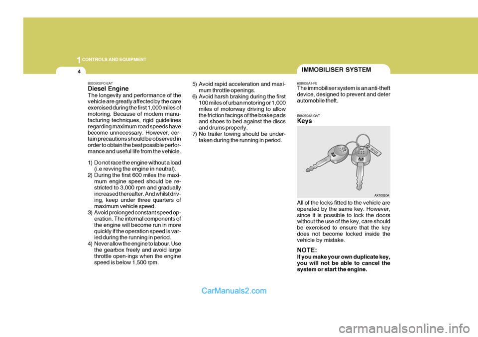
7) No trailer towing should be under- taken during the running in period. B880B03A-GAT Keys
6SB035A1-FE The immobiliser system is an anti-theft device, designed to prevent and deterautomobile theft. All of the locks fitted to the vehicle are operated by the same key. However,since it is possible to lock the doors without the use of the key, care should be exercised to ensure that the keydoes not become locked inside the vehicle by mistake. NOTE: If you make your own duplicate key, you will not be able to cancel the system or start the engine. AX10020A
Page 285 of 490

1
CONTROLS AND EQUIPMENT
5
B880C02A-GAT Key Numbers The vehicle key number is recorded upon a metal tag attached to the keys when the vehicle is first delivered to you.The key number should be recorded and kept in a safe place in case the need to order further keys arises. Newkeys are available from any Hyundai authorised repairer by quoting the rel- evant key number. In the interest of security, the metal tagattached to the keys which bears thekey number should be removed from the key ring after you receive your new vehicle. In addition, key numbers can-not be provided by Hyundai for security reasons. If you need additional keys or if youshould lose your keys, your Hyundai authorised repairer can make new keys.
AX10030A
!
DOOR
B040A02Y-EAT DOOR LOCKS
WARNING:
o Unlocked doors can be danger- ous. Before you drive away (espe- cially if there are children in the car), be sure that all the doors aresecurely closed and locked so that the doors cannot be inadvertently opened from the inside. This helpsensure that doors will not be opened accidentally. Also, when combined with the proper use ofseat belts, locking the doors helps keep occupants from being ejected from the car in case of an accident.
o Before opening the door, always look for and avoid oncoming traf-fic.
o In case of accident the door is unlocked automatically (Not allmodels)
Page 287 of 490

1
CONTROLS AND EQUIPMENT
7
SB040D1-F Locking From The Inside To lock the doors from inside, simply close the door and push the lock switch to the "LOCK" position. When this is done, the door cannot beusing either the inside or the outside door handle. NOTE: When the door is locked, the red mark on the switch is not visible and the character "LOCK" on the switch is visible. SB040F2-E Child-proof Rear Door Lock The rear doors are fitted with child proof locks to prevent accidental opening of the doors using the inside door handle, whilst allowing access by means of theoutside handle (such as is required in the event of an acccident for example) provided that the door lock button is atthe unlocked position. Use of the child proof lock mechanism is recommended when children are carried in the vehicle.The child proof lock mechanism may be activated by opening the door and moving the lever located by the doorlatch to the " " position. Move the lever to the " " position when normal door operation is desired.SB040G1-F Central Door Lock (Not all models) The central door locking is operated by pushing the driver's door lock switch toward the front or rear of the vehicle. If the passenger and rear doors are openwhen the switch is pushed, the door will remain locked when closed. NOTE:
o When pushing the switch toward
the rear, all doors and tail gate will unlock. When pushing the switch towardthe front, all doors and tail gate will lock.
HFC2005-D
LOCK
UNLOCK
HFC2006-D
B040G01FC-D
Page 288 of 490

1CONTROLS AND EQUIPMENT
8ANTI-THEFT ALARM SYSTEM
B070B01O-DAT Armed Stage Park the car and stop the engine. Arm the system as described below.
1) Remove the ignition key from theignition switch.
2) Make sure that the engine bonnet
and tail gate are closed.
3) Lock the doors using the transmitter of the keyless entry system.
After completion of the steps above, the turn signal lights will blink once to indicate that the system is armed.
o When the door is unlocked, the
red mark on the switch is visible and the character "LOCK" on the switch is visible.
o The central door locking is oper-
ated by turning the key (with theft-alarm system: driver's door and passenger's door, without theft-alarm system: driver's door only) toward the front or rear of the vehicle.
B040H02L-EAT Speed Sensing Auto Door Locking (Not all models) When the speed of the vehicle keeps above 40KM/H for 2-3 seconds, it will automatically lock all doors for driverand passenger's safety. But, the ignition key is removed, it will automatically unlock all doors. B070A01A-EAT (Not all models) This system is designed to provide protection from unauthorised entry intothe car. This system is operated in three stages: the first is the "Armed" stage, the second is the "Alarm" stage,and the third is the "Disarmed" stage. If triggered, the system provides an au- dible alarm with blinking of the turnsignal lights.
B070B01FC-D
UNLOCK
LOCK
Page 290 of 490

1CONTROLS AND EQUIPMENT
10
B070F01A-EAT Keyless Entry System (Not all models) Locking doors
1. Close all doors.
2. Push the "LOCK" button on the trans-mitter.
3. At the same time all doors lock, the
turn signal light will blink once toindicate that the system is armed.
Unlocking doors
1. Push the "UNLOCK" button on the transmitter.
2. At the same time all doors unlock,
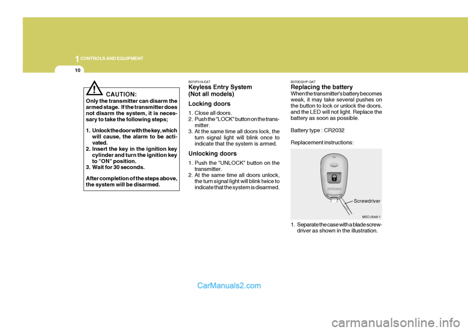
the turn signal light will blink twice to indicate that the system is disarmed. B070E02HP-GAT Replacing the battery When the transmitter's battery becomes weak, it may take several pushes on the button to lock or unlock the doors,and the LED will not light. Replace the battery as soon as possible. Battery type : CR2032 Replacement instructions:
1. Separate the case with a blade screw-
driver as shown in the illustration.
MSO-0048-1
Screwdriver
CAUTION:
Only the transmitter can disarm the armed stage. If the transmitter does not disarm the system, it is neces- sary to take the following steps;
1. Unlock the door with the key, which will cause, the alarm to be acti- vated.
2. Insert the key in the ignition key
cylinder and turn the ignition keyto "ON" position.
3. Wait for 30 seconds. After completion of the steps above, the system will be disarmed.
!
Page 291 of 490

1
CONTROLS AND EQUIPMENT
11
!
2. Remove the old battery from the
case and note the polarity. Make sure the polarity of the new battery is the same(+side facing down), then insert it in the transmitter.
MSO-0048-2
Battery
Case
WINDOW
SB060A1-E DOOR WINDOWS The front door windows may be opened or closed by turning the window regula- tor handle. Ensure that when the win- dows are closed, nothing may becometrapped between the glass and the door frame.
WARNING:
When opening or closing the win- dows, make sure your passenger's arms and hands are safety out of the way. B060A02E-EAT POWER WINDOWS (Not all models) The power windows operate when the ignition key is in the "ON" position. The
main switches are located on the driver's armrest and control the front and rearwindows on both sides of the vehicle. The windows may be opened by de- pressing the appropriate window switchand closed by pulling up the switch. To open the window on the driver's side, press the switch(1) down. The windowmoves as long as the switch is oper- ated.
B050A01FC-D
Close
B060A01FC-D
(1)
Open
Page 294 of 490

1CONTROLS AND EQUIPMENT
14
!WARNING:
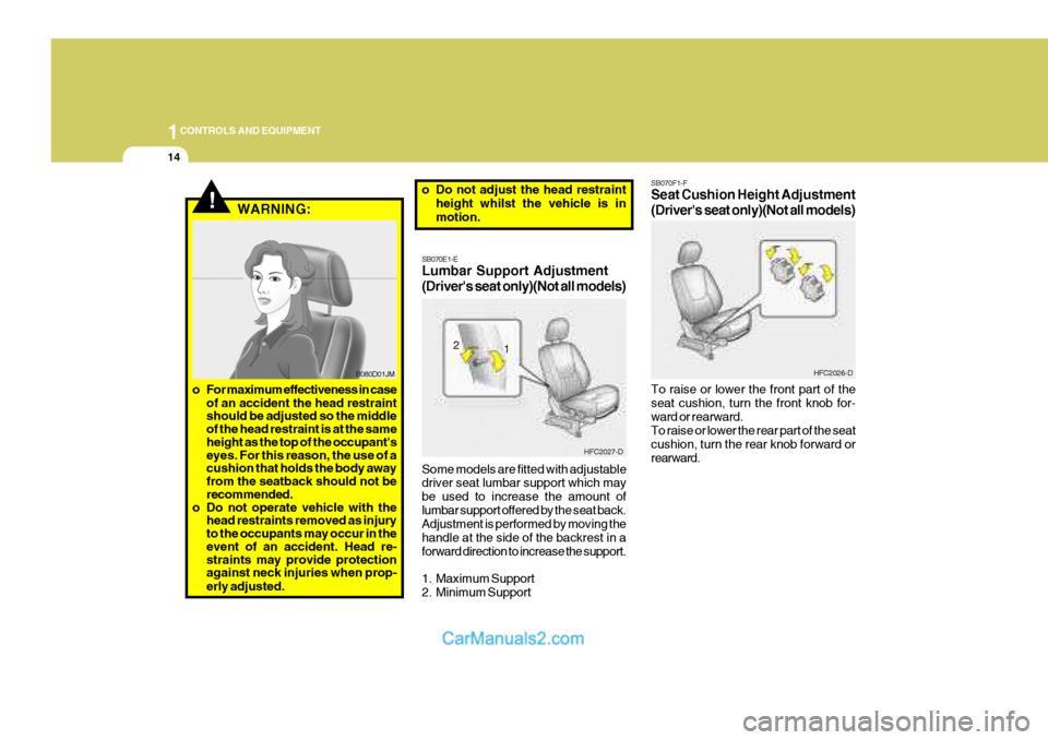
SB070E1-E Lumbar Support Adjustment (Driver's seat only)(Not all models) Some models are fitted with adjustable driver seat lumbar support which may be used to increase the amount oflumbar support offered by the seat back. Adjustment is performed by moving the handle at the side of the backrest in a
forward direction to increase the support.
1. Maximum Support
2. Minimum Support SB070F1-F Seat Cushion Height Adjustment (Driver's seat only)(Not all models) To raise or lower the front part of the seat cushion, turn the front knob for-ward or rearward. To raise or lower the rear part of the seat cushion, turn the rear knob forward orrearward.
B080D01JM
o For maximum effectiveness in case of an accident the head restraint should be adjusted so the middle of the head restraint is at the same height as the top of the occupant's eyes. For this reason, the use of a cushion that holds the body away from the seatback should not be recommended.
o Do not operate vehicle with the head restraints removed as injury to the occupants may occur in the event of an accident. Head re- straints may provide protection against neck injuries when prop- erly adjusted. o Do not adjust the head restraint
height whilst the vehicle is in motion.
1
2
HFC2027-D
HFC2026-D
Page 300 of 490

1CONTROLS AND EQUIPMENT
20
SB090H1-E CARE OF SEAT BELTS Seat belt assemblies must never be disassembled or modified in any way. In addition, care should be exercised toensure that the belt assemblies do not become damaged by being trapped in seat mechanisms, door shuts etc. SB090I-E Periodic Inspection It is recommended that all seat belts be inspected periodically for wear or dam- age of any kind. Parts of the systemthat are damaged should be replaced as soon as possible. Under no circum- stances must any part of the seat beltassemblies be dismantled or repaired.
SB090J1-E Keep Belts Clean and Dry Seat belts should be kept clean and dry. If belts become dirty, they can be cleaned using a mild soap solution and warm water. Bleach, dye, strong deter-gents or abrasives should not be used since the fabric may become damaged and weakened. SB090K1-E Replacement of Seat Belts The entire seat belt assembly or as- semblies should be replaced if the ve- hicle has been involved in an accidenteven if no damage is evident. Addi- tional questions concerning seat belt operation should be directed to a Hyundaiauthorised repairer.
B170A04A-EAT HEIGHT ADJUSTABLE FRONT SEAT SHOULDER BELT (Not all models) You can adjust the height of the shoul- der belt anchor to one of 4 positions.
B170A01E-D
SB090F1-E Seat Belt Occupancy The seat belts are designed to be used by one seat occupant only. The use ofa seat belt by more than one person increases the levels of injury which may be sustained in the event of anaccident. SB090E1-E Injured Persons A seat belt should be used when an injured person is being transported. For specific recommendations, the adviceof a qualified Medical Practioner should be sought.
SE090G1-E Do Not Lie Down To ensure that the maximum level of protection may be afforded by the seatbelt system, all passengers should be sitting in an upright position throughout the journey. The seat belt will be unableto afford maximum protection if the front seats are at or near the fully reclined position.
Page 324 of 490

1CONTROLS AND EQUIPMENT
44WARNING AND INDICATOR LIGHTS
SB210C1-FSRS (Airbag) Service Reminder Indicator Light
The SRS service reminder indicator (SRI) comes on and flashes for about 6seconds after the ignition key is turned to the "ON" position or after the engine is started, after which it will go out. This light also comes on when the SRS is not working properly.If the SRI does not come on, or continu- ously remains on after flashing for about 6 seconds when you turned the ignitionkey to the "ON" position or started the engine, or if it comes on whilst driving, have the SRS inspected by an Hyundaiauthorised repairer.
B260U01TB-EAT Immobiliser Indicator Light
This indicator light comes on for some seconds after the ignition key is turnedto the "ON" position. At this time, you can start the engine. The light goes out after the engine is running. In case thislight goes out before you start the en- gine, you must turn to the "LOCK" position and restart the engine. In casethis light blinks for five seconds when the ignition key is turned to "ON" posi- tion, this indicates that the immobilisersystem is out of order.
SB210G1-E Turn Signal Indicator Light
Operation of a turn signal is indicated by the warning light located in the in-strument cluster. If the light fails to illuminate or does not flash, a malfunc- tion within the turn signal system isindicated.
B260C02E-EATTraction Control Indicator Light(Not all models)
The traction control indicator changes operation according to the ignition switch position and whether or not the system is in operation.
B265C01LZ-EAT Electronic Stability Program Indicator Lights(Not all models)
The electronic stability program indica- tors change operation according to theignition switch position and whether the system is in operation or not. They will illuminate when the ignitionkey is turned to the "ON" position, but should go out after three seconds. If the ESP or ESP-OFF indicator stays on,take your car to your Hyundai authorised repairer and have the system checked. See section 2 for more informationabout the ESP.
It will also illuminate when the ignition key is turned to the "ON" position, andthen go off in a few seconds. If the TCS indicator stays on, take your car to your Hyundai authorised repairer and havethe system checked. See section 2 for more information about the TCS sys- tem.