clock Hyundai Matrix 2006 Owner's Guide
[x] Cancel search | Manufacturer: HYUNDAI, Model Year: 2006, Model line: Matrix, Model: Hyundai Matrix 2006Pages: 490, PDF Size: 11.58 MB
Page 218 of 490
6 DO-IT-YOURSELF MAINTENANCE
12
!
!
CHECKING AND CHANGING THE ENGINE COOLANT
G050A01A-AAT
WARNING:
Do not remove the radiator cap
when the engine is hot. When the engine is hot, the engine coolant is under pressure and may eruptthrough the opening if the cap is removed. You could be seriously burned if you do not observe thisprecaution. Do not remove the radiator cap until the radiator is cool to the touch.
10. Start the engine and check to be
sure no oil is leaking from thedrain plug or oil filter.
11.Shut off the engine and recheck
the oil level.
NOTE:
o It is recommended that the en- gine oil and filter should be changed by an authorized Hyundai dealer.
o Always dispose of used engine oil in an environmentally accept-able manner. It is suggested that it be placed in a sealed container and taken to a service station formaybe reclaimation. Do not pour the oil on the ground or put it into the household trash.
WARNING:
Used motor oil may cause irrita- tion or cancer of the skin if left in contact with the skin for prolongedperiods of time. Wash your hands thoroughly with soap and warm water as soon as possible afterhandling used oil.
8. After mounting a new centerpipe O-
ring, new oil filter element and newO-ring to upper cap, install the up- per cap to oil filter housing and retighten by turning it clockwise.Do not over-tighten. Tightening torque : 2.5 kgf.m
CAUTION:
Don't use old oil filter upper cap O-ring and centerpipe O-ring
9. Refill the crankcase with the rec- ommended engine oil. Refer to the specification in chapter 9 for engine oil capacity.
CAUTION:
Slowly pour the recommended oilby into a funnel. Do not overfill not to damage the engine.
!
!
Page 220 of 490
6 DO-IT-YOURSELF MAINTENANCE
14
G050D01FC
G050D03A-AAT
To Change the Coolant
The coolant should be changed at those intervals specified in the ve- hicle maintenance schedule in Sec- tion 5.
! CAUTION:
Engine coolant can damage the finish of your car. If you spill en-gine coolant on the car, wash it off thoroughly with clean water.
1. Park the car on level ground, set the parking brake and remove the radia- tor cap when cool.
2. Be sure your drain receptacle is in
place. Open the drain cock on theradiator. Allow all the engine cool- ant to drain from the cooling sys- tem, then securely close the draincock.
3. Check Section 9 for the capacity of the cooling system in your car.Then, following the manufacturer's directions on the engine coolant container, add the appropriatequantity of coolant to the radiator.
!
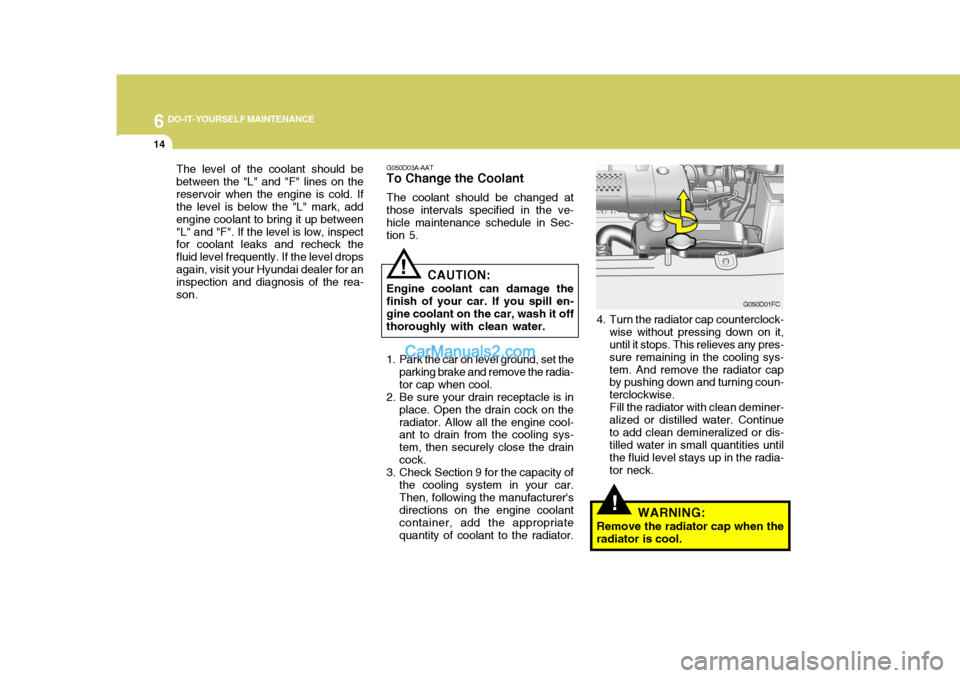
4. Turn the radiator cap counterclock-wise without pressing down on it, until it stops. This relieves any pres- sure remaining in the cooling sys-tem. And remove the radiator cap by pushing down and turning coun- terclockwise.Fill the radiator with clean deminer-alized or distilled water. Continueto add clean demineralized or dis- tilled water in small quantities until the fluid level stays up in the radia-tor neck.
WARNING:
Remove the radiator cap when theradiator is cool.
The level of the coolant should bebetween the "L" and "F" lines on thereservoir when the engine is cold. If the level is below the "L" mark, add engine coolant to bring it up between"L" and "F". If the level is low, inspect for coolant leaks and recheck the fluid level frequently. If the level dropsagain, visit your Hyundai dealer for an inspection and diagnosis of the rea- son.
Page 266 of 490
10
INDEX
3
D Defrosting/Defogging .................................................. 1-88
Digital Clock .............................................................. 1-65
Door Central door lock ...................................................... 1-9
Child-protector rear door lock .................................... 1-9
Door locks ................................................................ 1-7
Locking and unlocking front doors with a key .......... 1-7
Drink Holder ............................................................... 1-67
Drive Belts ................................................................. 6-29
Driving
Economical driving ................................................. 2-18
Smooth corneri ng .................................................... 2-19
Winter driving .......................................................... 2-20
E
EGR System ............................................................... 7-4 Electronic Stability Program (ESP) ...........................2-16
Emissions Control Systems ........................................ 7-2Engine Before starting the engine ........................................ 2-3Compartment .................................................. 6-2 ~ 6-4
Coolant ................................................................... 6-12
Coolant temperature gauge .....................................1-54
If the engine overheats ............................................. 3-4
Number ..................................................................... 8-2
Oil ............................................................................. 6-6Starting ..................................................................... 2-5
Engine Exhaust Can Be Dangerous ............................ 2-2 FFog Light
Front fog light switch .............................................. 1-63
Rear fog light switch ............................................... 1-64
Fold-up Tray .............................................................. 1-76
Front Seats Adjustable front seats ............................................. 1-14
Lumbar support control ........................................... 1-16
Seat cushion height adjustment ............................. 1-16
Fuel Capacity ................................................................... 9-2
Gauge ..................................................................... 1-54
Recommendations .................................................... 1-2
Fuel Filler Lid Remote release ...................................................... 1-77
Fuse Panel Description ............................................. 6-41
Fuses ........................................................................ 6-31
GGeneral Checks ........................................................... 6-5
Glove box .................................................................. 1-73
HHazard Warning System ............................................ 1-62
Headlight Aiming Adjustm ent .................................... 6-37
Headlight Bulb ........................................................... 6-38
Headlight Leveling Device S ystem ............................1-64
Heating and Cooling Control ......................................1-83
Page 317 of 490

1
CONTROLS AND EQUIPMENT
37
!
B990B04Y-EAT Side Impact Airbag Your Hyundai is equipped with a side impact airbag in each front seat. The purpose of the airbag is to provide the vehicle's driver and/or the front passen-ger with additional protection than that offered by the seat belt alone. The side impact airbags are designed to deployonly during certain side impact colli- sions, depending on the crash severity, angle, speed and point of impact. Theair bags are not designed to deploy in all side impact situations. B990B02Y-R
WARNING:
o The side impact airbag is supple- mental to the driver's and the passenger's three point seat belt systems and is not a substitute for them. Therefore your seat beltsmust be worn at all times whilst the vehicle is in motion. The airbags deploy only in certain sideimpact conditions severe enough to cause significant injury to the vehicle occupants. o For best protection from the side
airbag system and to avoid beinginjured is by the deploying sideimpact airbag, both front seat oc- cupants should sit in an upright position with the seat belt proper-ly fastened. The driver's hands should be placed on the steering wheel at the 9:00 and 3:00 o'clockpositions. The passenger's arms and hands should be placed in their laps.
o Do not use any accessory seat covers.
o Use of seat covers could reduce or prevent the effectiveness of thesystem.
o Do not install any accessories on the side or near the side impactairbag.
o Do not use excessive force on the side of the seat.
o Do not place any objects over the airbag or between the airbag and yourself.
HFC2092-D
Side airbag sensor
Page 321 of 490

1
CONTROLS AND EQUIPMENT
41
1. Temperature Gauge
2. Tachometer
3. Speedometer
4. Digital Clock
5. Odometer/Trip Odometer/Trip Computer (Not all models)
6. Fuel Gauge
7. Turn Signal Indicator Light
8. Automatic Transaxle Position Indicator Light (Auto T/A only)
9. Immobiliser Warning Indicator Light
10. SRS (Airbag) Warning Light
11. Electronic Stability Program (ESP) Indicator Light (Not all models)/Traction Control Indicator Light (Not all models) 12. Overdrive off Indicator Light (Not all models)
13. Parking Brake/Low Brake Fluid Level Warning Light
14. Charging System Warning Light
15. Low Fuel Warning Light
16. High Beam Indicator Light
17. Tail Gate Open Warning Light
18. Door Ajar Warning Light
19. Oil Pressure Warning Light
20. Malfunction Indicator Light (MIL)
21. ABS Warning Light (Not all models)
Page 323 of 490

1
CONTROLS AND EQUIPMENT
43
1. Temperature Gauge
2. Tachometer
3. Speedometer
4. Digital Clock
5. Odometer/Trip Odometer/Trip Computer (Not all models)
6. Fuel Gauge
7. Fuel Filter Warning Light
8. Turn Signal Indicator Light
9. Immobiliser Warning Indicator Light
10. SRS (Airbag) Warning Light
11. Diesel Pre-heat Indicator Light
12. Electronic Stability Program (ESP) Indicator Light (Not all models)/Traction Control Indicator Light (Not all models) 13. Parking Brake/Low Brake Fluid Level Warning Light
14. Charging System Warning Light
15. Low Fuel Warning Light
16. High Beam Indicator Light
17. Tail Gate Open Warning Light
18. Door Ajar Warning Light
19. Oil Pressure Warning Light
20. Malfunction Indicator Light (MIL)
21. ABS Warning Light (Not all models)
Page 339 of 490
1
CONTROLS AND EQUIPMENT
59
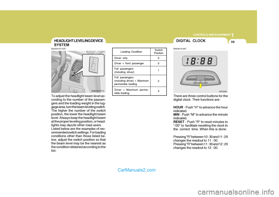
B340G01FC-EAT To adjust the headlight beam level ac- cording to the number of the passen- gers and the loading weight in the lug- gage area, turn the beam leveling switch.The higher the number of the switch position, the lower the headlight beam level. Always keep the headlight beamat the proper leveling position, or head- lights may dazzle other road users. Listed below are the examples of rec-ommended switch settings. For loading conditions other than those listed be- low, adjust the switch position so thatthe beam level may be the nearest as the condition obtained according to the list.
HEADLIGHT LEVELING DEVICE
SYSTEM
Switch
PositionLoading Condition
Driver only Driver + front passengerFull passengers (including driver) Full passengers (including driver) + Maximum
permissible loading
Driver + Maximum permis-
sible loading 0 0 1 2 3
B340G01FC-D
DIGITAL CLOCK
HFC2091
B400A01A-AAT There are three control buttons for the digital clock. Their functions are: HOUR
- Push "H" to advance the hour
indicated. MIN - Push "M" to advance the minute
indicated. RESET - Push "R" to reset minutes to
":00" to facilitate resetting the clock tothe correct time. When this is done: Pressing "R" between 10 : 30 and 11 : 29 changes the readout to 11 : 00.Pressing "R" between 11 : 30 and 12 : 29 changes the readout to 12 : 00.
Page 345 of 490
1
CONTROLS AND EQUIPMENT
65
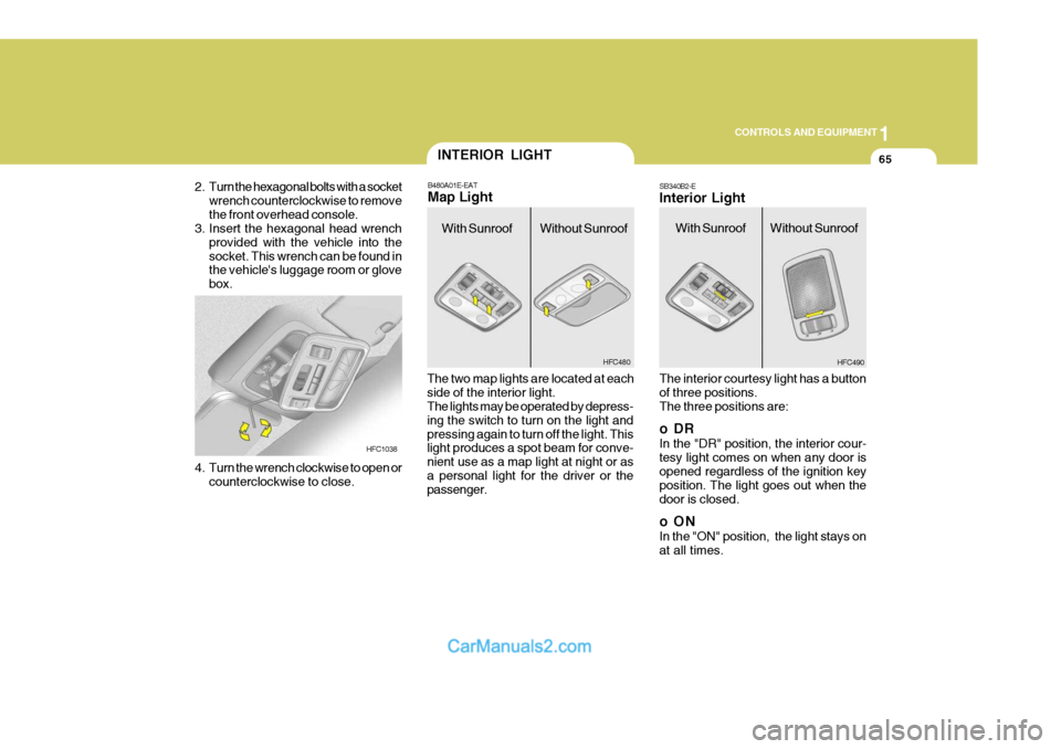
SB340B2-E Interior Light The interior courtesy light has a button of three positions. The three positions are:
oDR In the "DR" position, the interior cour- tesy light comes on when any door is opened regardless of the ignition key position. The light goes out when thedoor is closed.
oON In the "ON" position, the light stays on at all times.
2. Turn the hexagonal bolts with a socket
wrench counterclockwise to removethe front overhead console.
3. Insert the hexagonal head wrench
provided with the vehicle into thesocket. This wrench can be found in the vehicle's luggage room or glove box.
HFC1038
4. Turn the wrench clockwise to open or counterclockwise to close. B480A01E-EAT Map Light
INTERIOR LIGHT
The two map lights are located at each side of the interior light. The lights may be operated by depress- ing the switch to turn on the light andpressing again to turn off the light. This light produces a spot beam for conve- nient use as a map light at night or asa personal light for the driver or the passenger.
HFC490
With Sunroof Without SunroofWith Sunroof HFC480
Without Sunroof
Page 366 of 490

1CONTROLS AND EQUIPMENT
86
B970C01NF-EAT Automatic Operation The FATC (Full Automatic Tempera- ture Control) system automatically con- trols the heating and cooling by doing as follows:
1. Push the "AUTO" switch. The indi-
cator light will illuminate confirming that the Face, Floor and/or Bi-Level modes as well as the blower speed and air conditioner will be controlledautomatically. 2. Turn the "TEMP" knob to set the
desired temperature.The temperature will increase to the maximum 90°F(32°C) by turning the knob clockwise.The temperature will decrease to the minimum 62°F(17°C) by turning the knob counterclockwise.
NOTE:
o If the battery has been discharged or disconnected, the temperature mode will reset to Centigrade de- gree. This is a normal condition andyou can adjust the temperature mode from Centigrade to Fahren- heit as follows; Press the "OFF" and "AUTO" but-ton simultaneously for 3 seconds.The display shows that the unit of temperature is adjusted to Centi- grade or Fahrenheit.(°C
��
��
� °F or °F
��
��
� °C)
HFC227 HFC229
B970C01FC-D
Photo Sensor
o Never place anything covering the photo sensor which is located inthe car on the instrument panel toensure better control of the heat- ing and cooling system.
Page 375 of 490

1
CONTROLS AND EQUIPMENT
95
!
CAUTION:
o Be sure to remove the antenna before washing the car in an auto- matic car wash or it may be dam- aged.
o Before entering a place with a low height clearance, be sure to adjustthe roof antenna low.
o When reinstalling your antenna, it is important that it is fully tight-ened to ensure proper reception.
ANTENNA
B870D01FC-GAT Roof Antenna
HFC220 Your car uses a roof antenna to receive both AM and FM broadcast signals.This antenna is a removable type. To remove the antenna, turn the antenna counterclockwise. To install the an-tenna, turn the antenna clockwise.
HFC221