engine coolant Hyundai Matrix 2006 Owner's Guide
[x] Cancel search | Manufacturer: HYUNDAI, Model Year: 2006, Model line: Matrix, Model: Hyundai Matrix 2006Pages: 490, PDF Size: 11.58 MB
Page 221 of 490
6
DO-IT-YOURSELF MAINTENANCE
15
G050D02FC
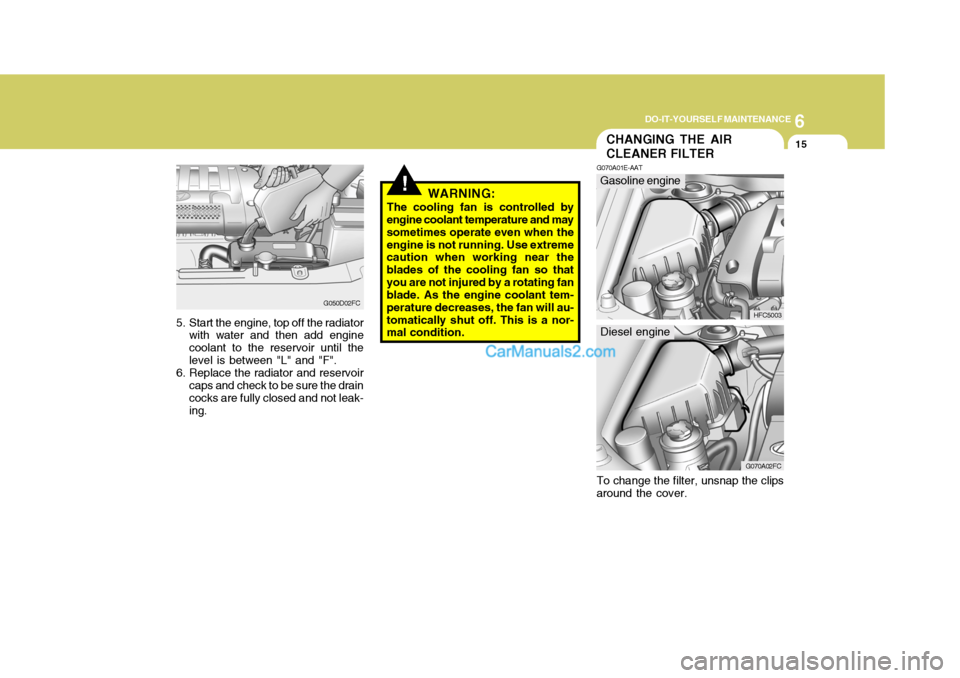
5. Start the engine, top off the radiator with water and then add engine coolant to the reservoir until the level is between "L" and "F".
6. Replace the radiator and reservoir caps and check to be sure the draincocks are fully closed and not leak- ing.
!WARNING:
The cooling fan is controlled by
engine coolant temperature and may sometimes operate even when theengine is not running. Use extreme caution when working near the blades of the cooling fan so thatyou are not injured by a rotating fan blade. As the engine coolant tem- perature decreases, the fan will au-tomatically shut off. This is a nor- mal condition.
CHANGING THE AIR CLEANER FILTER
G070A01E-AAT
HFC5003
Gasoline engine
G070A02FC
Diesel engine
To change the filter, unsnap the clips around the cover.
Page 227 of 490
6
DO-IT-YOURSELF MAINTENANCE
21
!
!
CHECKING THE BRAKES
G120A01A-AAT
! CAUTION:
Because brakes are essential to the safe operation of the car, it issuggested that they be checked and inspected by your Hyundai dealer. The brakes should bechecked and inspected for wear at those intervals specified in the vehicle maintenance schedule inSection 5.
WARNING (Diesel only):
Never work on injection system
with engine running or within 30 seconds after shutting off engine. High pressure pump, rail, injec-tors and high pressure pipes are subject to high pressure even af- ter the engine stopped. The fuel jetproduced by fuel leaks may cause serious injury, if it touch the body. People using pacemakers shouldnot move than 30cm closer to the ECU or wiring harness within the engine room while engine is run-ning, since the high currents in the Common Rail system produce considerable magnetic fields.
WARNING:
The cooling fan is controlled byengine coolant temperature andmay sometimes operate even when the engine is not running. Use extreme caution when workingnear the blades of the cooling fan so that you are not injured by a rotating fan blade. As the enginecoolant temperature decreases, the fan will automatically shut off. This is a normal condition.Fluid level should be within this range
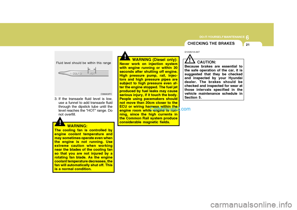
3. If the transaxle fluid level is low, use a funnel to add transaxle fluid through the dipstick tube until the level reaches the "HOT" range. Do not overfill. C090A03FC
Page 238 of 490
6 DO-IT-YOURSELF MAINTENANCE
32
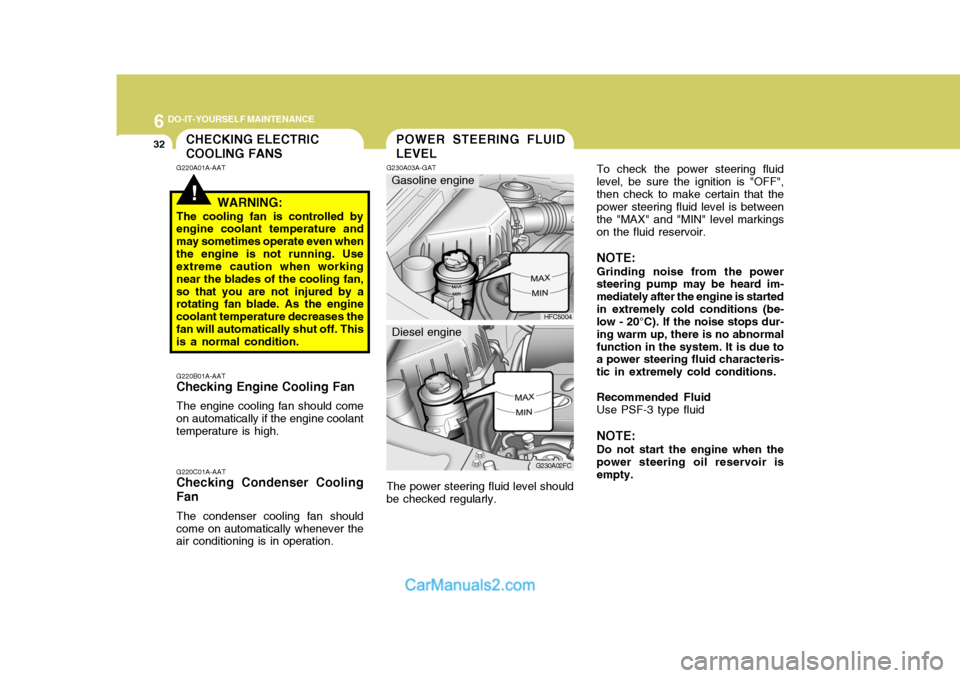
To check the power steering fluid level, be sure the ignition is "OFF",then check to make certain that the power steering fluid level is between the "MAX" and "MIN" level markingson the fluid reservoir. NOTE: Grinding noise from the power steering pump may be heard im- mediately after the engine is startedin extremely cold conditions (be- low - 20°C). If the noise stops dur- ing warm up, there is no abnormalfunction in the system. It is due to a power steering fluid characteris- tic in extremely cold conditions. Recommended Fluid Use PSF-3 type fluid NOTE: Do not start the engine when the power steering oil reservoir is empty.
!
CHECKING ELECTRIC COOLING FANS
G220A01A-AAT
WARNING:
The cooling fan is controlled by engine coolant temperature and may sometimes operate even whenthe engine is not running. Use extreme caution when working near the blades of the cooling fan,so that you are not injured by a rotating fan blade. As the engine coolant temperature decreases thefan will automatically shut off. This is a normal condition.POWER STEERING FLUID LEVEL
G220B01A-AAT
Checking Engine Cooling Fan
The engine cooling fan should come on automatically if the engine coolant temperature is high. G220C01A-AAT
Checking Condenser Cooling Fan
The condenser cooling fan should come on automatically whenever the air conditioning is in operation. G230A03A-GAT
HFC5004
G230A02FC
Gasoline engine
Diesel engine
The power steering fluid level should be checked regularly.
Page 241 of 490
6
DO-IT-YOURSELF MAINTENANCE
35
!WARNING:
o Do not smoke or have any other open flame near the vehicle while bleeding the fuel system.
o Be sure to carefully wipe away any water drained out in thismanner, because the fuel mixed in the water might be ignited and result in a fire.
HEADLIGHT AIMING ADJUSTMENT
G290A01FC-GAT Before performing aiming adjustment, make sure of the following.
1. Keep all tires inflated to the correct
pressure.
2. Place the vehicle on level ground and press the front bumper and rear bumper down several times.Place the vehicle at a distance of 3,000 mm (118 in.) from the test wall.
3. See that the vehicle is unloaded
(except for full levels of coolant,engine oil and fuel, and spare tire, jack, and tools).
4. Clean the head lights lens and turn on the headlight (low beam). G290A01FC
5. Open the hood.
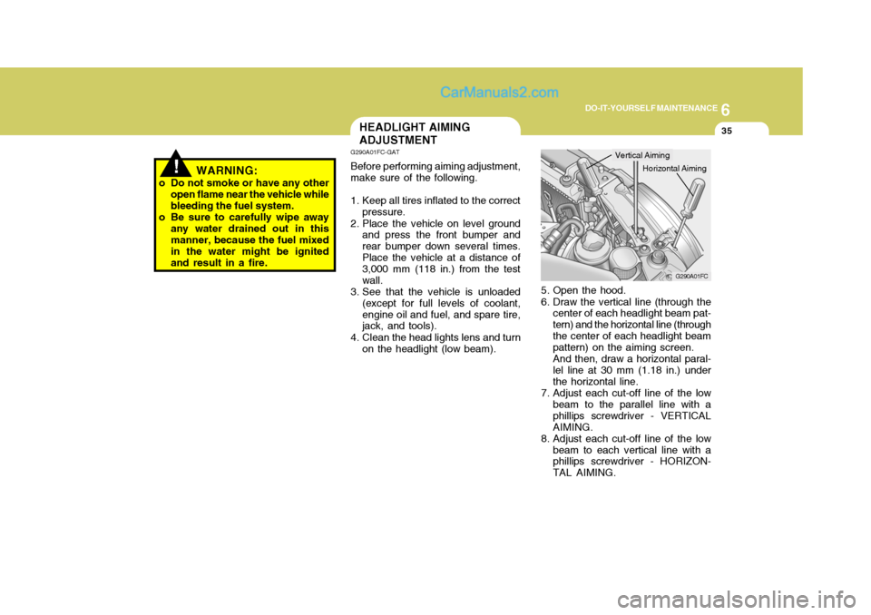
6. Draw the vertical line (through the center of each headlight beam pat- tern) and the horizontal line (throughthe center of each headlight beam pattern) on the aiming screen. And then, draw a horizontal paral- lel line at 30 mm (1.18 in.) under the horizontal line.
7. Adjust each cut-off line of the low beam to the parallel line with aphillips screwdriver - VERTICALAIMING.
8. Adjust each cut-off line of the low beam to each vertical line with a phillips screwdriver - HORIZON- TAL AIMING.
Horizontal Aiming
Vertical Aiming
Page 250 of 490
7EMISSION CONTROL SYSTEMS
2EMISSION CONTROL SYSTEMS
H010A01A-GAT
(If Installed)
Your Hyundai is equipped with an
emission control system to meet all requirements of the Emission prohibi- tion rules of your province.
There are three emission control sys-
tems which are as follows.
(1) Crankcase emission control sys- tem
(2) Evaporative emission control sys- tem
(3) Exhaust emission control system
In order to assure the proper function
of the emission control systems, it is recommended that you have your carinspected and maintained by an au- thorized Hyundai dealer in accordance with the maintenance schedule in thismanual. H010B01A-AAT
1. Crankcase Emission Control
System
The positive crankcase ventilation
system is employed to prevent airpollution caused by blow-by gasesbeing emitted from the crankcase. This system supplies fresh filtered air to the crankcase through the air in-take hose. Inside the crankcase, the fresh air mixes with blow-by gases, then passes through the PCV valveinto the induction system.
H010C01E-GAT
2. Evaporative Emission Control
System
The Evaporative Emission Control
System is designed to prevent fuel vapors from escaping into the atmo- sphere. Canister
While the engine is inoperative, fuel
vapors generated inside the fuel tank are absorbed and stored in the canis- ter. When the engine is running, thefuel vapors absorbed in the canister are drawn into the induction system through the purge control solenoidvalve. Purge Control Solenoid Valve (PCSV)
The purge control solenoid valve is
controlled by the Engine Control Mod- ule (ECM); when the engine coolant temperature is low during idling, the PCSV closes so that evaporated fuelis not taken into the engine. After the engine warms-up during ordinary driv- ing, the PCSV opens so as to intro-duce evaporated fuel to the engine.
H010D01A-AAT
3. Exhaust Emission Control
System
The Exhaust Emission Control Sys-
tem is a highly effective system which controls exhaust emissions while maintaining good vehicle performance.
Page 263 of 490

9 VEHICLE SPECIFICATIONS
4LUBRICATION CHART
Oil & Grease Standard
API SJ, SL SAE 5W-20, 5W-30
or ABOVE, SAE 10W-30 (ABOVE -18°C)
ILSAC GF-3 SAE 15W-40 (ABOVE -13°C)
or ABOVE SAE 20W-50 (ABOVE -7°C)
API CH-4 SAE 30 (0°C ~ 40°C)
or ABOVE, SAE 20W-40 (ABOVE -10°C)
ACEA B4 SAE 15W-40 (ABOVE -15°C)
or ABOVE SAE 10W-30 (-20°C ~ 40°C) SAE 5W-30 (-25°C ~ 40°C) SAE 0W-30 (BELOW 10°C) *1, *2
*1. Restricted to driving condition and area*2. Not recommended for sustained high speed vehicle operation Normal driving condition Severe driving condition HYUNDAI GENUINE PARTS MTF 75W/85 (API GL-4) HYUNDAI GENUINE ATF SP III, DIAMOND ATF SP III, SK ATF SP III or other brands approved by Hyundai Motor Co., PSF-3 DOT 3, DOT 4 or equivalent Ethylene glycol base for aluminum radiator Q'ty (liter)
1.6 DOHC - 3.3 (with oil filter) (3.5 us.qts., 2.9 Imp.qts)
1.8 DOHC - 4.0 (with oil filter) (4.2 us.qts., 3.5 Imp.qts)
1.5 CRDi - 5.3 (with oil filter)
(5.6 us.qts., 4.7 Imp.qts)
MAX. 1L / 1,500 Km MAX. 1L / 1,000 Km2.15 (2.3 us. qts., 1.86 Imp. qts) 2.0 (2.11 us. qts., 1.76 Imp. qts) (1.5 CRDi) 6.1 (6.4 us. qts., 5.3 Imp.qts) (1.6 DOHC)6.7 (7.0 us. qts., 5.8 Imp.qts) (1.8 DOHC) As required As requiredGasoline : 6.2(1.6 DOHC), 6.5(1.8 DOHC) Diesel : 6.3
J080A07FC-GAT
Item
Engine Oil Gasoline Diesel
Recommends Engine oil consumption Transaxle Manual Automatic
Power steering Brake fluid Coolant
Page 266 of 490
10
INDEX
3
D Defrosting/Defogging .................................................. 1-88
Digital Clock .............................................................. 1-65
Door Central door lock ...................................................... 1-9
Child-protector rear door lock .................................... 1-9
Door locks ................................................................ 1-7
Locking and unlocking front doors with a key .......... 1-7
Drink Holder ............................................................... 1-67
Drive Belts ................................................................. 6-29
Driving
Economical driving ................................................. 2-18
Smooth corneri ng .................................................... 2-19
Winter driving .......................................................... 2-20
E
EGR System ............................................................... 7-4 Electronic Stability Program (ESP) ...........................2-16
Emissions Control Systems ........................................ 7-2Engine Before starting the engine ........................................ 2-3Compartment .................................................. 6-2 ~ 6-4
Coolant ................................................................... 6-12
Coolant temperature gauge .....................................1-54
If the engine overheats ............................................. 3-4
Number ..................................................................... 8-2
Oil ............................................................................. 6-6Starting ..................................................................... 2-5
Engine Exhaust Can Be Dangerous ............................ 2-2 FFog Light
Front fog light switch .............................................. 1-63
Rear fog light switch ............................................... 1-64
Fold-up Tray .............................................................. 1-76
Front Seats Adjustable front seats ............................................. 1-14
Lumbar support control ........................................... 1-16
Seat cushion height adjustment ............................. 1-16
Fuel Capacity ................................................................... 9-2
Gauge ..................................................................... 1-54
Recommendations .................................................... 1-2
Fuel Filler Lid Remote release ...................................................... 1-77
Fuse Panel Description ............................................. 6-41
Fuses ........................................................................ 6-31
GGeneral Checks ........................................................... 6-5
Glove box .................................................................. 1-73
HHazard Warning System ............................................ 1-62
Headlight Aiming Adjustm ent .................................... 6-37
Headlight Bulb ........................................................... 6-38
Headlight Leveling Device S ystem ............................1-64
Heating and Cooling Control ......................................1-83
Page 329 of 490
1
CONTROLS AND EQUIPMENT
49
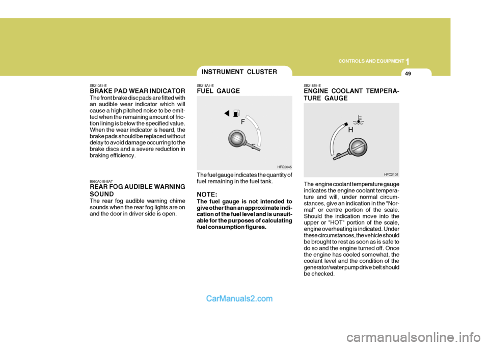
SB215B1-E ENGINE COOLANT TEMPERA- TURE GAUGE
HFC2045 HFC2101
INSTRUMENT CLUSTER
SB215A1-E FUEL GAUGE The fuel gauge indicates the quantity of fuel remaining in the fuel tank. NOTE: The fuel gauge is not intended to give other than an approximate indi- cation of the fuel level and is unsuit- able for the purposes of calculatingfuel consumption figures.
SB210S1-E BRAKE PAD WEAR INDICATOR The front brake disc pads are fitted with an audible wear indicator which will cause a high pitched noise to be emit-ted when the remaining amount of fric- tion lining is below the specified value. When the wear indicator is heard, thebrake pads should be replaced without delay to avoid damage occurring to the brake discs and a severe reduction inbraking efficiency. B950A01E-EAT REAR FOG AUDIBLE WARNING SOUND The rear fog audible warning chime sounds when the rear fog lights are onand the door in driver side is open.
The engine coolant temperature gaugeindicates the engine coolant tempera-ture and will, under normal circum- stances, give an indication in the "Nor- mal" or centre portion of the scale.Should the indication move into the
upper or "HOT" portion of the scale, engine overheating is indicated. Underthese circumstances, the vehicle should be brought to rest as soon as is safe to do so and the engine turned off. Oncethe engine has cooled somewhat, the coolant level and the condition of the generator/water pump drive belt shouldbe checked.
Page 395 of 490

2 DRIVING YOUR HYUNDAI
20
SC170E1-E Windscreen Washers and Wip- ers The windscreen washer bottle should be filled with a solution of water and aproprietary winter screen wash addi- tive. The windscreen wipers should not be used if the blades are frozen to thewindscreen or if they are covered with snow, before this is removed. NOTE: Never allow undiluted screen washer fluid additive to spill upon the paintwork or use engine coolant anti- freeze since damage to the paintworkmay result.
ZC170D1-E Door Locks Should the door lock mechanism be- come frozen, a proprietary lock de-icershould be used. Alternatively, warming the door key may thaw the door lock. However, the key should be handledcarefully to avoid burning the fingers. Never attempt to thaw a frozen door lock using hot water, since the waterwill eventually freeze and compound the problem. NOTE: The proper temperature for using the immobiliser key is from -40°F to 176°F (-40°C to 80°C). If you heat theimmobiliser key over 176°F (80°C) to open the frozen lock, it may cause damage to the transponder in itshead.
ZC170C1-E Anti-freeze/Corrosion inhibitor The cooling system must always con- tain an Ethylene-Glycol based anti-freeze solution. The system is filled during manufacture with solution of the correct strength which should bechecked before the onset of winter and adjusted or changed as required. NOTE: The anti-freeze solution contains a corrosion inhibitor to prevent degra- dation of the aluminum castingscontained within the engine. There- fore, never, drain the system and refill with water only. In addition, anti-freeze solution must ALWAYS be used in vehicles fitted withair conditioning, to prevent the heater matrix from freezing and subsequently bursting with the refrigeration system inuse.
Page 404 of 490
3 IN CASE OF EMERGENCY
4IF THE ENGINE OVERHEATS
SD040A2-E If the temperature gauge indicates over- heating:
1. Pull off the road and stop as soon as it is safe to do so.
2. Place the gear selector lever in "P" (automatic) or neutral (manual transaxle) and set the parking brake.If the air conditioning is on, turn it off.
3. If coolant is running out under the car
or steam is coming out from underthe bonnet stop the engine. Do not open the bonnet until the coolant has stopped running or the steaming hasstopped. If there is no visible loss of coolant and no steam, leave the engine running and check to be surethe engine cooling fan is operating. If the fan is not running, turn the engine off.
4. Check to see if the water pump drive belt is broken. If it is not broken,check to see that it is tight.If the drive belt seems to be satisfac- tory, check for coolant leaking from the radiator, hoses or under the car.(If the air conditioning had been in use, it is normal for cold water to be draining from it).
4. Connect the red jump cable to the
positive (+) terminal of the boosterbattery and the other end to the positive (+) terminal of the discharged battery.
5. Attach the black jump cable to the negative (-) terminal of the boosterbattery, and the other end to a groundpoint within the engine compartment of the vehicle with the flat battery. Do not connect to the negative batteryterminal of the flat battery since sparks may be generated with the subsequent risk of explosion.
6. Raise the booster vehicle engine speed to 2,000 r.p.m. and start theengine of the vehicle with the flatbattery.
7. Switch "ON" the main beam
headlamps before carefully remov-ing the jumper cables in the reverse order of attachment. Once the jumper cables have been removed, switch"OFF" the main beam headlamps. CAUTION:
If the jump cables are incorrectlyinstalled, damage to the vehicle elec- trical system may occur, in particu- lar the electronic components suchas the Fuel Injection system com- puter and the Automatic Transaxle computer. The battery must never bedisconnected whilst the engine is running.
!