Button od Hyundai Matrix 2006 Service Manual
[x] Cancel search | Manufacturer: HYUNDAI, Model Year: 2006, Model line: Matrix, Model: Hyundai Matrix 2006Pages: 490, PDF Size: 11.58 MB
Page 239 of 490
6
DO-IT-YOURSELF MAINTENANCE
33
G240A01A-AAT
POWER STEERING HOSES
It is suggested that you check the power steering hose connections for fluid leakage at regular intervals. The power steering hoses should be re-placed if there is severe surface crack- ing, scuffing or worn spots. Deteriora- tion of the hose could cause prema-ture failure.
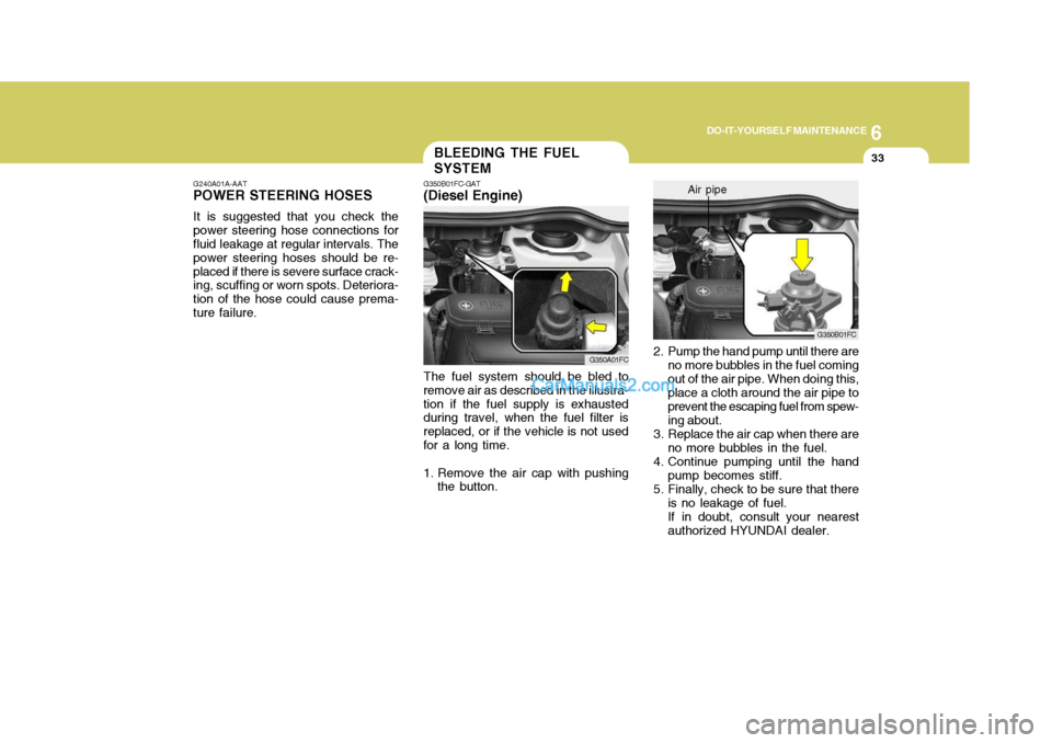
2. Pump the hand pump until there are no more bubbles in the fuel coming out of the air pipe. When doing this, place a cloth around the air pipe to prevent the escaping fuel from spew-ing about.
3. Replace the air cap when there are no more bubbles in the fuel.
4. Continue pumping until the hand pump becomes stiff.
5. Finally, check to be sure that there
is no leakage of fuel. If in doubt, consult your nearest authorized HYUNDAI dealer. G350B01FC
Air pipe
The fuel system should be bled to
remove air as described in the illustra- tion if the fuel supply is exhausted during travel, when the fuel filter is replaced, or if the vehicle is not usedfor a long time.
1. Remove the air cap with pushing the button.
G350A01FC
BLEEDING THE FUEL SYSTEM
G350B01FC-GAT
(Diesel Engine)
Page 287 of 490

1
CONTROLS AND EQUIPMENT
7
SB040D1-F Locking From The Inside To lock the doors from inside, simply close the door and push the lock switch to the "LOCK" position. When this is done, the door cannot beusing either the inside or the outside door handle. NOTE: When the door is locked, the red mark on the switch is not visible and the character "LOCK" on the switch is visible. SB040F2-E Child-proof Rear Door Lock The rear doors are fitted with child proof locks to prevent accidental opening of the doors using the inside door handle, whilst allowing access by means of theoutside handle (such as is required in the event of an acccident for example) provided that the door lock button is atthe unlocked position. Use of the child proof lock mechanism is recommended when children are carried in the vehicle.The child proof lock mechanism may be activated by opening the door and moving the lever located by the doorlatch to the " " position. Move the lever to the " " position when normal door operation is desired.SB040G1-F Central Door Lock (Not all models) The central door locking is operated by pushing the driver's door lock switch toward the front or rear of the vehicle. If the passenger and rear doors are openwhen the switch is pushed, the door will remain locked when closed. NOTE:
o When pushing the switch toward
the rear, all doors and tail gate will unlock. When pushing the switch towardthe front, all doors and tail gate will lock.
HFC2005-D
LOCK
UNLOCK
HFC2006-D
B040G01FC-D
Page 289 of 490
1
CONTROLS AND EQUIPMENT
9
NOTE:
1) If any door, the tail gate or bonnet remains open, the system will not be armed.
2) If this happens, rearm the system as described above.
CAUTION:
Do not arm the system until all pas- sengers have left the car. If the sys- tem is armed whilst a passenger(s)remains in the car, the alarm may be activated when the remaining passenger(s) leaves the car.
! B070C01FC-EAT Alarm Stage The alarm will be activated if any of the following occurs whilst the car is parkedand the system is armed.
1) A front or rear door is opened without
using the transmitter.
2) The tail gate is opened without using
the transmitter.
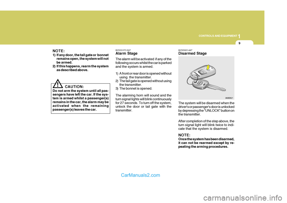
3) The bonnet is opened.The alarming horn will sound and the turn signal lights will blink continuouslyfor 27 seconds. To turn off the system, unlock the door or tail gate with the transmitter. B070D02O-AAT Disarmed Stage The system will be disarmed when the driver's or passenger's door is unlocked by depressing the "UNLOCK" button onthe transmitter. After completion of the step above, the turn signal light will blink twice to indi- cate that the system is disarmed. NOTE: Once the system has been disarmed, it can not be rearmed except by re-peating the arming procedures.
3A9BA21
Page 290 of 490
1CONTROLS AND EQUIPMENT
10
B070F01A-EAT Keyless Entry System (Not all models) Locking doors
1. Close all doors.
2. Push the "LOCK" button on the trans-mitter.
3. At the same time all doors lock, the
turn signal light will blink once toindicate that the system is armed.
Unlocking doors
1. Push the "UNLOCK" button on the transmitter.
2. At the same time all doors unlock,
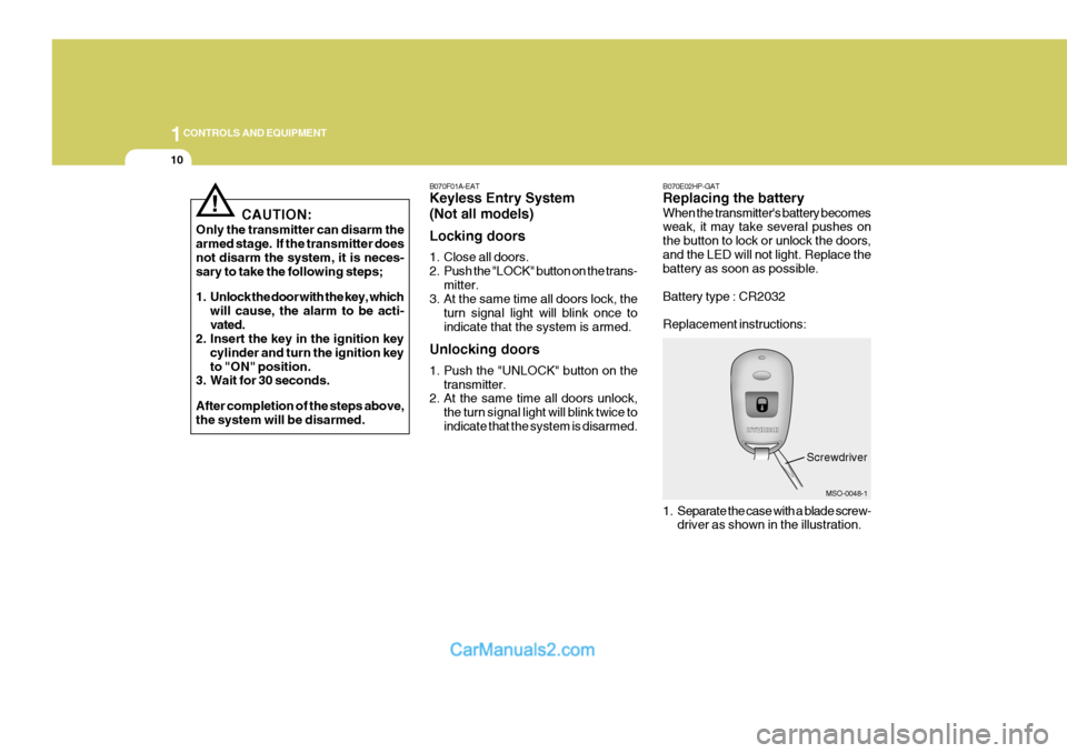
the turn signal light will blink twice to indicate that the system is disarmed. B070E02HP-GAT Replacing the battery When the transmitter's battery becomes weak, it may take several pushes on the button to lock or unlock the doors,and the LED will not light. Replace the battery as soon as possible. Battery type : CR2032 Replacement instructions:
1. Separate the case with a blade screw-
driver as shown in the illustration.
MSO-0048-1
Screwdriver
CAUTION:
Only the transmitter can disarm the armed stage. If the transmitter does not disarm the system, it is neces- sary to take the following steps;
1. Unlock the door with the key, which will cause, the alarm to be acti- vated.
2. Insert the key in the ignition key
cylinder and turn the ignition keyto "ON" position.
3. Wait for 30 seconds. After completion of the steps above, the system will be disarmed.
!
Page 301 of 490
1
CONTROLS AND EQUIPMENT
21
!
If the height of the adjusting seat belt is too near your neck, you will not begetting the most effective protection. The shoulder portion should be ad- justed so that it lies across your chestand midway over your shoulder nearest the door and not your neck. To adjust the height of the seat beltanchor, lower or raise the height ad- juster into an appropriate position. To raise the height adjuster, pull it up. Tolower it, push it down whilst pressing the height adjuster button. Release the button to lock the anchorinto position. Try sliding the release button to make sure that it has locked into position.
WARNING:
o The height adjuster must be in the locked position when the vehicleis moving.
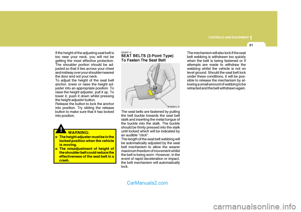
o The misadjustment of height of the shoulder belt could reduce theeffectiveness of the seat belt in acrash. SB090P1-E SEAT BELTS (3-Point Type) To Fasten The Seat Belt The seat belts are fastened by pulling the belt buckle towards the seat belt stalk and inserting the metal tongue of the buckle into the stalk. The buckleshould be firmly pressed into the stalk until locked which will be indicated by an audible "click".The length of the seat belt webbing will be automatically adjusted by the seat belt mechanism to allow the wearermaximum freedom of movement whilst the belt is being worn. However, in the event of rapid deceleration or impact,the belt mechanism will automatically lock. The mechanism will also lock if the seat belt webbing is withdrawn too quicklywhen the belt is being fastened or if attempts are made to withdraw the webbing whilst the vehicle is not onlevel ground. Should the seat belt lock under these conditions, it will be pos- sible to release the mechanism by al-lowing a small amount of webbing to be retracted and the belt withdrawn again.
B180A01L-R
Page 302 of 490

1CONTROLS AND EQUIPMENT
22
SB090R1-F To Release the Seat Belt
The seat belt is released by pressing the release button in the locking buckle. When it is released, the belt should auto- matically draw back into the retractor.If this does not happen, check the belt to be sure it is not twisted, then try again. B220A01FC-EAT SEAT BELTS - Centre Rear Seat 3-Point System With EmergencyLocking Retractor(Not all models)
1. Before fastening the rear seat centre
belt, confirm the metal tab (a) and buckle (b) are latched together.
2. After confirming that (a) and (b) are
latched, pull the seat belt out of theretractor and insert the metal tab (c) into the buckle (d).
B220A01FC
B210A01L-R
B200A01S-GAT Adjusting Your Seat Belt You should place the belt as low as possible on your hips, not on your waist. If the belt is located too high on yourbody, you could slide under it in case of accident or a sudden stop. This could result of death, serious injury or prop-erty damage. Both arms should not be under or over the belt. Rather, one should be over and the other under, asshown in the illustration. Never wear the seat belt under the arm nearest to the door.B200A01L-D
Page 303 of 490

1
CONTROLS AND EQUIPMENT
23
There will be an audible "click" when the tab locks in the buckle. The seat beltautomatically adjusts to the proper length only after the lap belt is adjusted manu- ally so that it fits snugly around yourhips. If you lean forward in a slow, easy motion, the belt will extend and let you move around. If there is a sudden stopor impact, the belt will lock into position. It will also lock if you try to lean forward too quickly.
B220A02Y-D
!
!WARNING:
o When using the rear seat centre belt, you must lock all metal tabs and buckles. If any metal tab or buckle is not locked, it will in-crease the chance of injury in the event of collision.
o Never unlock the metal tab (a) and
the buckle (b) with the followingexceptions.
(1) In case of folding rear seatbacks
down.
(2) If transporting an object on the
rear seat may cause damage tothe rear seat centre belt.
o Lock the metal tab (a) and the
buckle (b) immediately after fold-ing rear seatbacks up. B220C01A-EAT To Release the Seat Belt
When you want to release the seat belt, press the button in the locking buckle.
WARNING:
The centre lap belt latching mecha-nism is different from those for the rear seat shoulder belts. When fas- tening the rear seat shoulder belts orthe centre lap belt, make sure they are inserted into the correct buckles to obtain maximum protection fromthe seat belt system and assure proper operation.
B220C02FC
Page 339 of 490
1
CONTROLS AND EQUIPMENT
59
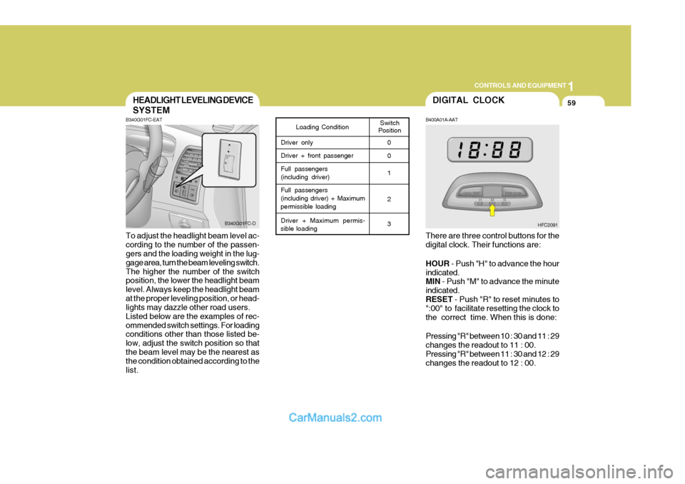
B340G01FC-EAT To adjust the headlight beam level ac- cording to the number of the passen- gers and the loading weight in the lug- gage area, turn the beam leveling switch.The higher the number of the switch position, the lower the headlight beam level. Always keep the headlight beamat the proper leveling position, or head- lights may dazzle other road users. Listed below are the examples of rec-ommended switch settings. For loading conditions other than those listed be- low, adjust the switch position so thatthe beam level may be the nearest as the condition obtained according to the list.
HEADLIGHT LEVELING DEVICE
SYSTEM
Switch
PositionLoading Condition
Driver only Driver + front passengerFull passengers (including driver) Full passengers (including driver) + Maximum
permissible loading
Driver + Maximum permis-
sible loading 0 0 1 2 3
B340G01FC-D
DIGITAL CLOCK
HFC2091
B400A01A-AAT There are three control buttons for the digital clock. Their functions are: HOUR
- Push "H" to advance the hour
indicated. MIN - Push "M" to advance the minute
indicated. RESET - Push "R" to reset minutes to
":00" to facilitate resetting the clock tothe correct time. When this is done: Pressing "R" between 10 : 30 and 11 : 29 changes the readout to 11 : 00.Pressing "R" between 11 : 30 and 12 : 29 changes the readout to 12 : 00.
Page 342 of 490

1CONTROLS AND EQUIPMENT
62
B450B02FC-EAT Rear Drink Holder (Not all models) The rear drink holder is located on the rear main console for holding cups. The rear drink holder can be used by pushing the knob on the rear mainconsole downward and then releasing it.
HFC2098
!
CAUTION:
Place the drink holder in its original position whilst not in use.
!WARNING:
o Use caution when using the drink holders. A spilled beverage that is very hot can injure you or your passengers. Spilled liquids candamage interior trim and electri- cal components.
o Do not place objects other than
cups or drinks in the drink holder.Such objects can be thrown out in the event of a sudden stop or anaccident, possibly injuring the pas- sengers in the vehicle.
SB380A1-E The parking brake must always be set when the vehicle is to be left unat-tended. When the parking brake is ap- plied, and the ignition key is at the "ON" position, the parking brake warning light will be illuminated. Before driving the vehicle, the parking brake must be fully released and the warning light extin- guished.
o To set the parking brake, apply thefoot brake and pull the parking brake lever up with the button depressed. Release the button when the brake is fully applied.
o To release the parking brake, apply
the foot brake and pull up the parking brake lever slightly. Depress the button and lower the lever. B530A01FC-D
PARKING BRAKE
Page 343 of 490

1
CONTROLS AND EQUIPMENT
63
!
B611A02FC-EAT (Not all models) This arm rest is located in the centre of the rear seat back with box. The drink holder in the box can be used by opening the lid of the arm rest. REAR SEAT ARM REST
B610A01FC
!WARNING:
o Do not place objects other than cups or cans in the drink holder. Such objects can be thrown out inthe event of a sudden stop or an accident, possibly injuring the pas- sengers in the vehicle.
o Be careful not to injure your fin- gers when you open the lid of thearm rest.
SUNROOF
SB330A3-E (Not all models) The electrically operated sunroof may be used only whilst the ignition switch is at the "ON" position. The sunroof is equipped with a sunshade which maybe used whilst the sunroof is at the closed position to obscure incoming light.The sunshade is automatically opened whenever the sunroof is opened but must be manually closed by slidingforward after the sunroof is closed. When the sunroof is opened, the wind deflector will automatically rise to theupper position and will automatically retract when the sunroof is closed.
B470A01FC WARNING:
Never install or remove the sunshade whilst driving. To open the sunroof, depress and hold the button indicated. The button should be released when the sunroof is at the fully open position. The sunroof may beclosed by depressing and holding the button indicated. The button should be released when the sunroof is at the fullyclosed position.
HFC2021