coolant Hyundai Santa Fe 2009 - RHD (UK, Australia) Owner's Guide
[x] Cancel search | Manufacturer: HYUNDAI, Model Year: 2009, Model line: Santa Fe, Model: Hyundai Santa Fe 2009Pages: 269, PDF Size: 9.78 MB
Page 218 of 269
6
DO-IT-YOURSELF MAINTENANCE
11
!
!
CHANGING THE AIR CLEANER FILTER
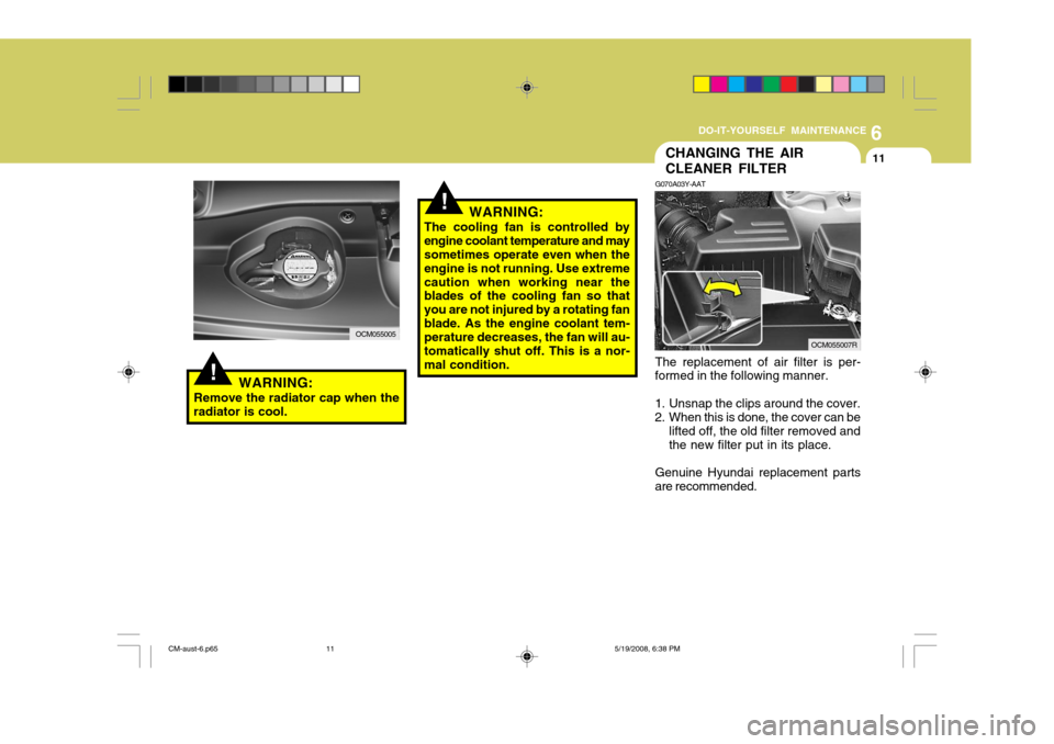
G070A03Y-AAT The replacement of air filter is per-
formed in the following manner.
1. Unsnap the clips around the cover.
2. When this is done, the cover can be lifted off, the old filter removed and the new filter put in its place.
Genuine Hyundai replacement parts
are recommended.
WARNING:
The cooling fan is controlled byengine coolant temperature and may sometimes operate even when the engine is not running. Use extremecaution when working near the blades of the cooling fan so that you are not injured by a rotating fanblade. As the engine coolant tem- perature decreases, the fan will au- tomatically shut off. This is a nor-mal condition.
WARNING:
Remove the radiator cap when the
radiator is cool.
OCM055005OCM055007R
CM-aust-6.p65 5/19/2008, 6:38 PM
11
Page 224 of 269
6
DO-IT-YOURSELF MAINTENANCE
17
!WARNING:
The cooling fan is controlled by engine coolant temperature and may sometimes operate even when the engine is not running. Use extremecaution when working near the blades of the cooling fan, so that you are not injured by a rotating fanblade. As the engine coolant tem- perature decreases, the fan will au- tomatically shut off. This is a nor-mal condition.
CHECKING THE BRAKES
G120A01A-AAT
! CAUTION:
Because brakes are essential to the
safe operation of the car, it is sug- gested that they be checked andinspected by your Hyundai dealer. The brakes should be checked and inspected for wear at those intervalsspecified in the vehicle maintenance schedule in Section 5.!WARNING (DIESEL ONLY):
Never work on injection system with
engine running or within 30 sec- onds after shutting off engine. High pressure pump, rail, injectors andhigh pressure pipes are subject to high pressure even after the engine stopped. The fuel jet produced byfuel leaks may cause serious injury, if it touch the body. People using pacemakers should not move than30cm closer to the ECU or wiring harness within the engine room while engine is running, since the high currents in the Common Rail system produce considerable mag-netic fields.
CM-aust-6.p65 5/19/2008, 6:38 PM
17
Page 233 of 269
6DO-IT-YOURSELF MAINTENANCE
26
!
POWER STEERING FLUID LEVELCHECKING ELECTRIC COOLING FANS
G220A01A-AAT
WARNING:
The cooling fan is controlled by engine coolant temperature and maysometimes operate even when the engine is not running. Use extreme caution when working near theblades of the cooling fan, so that you are not injured by a rotating fan blade. As the coolant temperaturedecreases the fan will automatically shut off. This is a normal condition.
G220B01A-AAT
Checking Engine Cooling Fan
The engine coolant fan should come
on automatically if the engine coolant temperature is high. G220C01A-AAT Checking Condenser Cooling Fan The condenser cooling fan should come on automatically whenever the air con- ditioning is in operation. G230A03A-GAT The power steering fluid level should
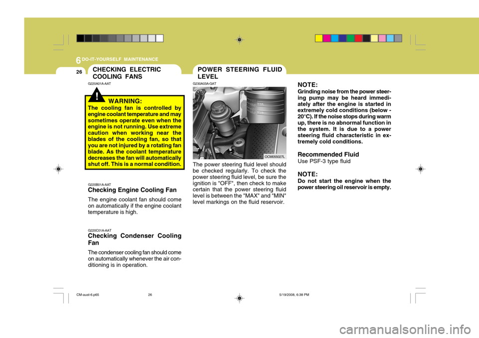
be checked regularly. To check the power steering fluid level, be sure theignition is "OFF", then check to make certain that the power steering fluid level is between the "MAX" and "MIN"level markings on the fluid reservoir.
OCM055027L NOTE: Grinding noise from the power steer-
ing pump may be heard immedi- ately after the engine is started in extremely cold conditions (below - 20°C). If the noise stops during warmup, there is no abnormal function in the system. It is due to a power steering fluid characteristic in ex-tremely cold conditions. Recommended Fluid
Use PSF-3 type fluidNOTE: Do not start the engine when the
power steering oil reservoir is empty.
CM-aust-6.p65 5/19/2008, 6:38 PM
26
Page 235 of 269
6DO-IT-YOURSELF MAINTENANCE
28
OCM055007L
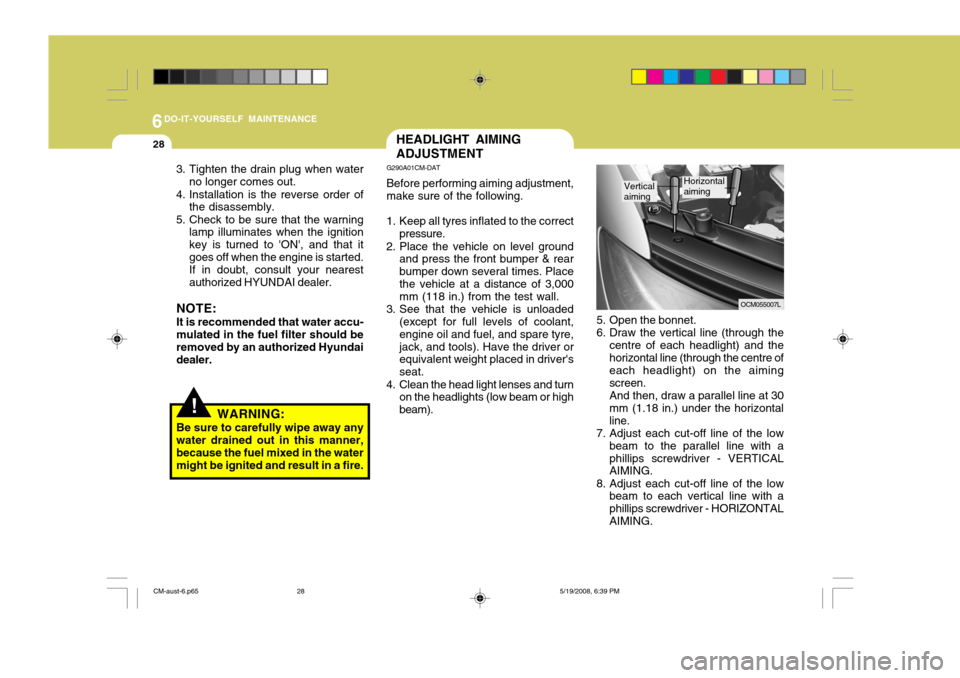
5. Open the bonnet.
6. Draw the vertical line (through the centre of each headlight) and thehorizontal line (through the centre of each headlight) on the aiming screen.And then, draw a parallel line at 30mm (1.18 in.) under the horizontalline.
7. Adjust each cut-off line of the low
beam to the parallel line with aphillips screwdriver - VERTICAL AIMING.
8. Adjust each cut-off line of the low beam to each vertical line with a phillips screwdriver - HORIZONTALAIMING.
Vertical aimingHorizontal aiming
HEADLIGHT AIMING ADJUSTMENT
G290A01CM-DAT Before performing aiming adjustment, make sure of the following.
1. Keep all tyres inflated to the correct pressure.
2. Place the vehicle on level ground and press the front bumper & rear bumper down several times. Placethe vehicle at a distance of 3,000 mm (118 in.) from the test wall.
3. See that the vehicle is unloaded (except for full levels of coolant, engine oil and fuel, and spare tyre,jack, and tools). Have the driver or equivalent weight placed in driver's seat.
4. Clean the head light lenses and turn on the headlights (low beam or highbeam).
!WARNING:
Be sure to carefully wipe away any water drained out in this manner, because the fuel mixed in the watermight be ignited and result in a fire.
3. Tighten the drain plug when water
no longer comes out.
4. Installation is the reverse order of the disassembly.
5. Check to be sure that the warning lamp illuminates when the ignitionkey is turned to 'ON', and that itgoes off when the engine is started.If in doubt, consult your nearestauthorized HYUNDAI dealer.
NOTE: It is recommended that water accu- mulated in the fuel filter should be removed by an authorized Hyundai dealer.
CM-aust-6.p65 5/19/2008, 6:39 PM
28
Page 250 of 269
7EMISSION CONTROL SYSTEMS
2EMISSION CONTROL SYSTEM
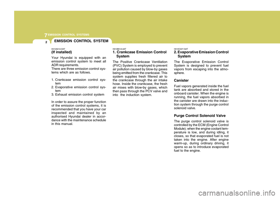
H010A01A-DAT (If installed) Your Hyundai is equipped with an emission control system to meet all ADR requirements. There are three emission control sys- tems which are as follows.
1. Crankcase emission control sys- tem
2. Evaporative emission control sys- tem
3. Exhaust emission control systemIn order to assure the proper function of the emission control systems, it is recommended that you have your carinspected and maintained by an authorised Hyundai dealer in accor- dance with the maintenance schedulein this manual. H010B01A-AAT
1. Crankcase Emission Control
System
The Positive Crankcase Ventilation
(PVC) System is employed to prevent air pollution caused by blow-by gases being emitted from the crankcase. Thissystem supplies fresh filtered air to the crankcase through the air intake hose. Inside the crankcase, the freshair mixes with blow-by gases, which then pass through the PCV valve and into the induction system. H010C02Y-GAT
2. Evaporative Emission Control
System
The Evaporative Emission Control
System is designed to prevent fuel vapors from escaping into the atmo- sphere. Canister
Fuel vapors generated inside the fuel
tank are absorbed and stored in the onboard canister. When the engine isrunning, the fuel vapors absorbed in the canister are drawn into the induc- tion system through the purge controlsolenoid valve. Purge Control Solenoid Valve
The purge control solenoid valve is
controlled by the ECM (Engine Control Module); when the engine coolant tem- perature is low, and during idling, it closes, so that evaporated fuel is nottaken into the engine. After engine warm-up, during ordinary driving, it opens so as to introduce evaporatedfuel to the engine.
Page 263 of 269
9VEHICLE SPECIFICATIONS
4LUBRICATION CHART
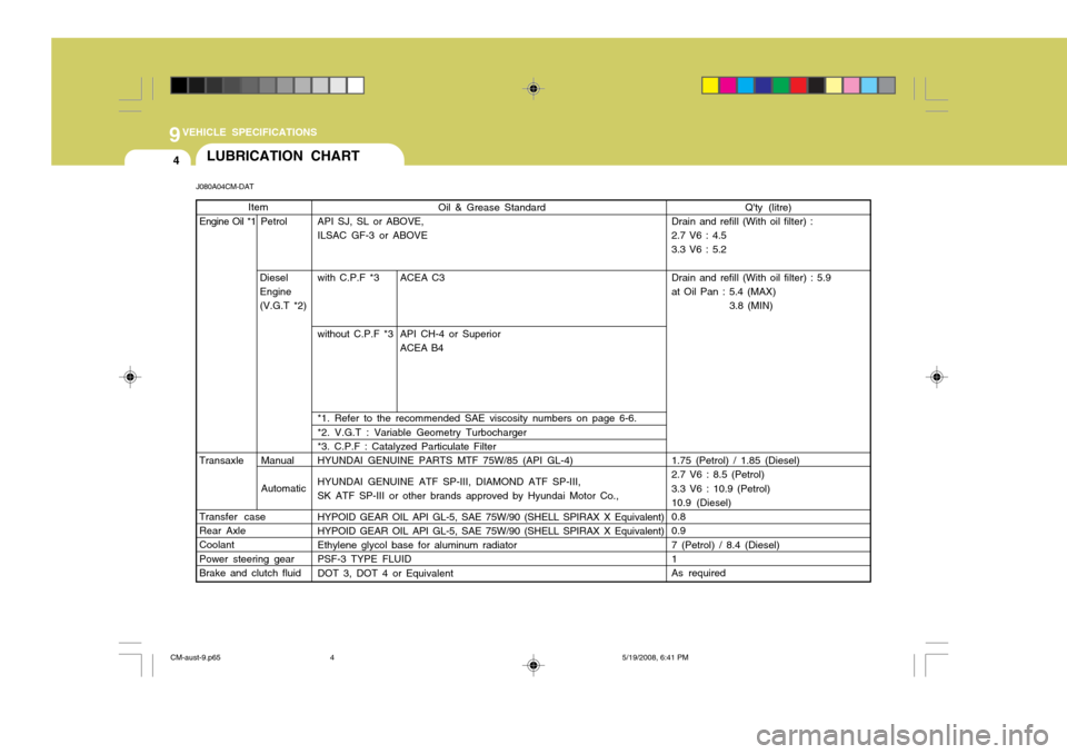
Q'ty (litre)
Drain and refill (With oil filter) : 2.7 V6 : 4.5 3.3 V6 : 5.2 Drain and refill (With oil filter) : 5.9 at Oil Pan : 5.4 (MAX) 3.8 (MIN)
1.75 (Petrol) / 1.85 (Diesel) 2.7 V6 : 8.5 (Petrol) 3.3 V6 : 10.9 (Petrol) 10.9 (Diesel) 0.8 0.9 7 (Petrol) / 8.4 (Diesel) 1 As required
Item
Engine Oil *1 Petrol
Diesel
Engine
(V.G.T *2)
Transaxle Manual Automatic
Transfer caseRear Axle Coolant Power steering gear Brake and clutch fluid
Oil & Grease Standard
API SJ, SL or ABOVE, ILSAC GF-3 or ABOVE
with C.P.F *3 ACEA C3
without C.P.F *3 API CH-4 or Superior
ACEA B4
*1. Refer to the recommended SAE viscosity numbers on page 6-6. *2. V.G.T : Variable Geometry Turbocharger *3. C.P.F : Catalyzed Particulate Filter HYUNDAI GENUINE PARTS MTF 75W/85 (API GL-4) HYUNDAI GENUINE ATF SP-III, DIAMOND ATF SP-III, SK ATF SP-III or other brands approved by Hyundai Motor Co., HYPOID GEAR OIL API GL-5, SAE 75W/90 (SHELL SPIRAX X Equivalent) HYPOID GEAR OIL API GL-5, SAE 75W/90 (SHELL SPIRAX X Equivalent) Ethylene glycol base for aluminum radiator PSF-3 TYPE FLUID DOT 3, DOT 4 or Equivalent
J080A04CM-DAT
CM-aust-9.p65
5/19/2008, 6:41 PM
4
Page 266 of 269
3
10
INDEX
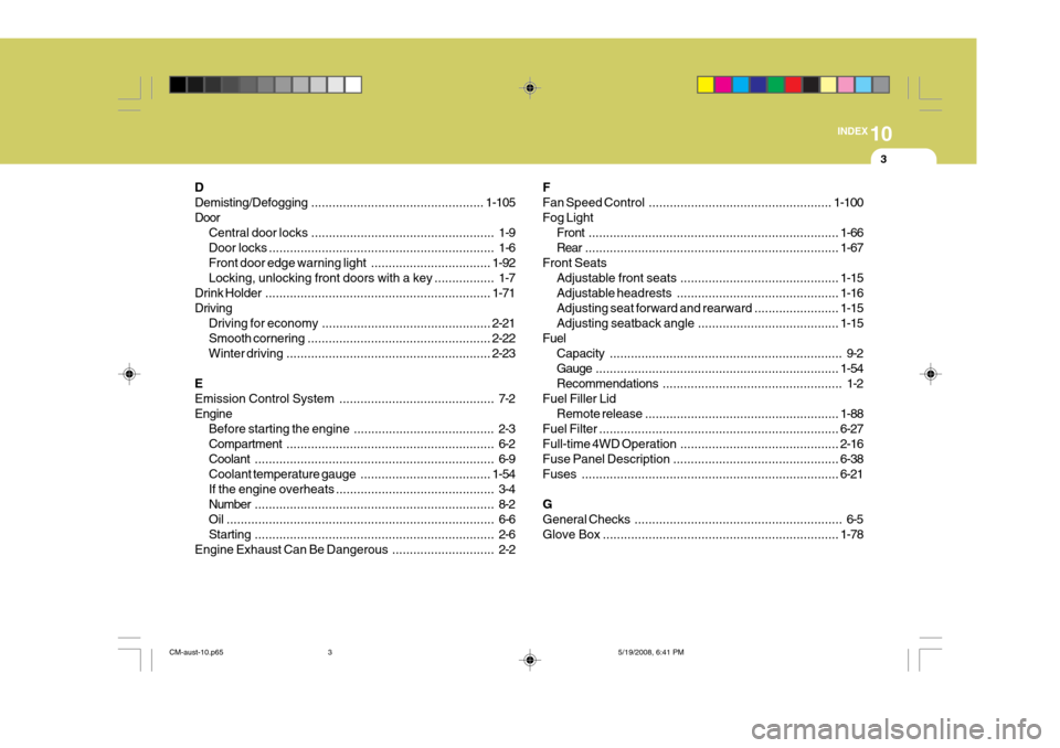
D Demisting/Defogging
................................................. 1-105
Door Central door locks .................................................... 1-9
Door locks ................................................................ 1-6
Front door edge warning light ..................................1-92
Locking, unlocking front doors with a key ................. 1-7
Drink Holder ................................................................ 1-71
Driving Driving for economy ................................................ 2-21
Smooth cornering .................................................... 2-22
Winter driving .......................................................... 2-23
EEmission Control System ............................................ 7-2
Engine Before starting the engine ........................................ 2-3Compartment ........................................................... 6-2
Coolant .................................................................... 6-9
Coolant temperature gauge .....................................1-54
If the engine overheats ............................................. 3-4
Number .................................................................... 8-2
Oil ............................................................................ 6-6Starting .................................................................... 2-6
Engine Exhaust Can Be Dangerous ............................. 2-2FFan Speed
Control .................................................... 1-100
Fog Light Front ....................................................................... 1-66
Rear ........................................................................ 1-67
Front Seats Adjustable front seats ............................................. 1-15
Adjustable headrests .............................................. 1-16
Adjusting seat forward and rearward ........................ 1-15
Adjusting seatback angle .. ......................................1-15
Fuel Capacity .................................................................. 9-2
Gauge ..................................................................... 1-54
Recommendations ................................................... 1-2
Fuel Filler Lid Remote release ....................................................... 1-88
Fuel Filter .................................................................... 6-27
Full-time 4 WD Operation ............................................. 2-16
Fuse Panel Description ............................................... 6-38
Fuses ......................................................................... 6-21
GGeneral Checks ........................................................... 6-5
Glove Box ................................................................... 1-78
CM-aust-10.p65 5/19/2008, 6:41 PM
3