ignition Hyundai Sonata 2014 Owner's Manual
[x] Cancel search | Manufacturer: HYUNDAI, Model Year: 2014, Model line: Sonata, Model: Hyundai Sonata 2014Pages: 665, PDF Size: 17.43 MB
Page 17 of 665
F17F17
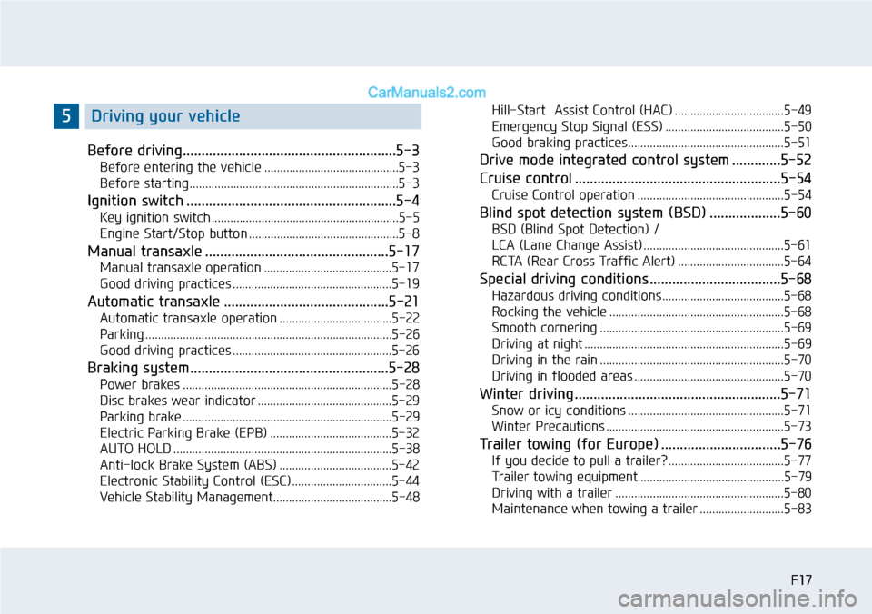
Before driving.........................................................5-3
Before entering the vehicle ...........................................5-3
Before starting...................................................................5-3
Ignition switch ........................................................5-4
Key ignition switch ............................................................5-5
Engine Start/Stop button ................................................5-8
Manual transaxle .................................................5-17
Manual transaxle operation .........................................5-17
Good driving practices ...................................................5-19
Automatic transaxle ............................................5-21
Automatic transaxle operation ....................................5-22
Parking ...............................................................................5-26
Good driving practices ...................................................5-26
Braking system.....................................................5-28
Power brakes ...................................................................5-28
Disc brakes wear indicator ...........................................5-29
Parking brake ...................................................................5-29
Electric Parking Brake (EPB) .......................................5-32
AUTO HOLD ......................................................................5-38
Anti-lock Brake System (ABS) ....................................5-42
Electronic Stability Control (ESC)................................5-44
Vehicle Stability Management......................................5-48
Hill-Start Assist Control (HAC) ...................................5-49
Emergency Stop Signal (ESS) ......................................5-50
Good braking practices..................................................5-51
Drive mode integrated control system .............5-52
Cruise control .......................................................5-54
Cruise Control operation ...............................................5-54
Blind spot detection system (BSD) ...................5-60
BSD (Blind Spot Detection) /
LCA (Lane Change Assist) .............................................5-61
RCTA (Rear Cross Traffic Alert) ..................................5-64
Special driving conditions ...................................5-68
Hazardous driving conditions.......................................5-68
Rocking the vehicle ........................................................5-68
Smooth cornering ...........................................................5-69
Driving at night ................................................................5-69
Driving in the rain ...........................................................5-70
Driving in flooded areas ................................................5-70
Winter driving .......................................................5-71
Snow or icy conditions ..................................................5-71
Winter Precautions .........................................................5-73
Tr a i l e r t o w i n g ( fo r E u r o p e ) . . . . . . . . . . . . . . . . . . . . . . . . . . . . . . . . 5 - 7 6
If you decide to pull a trailer? .....................................5-77
Tr a i l e r t o w i n g e q u i p m e n t . . . . . . . . . . . . . . . . . . . . . . . . . . . . . . . . . . . . . . . . . . . . . . 5 - 7 9
Driving with a trailer ......................................................5-80
Maintenance when towing a trailer ...........................5-83
5Driving your vehicle
Page 27 of 665
1-6
Yo u r v e h i c l e a t a g l a n c e
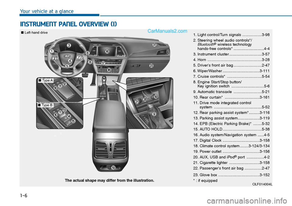
INSTRUMENT PANEL OVERVIEW (I)
1. Light control/Turn signals ..................3-98
2. Steering wheel audio controls*/Bluetooth®wireless technology hands-free controls* ............................4-4
3. Instrument cluster ..............................3-57
4. Horn ..................................................3-28
5. Driver's front air bag ..........................2-47
6. Wiper/Washer ..................................3-111
7. Cruise controls* ................................5-54
8. Engine Start/Stop button/Key ignition switch ..............................5-6
9. Automatic transaxle ..........................5-21
10. Rear curtain* ................................3-161
11. Drive mode integrated control system ............................................5-52
12. Rear parking assist system*..........3-116
13. Parking assist system....................3-119
14. EPB (Electric Parking Brake)* ........5-32
15. AUTO HOLD ....................................5-38
16. Audio system/Navigation system ......4-5
17. Digital Clock ..................................3-158
18. Climate control system ........3-124/3-134
19. Power outlet ..................................3-156
20. AUX, USB and iPod®port ................4-2
21. Cigarette lighter ............................3-158
22. Passenger's front air bag ................2-47
23. Glove box ......................................3-152
* : if equippedOLF014004LThe actual shape may differ from the illustration.
■Type A
■Type B
■Left-hand drive
Page 28 of 665
1-7
Yo u r v e h i c l e a t a g l a n c e
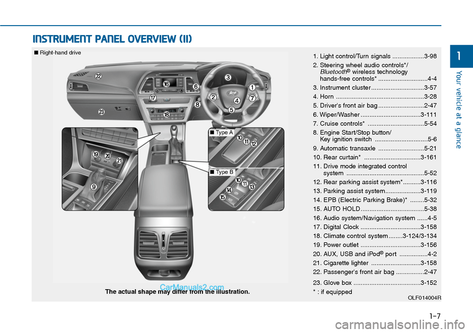
INSTRUMENT PANEL OVERVIEW (II)
11. Light control/Turn signals ..................3-98
2. Steering wheel audio controls*/Bluetooth®wireless technology hands-free controls* ............................4-4
3. Instrument cluster ..............................3-57
4. Horn ..................................................3-28
5. Driver's front air bag ..........................2-47
6. Wiper/Washer ..................................3-111
7. Cruise controls* ................................5-54
8. Engine Start/Stop button/Key ignition switch ..............................5-6
9. Automatic transaxle ..........................5-21
10. Rear curtain* ................................3-161
11. Drive mode integrated control system ............................................5-52
12. Rear parking assist system*..........3-116
13. Parking assist system....................3-119
14. EPB (Electric Parking Brake)* ........5-32
15. AUTO HOLD ....................................5-38
16. Audio system/Navigation system ......4-5
17. Digital Clock ..................................3-158
18. Climate control system ........3-124/3-134
19. Power outlet ..................................3-156
20. AUX, USB and iPod®port ................4-2
21. Cigarette lighter ............................3-158
22. Passenger's front air bag ................2-47
23. Glove box ......................................3-152
* : if equippedOLF014004RThe actual shape may differ from the illustration.
■Type A
■Type B
■Right-hand drive
Page 50 of 665
2-21
Safety system of your vehicle
2
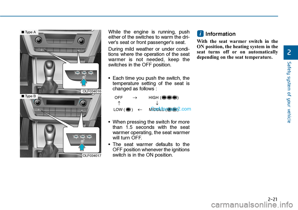
While the engine is running, push
either of the switches to warm the dri-
ver's seat or front passenger's seat.
During mild weather or under condi-
tions where the operation of the seat
warmer is not needed, keep the
switches in the OFF position.
•Each time you push the switch, the
temperature setting of the seat is
changed as follows :
•When pressing the switch for more
than 1.5 seconds with the seat
warmer operating, the seat warmer
will turn OFF.
•The seat warmer defaults to the
OFF position whenever the ignitions
switch is in the ON position.
Information
With the seat warmer switch in the
ON position, the heating system in the
seat turns off or on automatically
depending on the seat temperature.
i
OLF034016
OLF034017
■Type A
■Type BOFF HIGH ( )
LOW ( ) MIDDLE ( )
→→
→
→
Page 51 of 665
2-22
Safety system of your vehicle
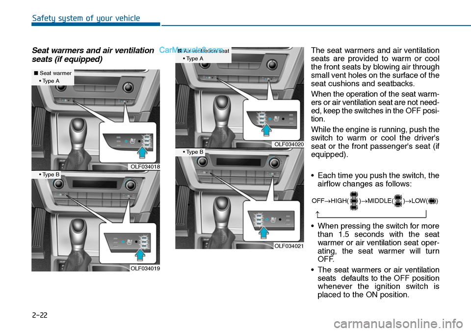
Seat warmers and air ventilation
seats (if equipped)
The seat warmers and air ventilation
seats are provided to warm or cool
the front seats by blowing air through
small vent holes on the surface of the
seat cushions and seatbacks.
When the operation of the seat warm-
ers or air ventilation seat are not need-
ed, keep the switches in the OFF posi-
tion.
While the engine is running, push the
switch to war m or cool the driver's
seat or the front passenger's seat (if
equipped).
•Each time you push the switch, the
airflow changes as follows:
•When pressing the switch for more
than 1.5 seconds with the seat
warmer or air ventilation seat oper-
ating, the seat warmer will turn
OFF.
•The seat warmers or air ventilation
seats defaults to the OFF position
whenever the ignition switch is
placed to the ON position.
OFF→HIGH( )→MIDDLE( )→LOW( )
→
OLF034018
OLF034019
■Seat warmer• Type A
• Type B
OLF034020
OLF034021
■Air ventilation seat• Type A
•
• Type B
Page 53 of 665
2-24
Safety system of your vehicle
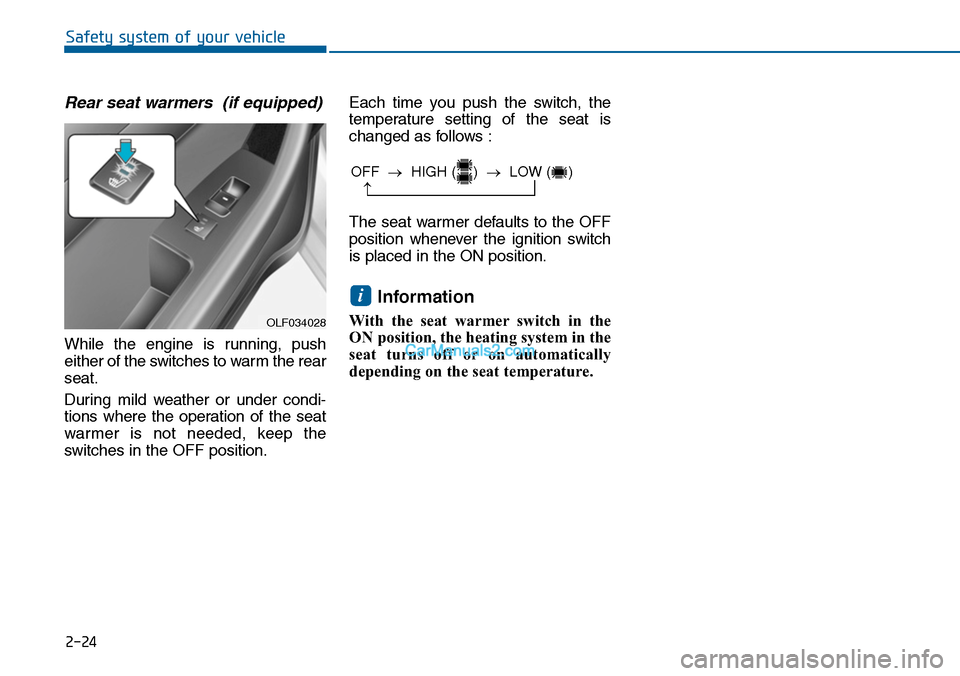
Rear seat warmers (if equipped)
While the engine is running, push
either of the switches to warm the rear
seat.
During mild weather or under condi-
tions where the operation of the seat
warmer is not needed, keep the
switches in the OFF position.
Each time you push the switch, the
temperature setting of the seat is
changed as follows :
The seat warmer defaults to the OFF
position whenever the ignition switch
is placed in the ON position.
Information
With the seat warmer switch in the
ON position, the heating system in the
seat turns off or on automatically
depending on the seat temperature.
i
OFF →HIGH ( ) →LOW ( )
→
OLF034028
Page 55 of 665
2-26
Safety system of your vehicle
Seat belt warning light
Seat belt warning
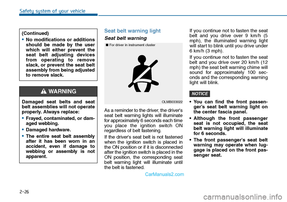
As a reminder to the driver, the driver's
seat belt warning lights will illuminate
for approximately 6 seconds each time
you place the ignition switch ON
regardless of belt fastening.
If the driver's seat belt is not fastened
when the ignition switch is placed in
the ON position or if it is disconnected
after the ignition switch is placed in the
ON position, the corresponding seat
belt warning light will illuminate until
the belt is fastened.
If you continue not to fasten the seat
belt and you drive over 9 km/h (5
mph), the illuminated warning light
will start to blink until you drive under
6 km/h (3 mph).
If you continue not to fasten the seat
belt and you drive over 20 km/h (12
mph) the seat belt warning chime will
sound for approximately 100 sec-
onds and the corresponding warning
light will blink.
•You can find the front passen-
ger’s seat belt warning light on
the center fascia panel.
•Although the front passenger
seat is not occupied, the seat
belt warning light will illuminate
for 6 seconds.
•The front passenger's seat belt
warning may operate when lug-
gage is placed on the front pas-
senger seat.
NOTICE
Damaged seat belts and seat
belt assemblies will not operate
properly. Always replace:
•Frayed, contaminated, or dam-
aged webbing.
•Damaged hardware.
•The entire seat belt assembly
after it has been worn in an
accident, even if damage to
webbing or assembly is not
apparent.
WARNING
(Continued)
•No modifications or additions
should be made by the user
which will either prevent the
seat belt adjusting devices
from operating to remove
slack, or prevent the seat belt
assembly from being adjusted
to remove slack.
OLMB033022
■For driver in instrument cluster
Page 60 of 665
2-31
Safety system of your vehicle
2
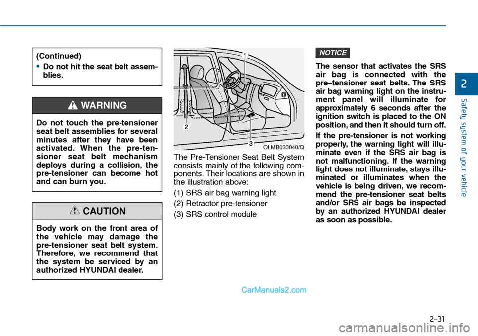
The Pre-Tensioner Seat Belt System
consists mainly of the following com-
ponents. Their locations are shown in
the illustration above:
(1) SRS air bag warning light
(2) Retractor pre-tensioner
(3) SRS control module
The sensor that activates the SRS
air bag is connected with the
pre–tensioner seat belts. The SRS
air bag warning light on the instru-
ment panel will illuminate for
approximately 6 seconds after the
ignition switch is placed to the ON
position, and then it should turn off.
If the pre-tensioner is not working
properly, the warning light will illu-
minate even if the SRS air bag is
not malfunctioning. If the warning
light does not illuminate, stays illu-
minated or illuminates when the
vehicle is being driven, we recom-
mend the pre-tensioner seat belts
and/or SRS air bags be inspected
by an authorized HYUNDAI dealer
as soon as possible.
NOTICE(Continued)
•Do not hit the seat belt assem-
blies.
Do not touch the pre-tensioner
seat belt assemblies for several
minutes after they have been
activated. When the pre-ten-
sioner seat belt mechanism
deploys during a collision, the
pre-tensioner can become hot
and can burn you.
WARNING
Body work on the front area of
the vehicle may damage the
pre-tensioner seat belt system.
Therefore, we recommend that
the system be serviced by an
authorized HYUNDAI dealer.
CAUTION
OLMB033040/Q
Page 81 of 665
2-52
Safety system of your vehicle
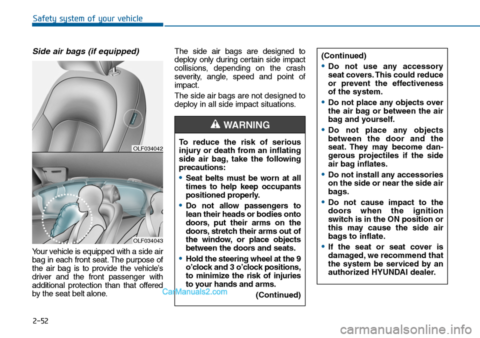
Side air bags (if equipped)
Yo u r v e h i c l e i s e q u i p p e d w i t h a s i d e a i r
bag in each front seat. The purpose of
the air bag is to provide the vehicle’s
driver and the front passenger with
additional protection than that offered
by the seat belt alone.
The side air bags are designed to
deploy only during certain side impact
collisions, depending on the crash
severity, angle, speed and point of
impact.
The side air bags are not designed to
deploy in all side impact situations.
OLF034042
OLF034043
(Continued)
•Do not use any accessory
seat covers. This could reduce
or prevent the effectiveness
of the system.
•Do not place any objects over
the air bag or between the air
bag and yourself.
•Do not place any objects
between the door and the
seat. They may become dan-
gerous projectiles if the side
air bag inflates.
•Do not install any accessories
on the side or near the side air
bags.
•Do not cause impact to the
doors when the ignition
switch is in the ON position or
this may cause the side air
bags to inflate.
•If the seat or seat cover is
damaged, we recommend that
the system be serviced by an
authorized HYUNDAI dealer.
To reduce the risk of serious
injury or death from an inflating
side air bag, take the following
precautions:
•Seat belts must be worn at all
times to help keep occupants
positioned properly.
•Do not allow passengers to
lean their heads or bodies onto
doors, put their arms on the
doors, stretch their arms out of
the window, or place objects
between the doors and seats.
•Hold the steering wheel at the 9
o’clock and 3 o’clock positions,
to minimize the risk of injuries
to your hands and arms.
(Continued)
WARNING
Page 83 of 665
2-54
Safety system of your vehicle
How does the air bags system
operate?
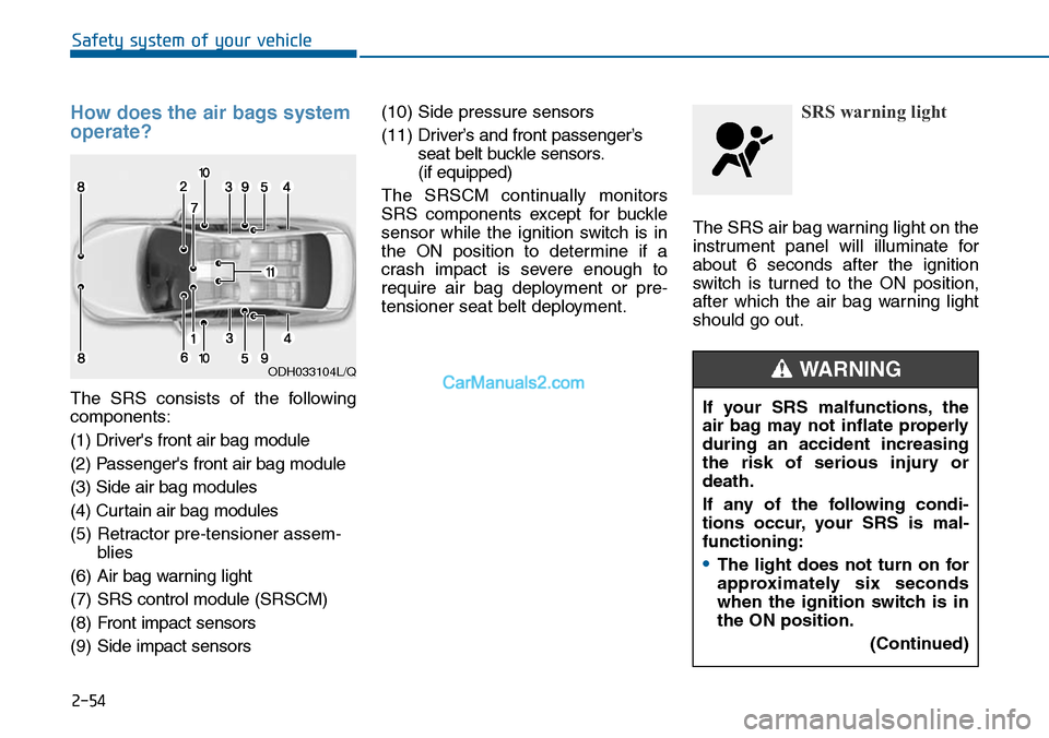
The SRS consists of the following
components:
(1) Driver's front air bag module
(2) Passenger's front air bag module
(3) Side air bag modules
(4) Curtain air bag modules
(5) Retractor pre-tensioner assem-
blies
(6) Air bag warning light
(7) SRS control module (SRSCM)
(8) Front impact sensors
(9) Side impact sensors
(10) Side pressure sensors
(11) Driver’s and front passenger’s
seat belt buckle sensors.
(if equipped)
The SRSCM continually monitors
SRS components except for buckle
sensor while the ignition switch is in
the ON position to determine if a
crash impact is severe enough to
require air bag deployment or pre-
tensioner seat belt deployment.
SRS warning light
The SRS air bag warning light on the
instrument panel will illuminate for
about 6 seconds after the ignition
switch is tur ned to the ON position,
after which the air bag warning light
should go out.
ODH033104L/Q
If your SRS malfunctions, the
air bag may not inflate properly
during an accident increasing
the risk of serious injury or
death.
If any of the following condi-
tions occur, your SRS is mal-
functioning:
•The light does not turn on for
approximately six seconds
when the ignition switch is in
the ON position.
(Continued)
WARNING