charging Hyundai Sonata 2016 Owner's Manual - RHD (UK, Australia)
[x] Cancel search | Manufacturer: HYUNDAI, Model Year: 2016, Model line: Sonata, Model: Hyundai Sonata 2016Pages: 504, PDF Size: 12.45 MB
Page 170 of 504
3-86
Convenient features of your vehicle
Charging System
Warning Light
This warning light illuminates:
• Once you set the ignition switch or
the Engine Start/Stop button to the
ON position.
- It remains on until the engine is
started.
• When there is a malfunction with
either the alternator or electrical
charging system.
If there is a malfunction with either
the alternator or electrical charging
system:
1. Drive carefully to the nearest safe
location and stop your vehicle.
2. Turn the engine off and check the
alternator drive belt for looseness
or breakage.
If the belt is adjusted properly,
there may be a problem in the
electrical charging system.
In this case, we recommend that
you have the vehicle inspected by
an authorised HYUNDAI dealer as
soon as possible.
Engine Oil Pressure
Warning Light
This warning light illuminates:
• Once you set the ignition switch or
the Engine Start/Stop button to the
ON position.
- It remains on until the engine is
started.
• When the engine oil pressure is low.
If the engine oil pressure is low:
1. Drive carefully to the nearest safe
location and stop your vehicle.
2. Turn the engine off and check the
engine oil level (For more details,
refer to “Engine Oil” in chapter 7).
If the level is low, add oil as required.
If the warning light remains on
after adding oil or if oil is not avail-
able, we recommend that you
have the vehicle inspected by an
authorised HYUNDAI dealer as
soon as possible.
Page 185 of 504
3-101
Convenient features of your vehicle
3
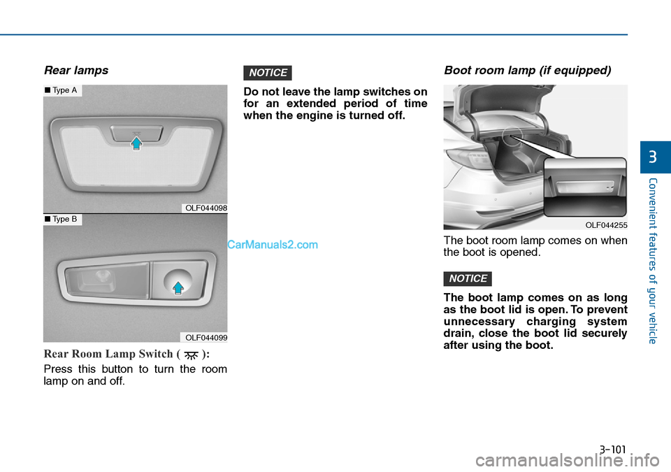
Rear lamps
Rear Room Lamp Switch ( ):
Press this button to turn the room
lamp on and off.Do not leave the lamp switches on
for an extended period of time
when the engine is turned off.
Boot room lamp (if equipped)
The boot room lamp comes on when
the boot is opened.
The boot lamp comes on as long
as the boot lid is open. To prevent
unnecessary charging system
drain, close the boot lid securely
after using the boot.
NOTICE
NOTICE
OLF044255
OLF044098
OLF044099
■Type A
■Type B
Page 186 of 504
3-102
Convenient features of your vehicle
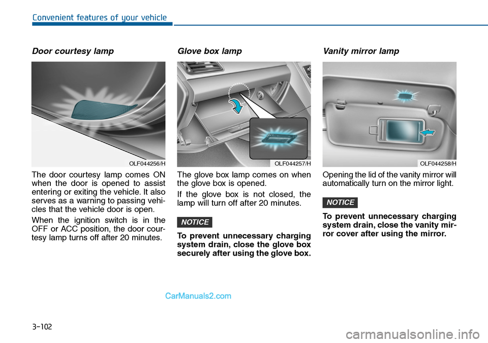
Door courtesy lamp
The door courtesy lamp comes ON
when the door is opened to assist
entering or exiting the vehicle. It also
serves as a warning to passing vehi-
cles that the vehicle door is open.
When the ignition switch is in the
OFF or ACC position, the door cour-
tesy lamp turns off after 20 minutes.
Glove box lamp
The glove box lamp comes on when
the glove box is opened.
If the glove box is not closed, the
lamp will turn off after 20 minutes.
To prevent unnecessary charging
system drain, close the glove box
securely after using the glove box.
Vanity mirror lamp
Opening the lid of the vanity mirror will
automatically turn on the mirror light.
To prevent unnecessary charging
system drain, close the vanity mir-
ror cover after using the mirror.
NOTICE
NOTICE
OLF044257/HOLF044258/HOLF044256/H
Page 254 of 504
4-15
Multimedia System
4
(Continued)
• When using mass storage USB
devices with separate logical drives,
only files saved to the root drive can
be played.
• Files may not properly operate if
application programs are installed
to the USBs.
• The device may not operate normal-
ly if MP3 Players, cellular phones,
digital cameras, or other electronic
devices (USB devices not recognized
as portable disk drives) are connect-
ed with the device.
• Charging through the USB may not
work for some mobile devices.
• The device may not support normal
operation when using a USB memo-
ry type besides (Metal Cover Type)
USB Memory.
(Continued)(Continued)
• The device may not support normal
operation when using formats such
as HDD Type, CF, or SD Memory.
• The device will not support files
locked by DRM (Digital Rights
Management.)
• USB memory sticks used by con-
necting an Adaptor (SD Type or CF
Type) may not be properly recog-
nized.
• The device may not operate proper-
ly when using USB HDDs or USBs
subject to connection failures
caused by vehicle vibrations. (e.g. i-
stick type)
(Continued)(Continued)
• Avoid use of USB mem-
ory products that can
also be used as key
chains or mobile phone
accessories. Use of such
products may cause damage to the
USB jack.
• Connecting an MP3 device or phone
through various channels, such as
AUX/BT or Audio/ USB mode may
result in pop noises or abnormal
operation.
Page 256 of 504
4-17
Multimedia System
4
(Continued)
• Some iPod
®s may not sync with the
System depending on its version. If
the Media is removed before the
Media is recognized, then the sys-
tem may not properly restore the
previously operated mode. (iPad
®
charging is not supported.)
Information
-
Using the AUX device
• If an external device connector is
connected with the AUX terminal,
then AUX mode will automatically
operate. Once the connector is dis-
connected, the previous mode will
be restored.
• AUX mode can be used only when
an external audio player (cam-
corder, car VCR, etc.) has been con-
nected.
• The AUX volume can be controlled
separately from other audio modes.
• Connecting a connector jack to the
AUX terminal without an external
device will convert the system to
AUX mode, but only output noise.
When an external device is not
being used, also remove the connec-
tor jack.
(Continued)(Continued)
• When the external device power is
connected to the power jack, play-
ing the external device may output
noise. In such cases, disconnect the
power connection before use.
• Fully insert the AUX cable to the
AUX jack upon use.
i
Page 319 of 504
5-6
Driving your vehicle
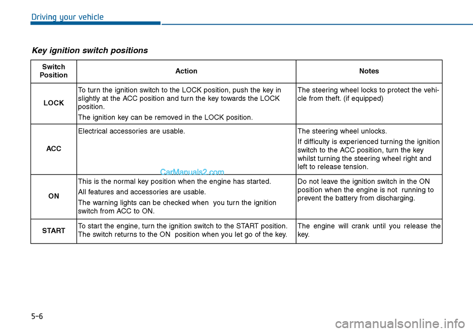
Key ignition switch positions
Switch
PositionActionNotes
LOCK
To turn the ignition switch to the LOCK position, push the key in
slightly at the ACC position and turn the key towards the LOCK
position.
The ignition key can be removed in the LOCK position.The steering wheel locks to protect the vehi-
cle from theft. (if equipped)
ACC
Electrical accessories are usable.The steering wheel unlocks.
If difficulty is experienced turning the ignition
switch to the ACC position, turn the key
whilst turning the steering wheel right and
left to release tension.
ON
This is the normal key position when the engine has started.
All features and accessories are usable.
The warning lights can be checked when you turn the ignition
switch from ACC to ON.Do not leave the ignition switch in the ON
position when the engine is not running to
prevent the battery from discharging.
STARTTo start the engine, turn the ignition switch to the START position.
The switch returns to the ON position when you let go of the key.The engine will crank until you release the
key.
Page 322 of 504
5-9
Driving your vehicle
5
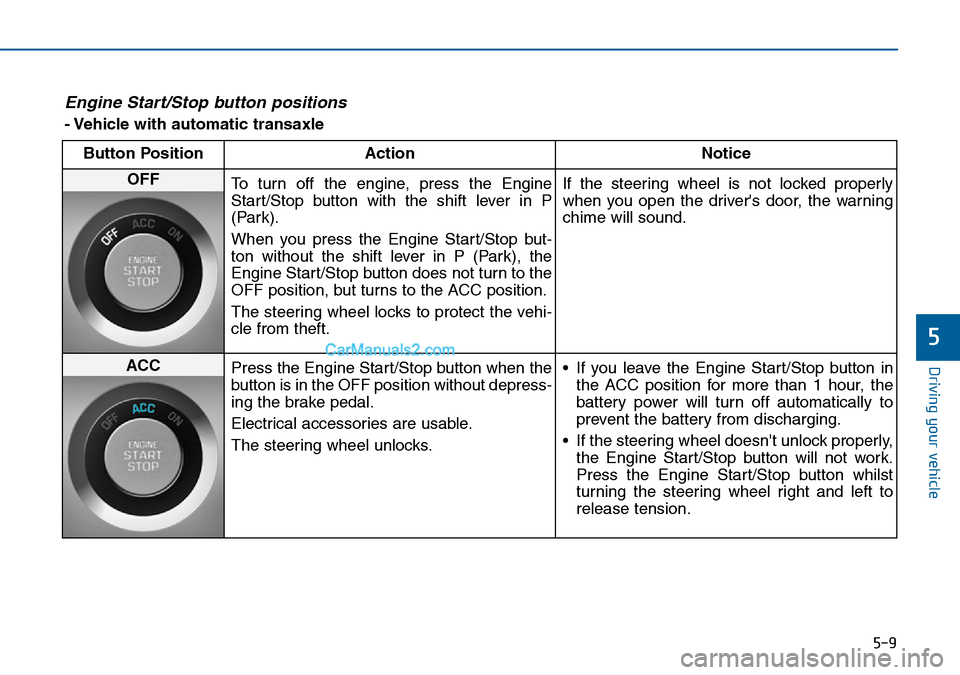
Engine Start/Stop button positions
- Vehicle with automatic transaxle
Button Position Action Notice
OFF
To turn off the engine, press the Engine
Start/Stop button with the shift lever in P
(Park).
When you press the Engine Start/Stop but-
ton without the shift lever in P (Park), the
Engine Start/Stop button does not turn to the
OFF position, but turns to the ACC position.
The steering wheel locks to protect the vehi-
cle from theft.If the steering wheel is not locked properly
when you open the driver's door, the warning
chime will sound.
ACC
Press the Engine Start/Stop button when the
button is in the OFF position without depress-
ing the brake pedal.
Electrical accessories are usable.
The steering wheel unlocks.• If you leave the Engine Start/Stop button in
the ACC position for more than 1 hour, the
battery power will turn off automatically to
prevent the battery from discharging.
• If the steering wheel doesn't unlock properly,
the Engine Start/Stop button will not work.
Press the Engine Start/Stop button whilst
turning the steering wheel right and left to
release tension.
Page 323 of 504
5-10
Driving your vehicle
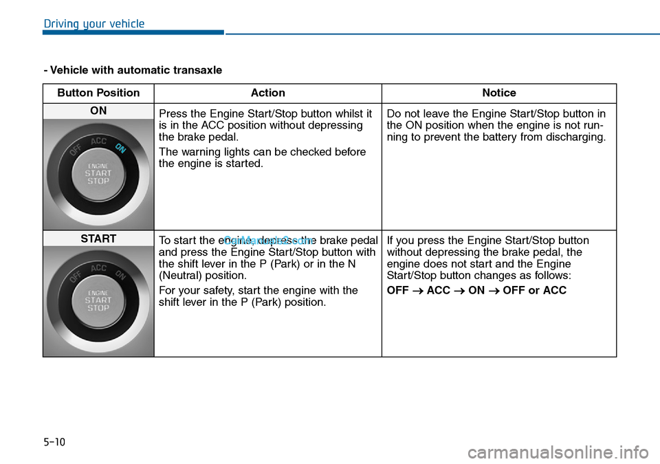
- Vehicle with automatic transaxle
Button Position Action Notice
ON
Press the Engine Start/Stop button whilst it
is in the ACC position without depressing
the brake pedal.
The warning lights can be checked before
the engine is started.Do not leave the Engine Start/Stop button in
the ON position when the engine is not run-
ning to prevent the battery from discharging.
START
To start the engine, depress the brake pedal
and press the Engine Start/Stop button with
the shift lever in the P (Park) or in the N
(Neutral) position.
For your safety, start the engine with the
shift lever in the P (Park) position.If you press the Engine Start/Stop button
without depressing the brake pedal, the
engine does not start and the Engine
Start/Stop button changes as follows:
OFF
→ACC →ON →OFF or ACC
Page 398 of 504
6-7
What to do in an emergency
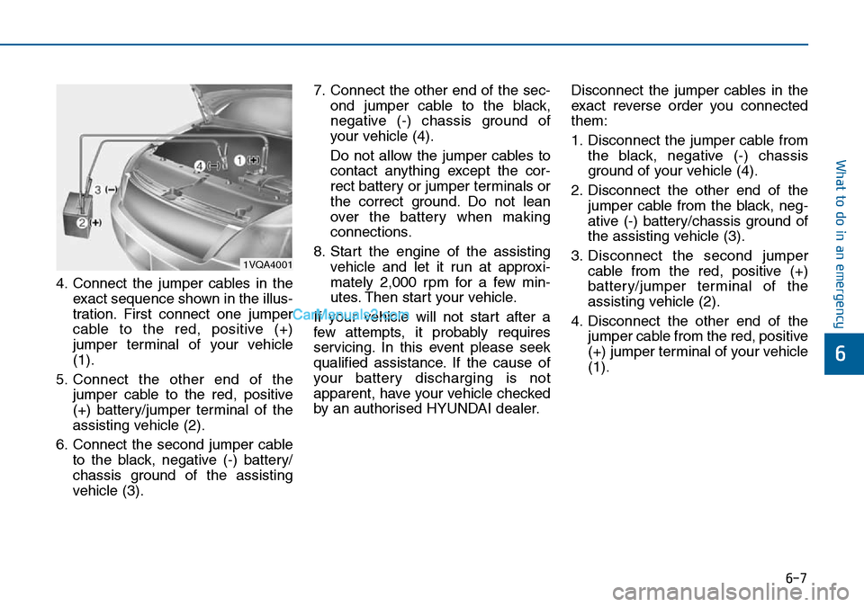
4. Connect the jumper cables in the
exact sequence shown in the illus-
tration. First connect one jumper
cable to the red, positive (+)
jumper terminal of your vehicle
(1).
5. Connect the other end of the
jumper cable to the red, positive
(+) battery/jumper terminal of the
assisting vehicle (2).
6. Connect the second jumper cable
to the black, negative (-) battery/
chassis ground of the assisting
vehicle (3).7. Connect the other end of the sec-
ond jumper cable to the black,
negative (-) chassis ground of
your vehicle (4).
Do not allow the jumper cables to
contact anything except the cor-
rect battery or jumper terminals or
the correct ground. Do not lean
over the battery when making
connections.
8. Start the engine of the assisting
vehicle and let it run at approxi-
mately 2,000 rpm for a few min-
utes. Then start your vehicle.
If your vehicle will not start after a
few attempts, it probably requires
servicing. In this event please seek
qualified assistance. If the cause of
your battery discharging is not
apparent, have your vehicle checked
by an authorised HYUNDAI dealer.Disconnect the jumper cables in the
exact reverse order you connected
them:
1. Disconnect the jumper cable from
the black, negative (-) chassis
ground of your vehicle (4).
2. Disconnect the other end of the
jumper cable from the black, neg-
ative (-) battery/chassis ground of
the assisting vehicle (3).
3. Disconnect the second jumper
cable from the red, positive (+)
battery/jumper terminal of the
assisting vehicle (2).
4. Disconnect the other end of the
jumper cable from the red, positive
(+) jumper terminal of your vehicle
(1).
6
1VQA4001
Page 412 of 504
7
Maintenance
7
Maintenance
Engine compartment .............................................7-3
Maintenance services ...........................................7-5
Owner's responsibility ......................................................7-5
Owner maintenance precautions ..................................7-5
Owner maintenance ...............................................7-6
Owner maintenance schedule ........................................7-7
Scheduled maintenance services.........................7-9
Normal maintenance schedule.....................................7-10
Maintenance under severe usage conditions ..........7-14
Explanation of scheduled maintenance items ..7-16
Engine oil ..............................................................7-20
Checking the engine oil level ....................................7-20
Checking the engine oil and filter ..............................7-21
Engine coolant......................................................7-22
Checking the coolant level ...........................................7-22
Changing the coolant .....................................................7-24
Brake fluid ...........................................................7-25
Checking the brake fluid level .....................................7-25
Washer fluid .........................................................7-27
Checking the washer fluid level ...............................7-27
Parking brake .......................................................7-27
Checking the parking brake .........................................7-27
Air cleaner ............................................................7-28
Filter replacement ...........................................................7-28
Climate control air filter .....................................7-30
Filter inspection ...............................................................7-30
Filter replacement ...........................................................7-30
Wiper blades .........................................................7-31
Blade inspection ..............................................................7-31
Blade replacement ..........................................................7-31
Battery...................................................................7-33
For best battery service................................................7-33
Battery capacity label ...................................................7-34
Battery recharging .......................................................7-35
Reset items .......................................................................7-36
Tyres and wheels .................................................7-37
Tyre care ...........................................................................7-37
Recommended cold tyre inflation pressures ...........7-37
Checking tyre inflation pressure.................................7-39
Tyre rotation ...................................................................7-40
Wheel alignment and tyre balance.............................7-41
Tyre replacement ............................................................7-41
Wheel replacement ........................................................7-43
Tyre traction .....................................................................7-43
Tyre maintenance ..........................................................7-43
Tyre sidewall labelling ....................................................7-43
Low aspect ratio tyre.....................................................7-48
Fuses ......................................................................7-49
Fuse/Relay panel description ......................................7-55
7