low Hyundai Sonata
[x] Cancel search | Manufacturer: HYUNDAI, Model Year: , Model line: , Model:Pages: 208, PDF Size: 16.93 MB
Page 179 of 208
DO-IT-YOURSELF MAINTENANCE 6- 21
G250A01A-AATFOR MORE INFORMATION ABOUT
YOUR HYUNDAI
If you desire additional information about main-
taining and servicing your Hyundai, you may
purchase a factory Shop Manual at your Hyundai
dealer's parts department. This is the same
manual used by dealership technicians and
while it is highly technical it can be useful in
obtaining a better understanding of your car and
how it works.
G240A01A-AATPOWER STEERING HOSES
It is suggested that you check the power steer-
ing hose connections for fluid leakage at regular
intervals. The power steering hoses should be
replaced if there is severe surface cracking,
scuffing or worn spots. Deterioration of the hose
could cause premature failure. Recommended Fluid
Use PSF-3 type fluid
NOTE:Do not start the engine when the power
steering oil reservoir is empty.
G260A02A-AATREPLACING HEADLIGHT BULBS
Before attempting to replace a headlight bulb, be
sure the switch is turned to the "OFF" position.
The next paragraph shows how to reach head-
light bulbs so they may be changed. Be sure to
replace the burned-out bulb with one of the
same number and wattage rating.
!CAUTION:Keep the lamps out of contact with petro-
leum products such as oil, gasoline etc.
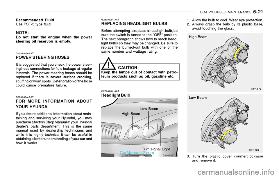
G270A03Y-AAT
Headlight Bulb
1. Allow the bulb to cool. Wear eye protection.
2. Always grasp the bulb by its plastic base,
avoid touching the glass.
G270A03Y
HEF-224
HEF-228
3. Turn the plastic cover counterclockwise
and remove it. High Beam
Low Beam
High BeamLow Beam
Turn signal Light
Page 180 of 208

6- 22 DO-IT-YOURSELF MAINTENANCE
!
4. Disconnect the power cord from the bulb
base in the back of the headlight.
HEF-225
HEF-2291FJB5036HEF-226
HEF-230
WARNING:This halogen bulb contains gas under pres-
sure and if impacted could shatter, result-
ing in flying fragments. Always wear eye
protection when servicing the bulb. Protect
the bulb against abrasions or scratches
and against liquids when lighted. Turn the
bulb on only when installing in a headlight.
Replace the headlight if damaged or cracked.
Keep the bulb out of the reach of children
and dispose of the used bulb with care.
5. Push the bulb spring for removing the head-
light bulb.
High Beam
Low Beam
High Beam
Low Beam
Page 181 of 208
DO-IT-YOURSELF MAINTENANCE 6- 23
HEF-227
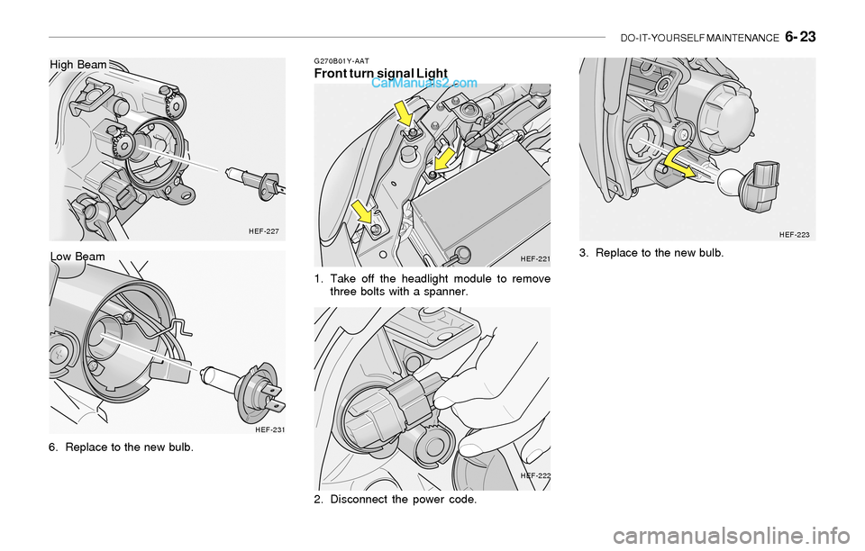
6. Replace to the new bulb.
HEF-231
Low Beam
High BeamG270B01Y-AATFront turn signal Light
1. Take off the headlight module to remove
three bolts with a spanner.
HEF-221
HEF-222HEF-223
2. Disconnect the power code.3. Replace to the new bulb.
Page 184 of 208
6- 26 DO-IT-YOURSELF MAINTENANCE
!
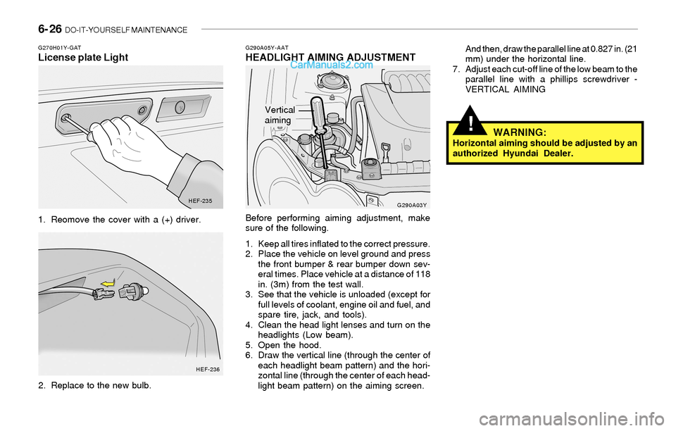
G290A05Y-AATHEADLIGHT AIMING ADJUSTMENT
Before performing aiming adjustment, make
sure of the following.
1. Keep all tires inflated to the correct pressure.
2. Place the vehicle on level ground and press
the front bumper & rear bumper down sev-
eral times. Place vehicle at a distance of 118
in. (3m) from the test wall.
3. See that the vehicle is unloaded (except for
full levels of coolant, engine oil and fuel, and
spare tire, jack, and tools).
4. Clean the head light lenses and turn on the
headlights (Low beam).
5. Open the hood.
6. Draw the vertical line (through the center of
each headlight beam pattern) and the hori-
zontal line (through the center of each head-
light beam pattern) on the aiming screen.And then, draw the parallel line at 0.827 in. (21
mm) under the horizontal line.
7. Adjust each cut-off line of the low beam to the
parallel line with a phillips screwdriver -
VERTICAL AIMING
WARNING:Horizontal aiming should be adjusted by an
authorized Hyundai Dealer.
G290A03Y
G270H01Y-GATLicense plate Light
1. Reomove the cover with a (+) driver.
2. Replace to the new bulb.
HEF-235
HEF-236
Vertical
aiming
Page 185 of 208
DO-IT-YOURSELF MAINTENANCE 6- 27
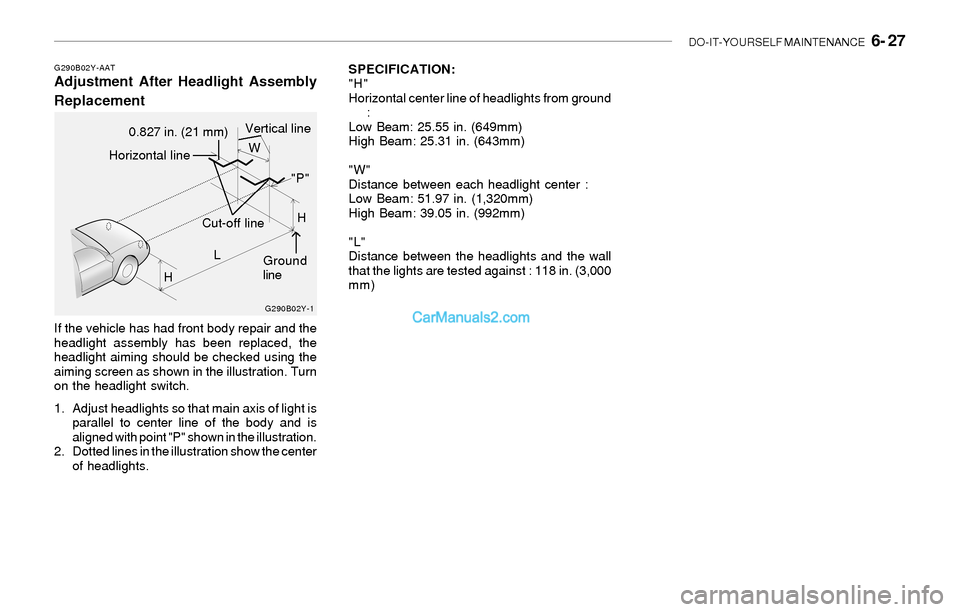
SPECIFICATION:
"H"
Horizontal center line of headlights from ground
:
Low Beam: 25.55 in. (649mm)
High Beam: 25.31 in. (643mm)
"W"
Distance between each headlight center :
Low Beam: 51.97 in. (1,320mm)
High Beam: 39.05 in. (992mm)
"L"
Distance between the headlights and the wall
that the lights are tested against : 118 in. (3,000
mm)G290B02Y-AATAdjustment After Headlight Assembly
Replacement
If the vehicle has had front body repair and the
headlight assembly has been replaced, the
headlight aiming should be checked using the
aiming screen as shown in the illustration. Turn
on the headlight switch.
1. Adjust headlights so that main axis of light is
parallel to center line of the body and is
aligned with point "P" shown in the illustration.
2. Dotted lines in the illustration show the center
of headlights.
G290B02Y-1
LW
H
HCut-off line
Ground
line
"P"
Horizontal line
0.827 in. (21 mm)Vertical line
Page 186 of 208
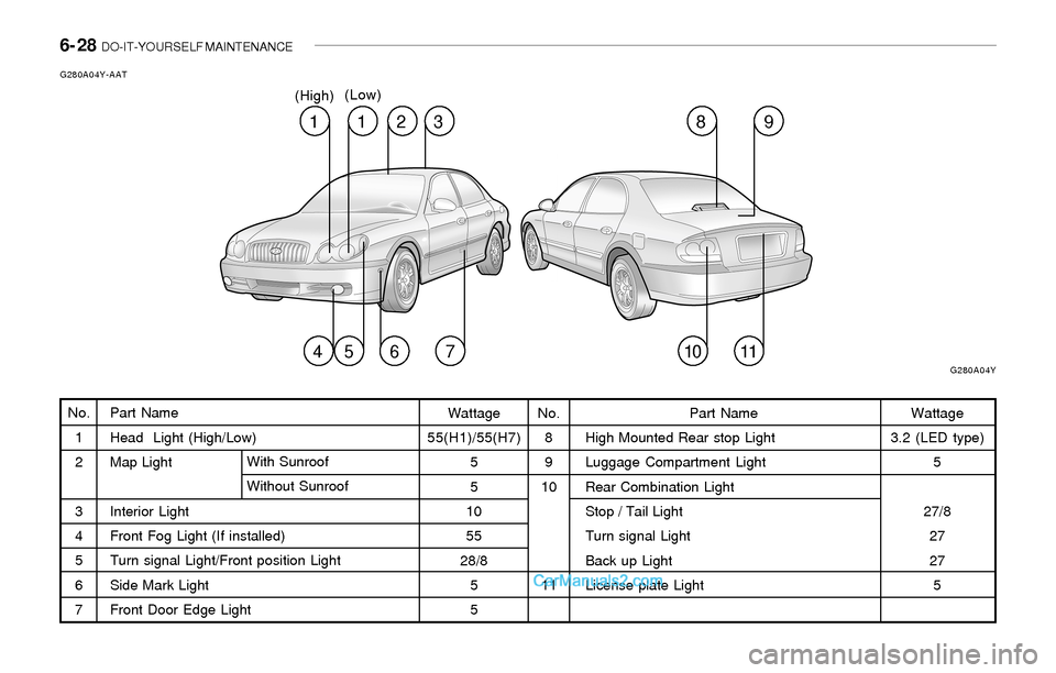
6- 28 DO-IT-YOURSELF MAINTENANCE
Part Name
Head Light (High/Low)
Map Light
Interior Light
Front Fog Light (If installed)
Turn signal Light/Front position Light
Side Mark Light
Front Door Edge LightWith Sunroof
Without Sunroof
G280A04Y-AAT
No.
1
2
3
4
5
6
7Wattage
55(H1)/55(H7)
5
5
10
55
28/8
5
5No.
8
9
10
11Wattage
3.2 (LED type)
5
27/8
27
27
5 Part Name
High Mounted Rear stop Light
Luggage Compartment Light
Rear Combination Light
Stop / Tail Light
Turn signal Light
Back up Light
License plate Light
1
G280A04Y
12389
45671011
(High)(Low)
Page 187 of 208
DO-IT-YOURSELF MAINTENANCE 6- 29
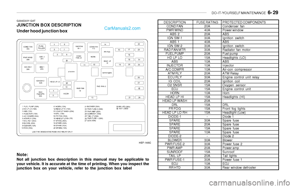
G200C03Y-GATJUNCTION BOX DESCRIPTION
Under hood junction box
Note:
Not all junction box description in this manual may be applicable to
your vehicle. It is accurate at the time of printing. When you inspect the
junction box on your vehicle, refer to the junction box label
DESCRIPTION
COND FAN
PWR WIND
ABS 2
IGN SW-1
ABS 1
IGN SW-2
RAD FAN MTR
FUEL PUMP
HD LP LO
ABS
INJECTOR
A/C COMPR
ATM RLY
ECU RLY
IG COIL
O2 SNSR
ECU
HORN
HEAD LP HI
HEAD LP WASH
DRL
FR FOG
HEAD LP LO RH
DIODE-1
SPARE
SPARE
SPARE
SPARE
DIODE-2
BLOWER
PWR FUSE-2
PWR AMP
SUNROOF
TAIL LP
PWR FUSE-1
ECU
RR HTDFUSE RATING
20A
40A
20A
30A
40A
30A
30A
20A
15A
10A
10A
10A
20A
30A
20A
15A
15A
10A
15A
20A
15A
15A
15A
-
30A
20A
15A
10A
-
30A
30A
20A
15A
20A
30A
10A
30APROTECTED COMPONENTS
Condenser fan
Power window
ABS
Ignition switch
ABS
Ignition switch
Radiator fan motor
Fuel pump
Headlights (LO)
ABS
Injector
Air-con compressor
ATM Relay
Engine control unit relay
Ignition coil
Oxygen sensor
Engine control unit
Horn
Headlights (HI)
-
DRL
Front fog lights
Headlight (Low)
Diode 1
Spare fuse
Spare fuse
Spare fuse
Spare fuse
Diode 2
Blower
Power fuse 2
Power amp
Sunroof
Tail lights
Power fuse 1
ECU
Rear window defroster
HEF-165C
Page 190 of 208
7- 2 EMISSION CONTROL SYSTEMS
H010E01Y-AATEGR System (If installed)
This system helps reduce nitrogen oxides by
recirculating a part of the exhaust gas into the
engine, thereby reducing cylinder combustion
temperature, which results in lower output of
oxides of nitrogen.
H010D01A-AAT3. Exhaust Emission Control System
The Exhaust Emission Control System is a
highly effective system which controls exhaust
emissions while maintaining good vehicle
performace.
H010B01A-AAT1. Crankcase Emission Control
System
The positive crankcase ventilation system is
employed to prevent air pollution caused by
blow-by gases being emitted from the crank-
case. This system supplies filtered air to the
crankcase through the air intake hose. Inside
the crankcase, the fresh air mixes with blow-by
gases, which then pass through the PCV valve
and into the induction system.
H010A01L-AATEMISSION CONTROL SYSTEM
Your Hyundai is equipped with an emission
control system to meet all requirements of the
U.S. Environmental Protection Agency or Cali-
fornia Air Resources Board.
There are three emission control systems which
are as follows.
(1) Crankcase emission control system
(2) Evaporative emission control system
(3) Exhaust emission control system
In order to assure the proper function of the
emission control systems, it is recommended
that you have your car inspected and main-
tained by an authorized Hyundai dealer in ac-
cordance with the maintenance schedule in this
manual.
Caution for Inspection and Maintenance
Test (2.7 V6 Vehicle with Traction Control
System)
o To prevent the vehicle from misfiring
during dynamometer testing, discon-
nect the ABS connector located on the
left side of the engine compartment.
o For more information, see shop manual
(BR-67, Wheel Speed Sensor)
H010C02S-AAT
2. Evaporative Emission Control
(Including ORVR: Onboard Refueling
Vapor Recovery) System
The Evaporative Emission Control System is
designed to prevent fuel vapors from escaping
into the atmosphere.
(The ORVR system is designed to allow the
vapors from the fuel tank to be loaded into a
canister while refueling at the gas station, pre-
venting the escape of fuel vapors into the
atmosphere.)
Canister
Fuel vapors generated inside the fuel tank are
absorbed and stored in the onboard canister.
When the engine is running, the fuel vapors
absorbed in the canister are drawn into the
surge tank through the purge control solenoid
valve.
Purge Control Solenoid Valve (PCSV)
The purge control solenoid valve is controlled
by the Engine Control Module (ECM); when the
engine coolant temperature is low during idling,
the PCSV closes so that evaporated fuel is not
taken into the engine. After the engine warms-
up during ordinary driving, the PCSV opens to
introduce evaporated fuel to the engine.
Page 191 of 208

EMISSION CONTROL SYSTEMS 7- 3
!WARNING:o Use unleaded fuel only.
o Maintain the engine in good operating
condition. Extremely high catalytic con-
verter temperatures can result from im-
proper operation of the electrical, igni-
tion or multiport electronic fuel injec-
tion.
o If your engine stalls, pings, knocks, or is
hard to start, have your Hyundai dealer
inspect and repair the problem as soon
as possible.
o Avoid driving with a very low fuel level.
Running out of gasoline may cause the
engine to misfire and result in damage to
the catalytic converter.
o Avoid idling the engine for periods
longer than 10 minutes.
o The vehicle should not be pushed or
pulled to get started. This may cause the
catalytic converter to overheat and cre-
ate a fire hazard.
o Do not touch the catalytic converter or
any other part of the exhaust system
while the catalytic converter is hot. Shut
off the engine, wait for at least one hour
before touching the catalytic converter
or any other part of the exhaust system.
o Remember that your Hyundai dealer is
your best source of assistance.
H020A01A-AATCATALYTIC CONVERTER
All Hyundai vehicles are equipped with a mono-
lith type three-way catalytic converter to re-
duce the carbon monoxide, hydrocarbons and
nitrogen oxides contained in the exhaust gas.
Exhaust gases passing through the catalytic
converter cause it to operate at a very high
temperature. The introduction of large amounts
of unburned gasoline into the exhaust may
cause the catalytic converter to overheat and
create a fire hazard. This risk may be reduced
by observing the following:o Do not stop your Hyundai over any com-
bustible material such as grass, paper,
leaves or rags. These materials might
contact the hot catalytic converter and a
fire might result.
Catalytic Converter
HEF-240
Page 193 of 208

8- 2 CONSUMER INFORMATION & REPORTING SAFETY DEFECTS
I030A04Y-AATRECOMMENDED INFLATION PRES-
SURES
I020A01A-AATTIRE INFORMATION
The tires supplied on your new Hyundai are
chosen to provide the best performance for
normal driving.
I010B01A-AATEngine NumberI010A01L-AATVEHICLE IDENTIFICATION
NUMBER (VIN)
The vehicle identification number (VIN) is the
number used in registering your car and in all
legal matters pertaining to its ownership, etc. It
can be found in three different places on your
car:
1. On the bulkhead between the engine and
passenger compartments.
2. On the left top side of the instrument panel
where it can be seen by looking down through
the windshield.
3. On the lower side of the center pillar outer
panel.The engine number is stamped on the engine
block as shown in the drawing.
The tire label located on the driver's door edge
gives the tire pressures recommended for your
vehicle.
TIRE SIZE
TIRE PRESSURE-COLD, kPa (PSI)
P205/65R15, P205/60R16
T125/70D15, T125/70R15REAR
210(30)
420(60)FRONT
230(33)
420(60) LOAD UP TO
2 PERSONSMAX.VEHICLE
WEIGHT LIMIT
REAR
230(33)
420(60) FRONT
210(30)
420(60)
HEF-173AI010B01Y
I030A02Y