start Hyundai Sonata Hybrid 2012 Owner's Manual
[x] Cancel search | Manufacturer: HYUNDAI, Model Year: 2012, Model line: Sonata Hybrid, Model: Hyundai Sonata Hybrid 2012Pages: 403, PDF Size: 7.86 MB
Page 312 of 403
719
Maintenance
EXPLANATION OF SCHEDULED MAINTENANCE ITEMS
Engine oil and filter
The engine oil and filter should be
changed at the intervals specified in the
maintenance schedule. If the car is being
driven in severe conditions, more fre-
quent oil and filter changes are required.
Drive belts
Inspect all drive belts for evidence of
cuts, cracks, excessive wear or oil satu-
ration and replace if necessary. Drive
belts should be checked periodically for
proper tension and adjusted as neces-
sary.
Fuel filter
A clogged filter can limit the speed at
which the vehicle may be driven, damage
the emission system and cause multiple
issues such as hard starting. If an exces-
sive amount of foreign matter accumu-
lates in the fuel tank, the filter may
require replacement more frequently.
After installing a new filter, run the engine
for several minutes, and check for leaks
at the connections. Fuel filters should be
installed by an authorized HYUNDAI
dealer.
Fuel lines, fuel hoses and con-
nections
Check the fuel lines, fuel hoses and con-
nections for leakage and damage. Have
an authorized HYUNDAI dealer replace
any damaged or leaking parts immedi-
ately.
Vapor hose and fuel filler cap
The vapor hose and fuel filler cap should
be inspected at those intervals specified
in the maintenance schedule. Make sure
that a new vapor hose or fuel filler cap is
correctly replaced.
Vacuum hoses and crankcase
ventilation hoses
Inspect the surface of hoses for evidence
of heat and/or mechanical damage. Hard
and brittle rubber, cracking, tears, cuts,
abrasions, and excessive swelling indi-
cate deterioration. Particular attention
should be paid to examine those hose
surfaces nearest to high heat sources,
such as the exhaust manifold.
Inspect the hose routing to assure that
the hoses do not come in contact with
any heat source, sharp edges or moving
component which might cause heat dam-
age or mechanical wear. Inspect all hose
connections, such as clamps and cou-
plings, to make sure they are secure, and
that no leaks are present. Hoses should
be replaced immediately if there is any
evidence of deterioration or damage.
Page 314 of 403
721
Maintenance
Parking brake
Inspect the parking brake system includ-
ing the parking brake pedal and cables.
Brake discs, pads, calipers and
rotors
Check the pads for excessive wear, discs
for run out and wear, and calipers for fluid
leakage.
Exhaust pipe and muffler
Visually inspect the exhaust pipes, muf-
fler and hangers for cracks, deterioration,
or damage. Start the engine and listen
carefully for any exhaust gas leakage.
Tighten connections or replace parts as
necessary.
Suspension mounting bolts
Check the suspension connections for
looseness or damage. Retighten to the
specified torque.
Steering gear box, linkage &
boots/lower arm ball joint
With the vehicle stopped and engine off,
check for excessive free-play in the
steering wheel.
Check the linkage for bends or damage.
Check the dust boots and ball joints for
deterioration, cracks, or damage.
Replace any damaged parts.
Drive shafts and boots
Check the drive shafts, boots and clamps
for cracks, deterioration, or damage.
Replace any damaged parts and, if nec-
essary, repack the grease.
Air conditioning refrigerant
Check the air conditioning lines and con-
nections for leakage and damage.
Page 315 of 403
Maintenance
22
7
ENGINE OIL
WARNING - Radiator hose
Be very careful not to touch the
radiator hose when checking or
adding the engine oil as it may be
hot enough to burn you.
CAUTION
Do not overfill with engine oil.
Engine damage may result.
CAUTION
Do not spill engine oil, when addingor changing engine oil. If you dropthe engine oil on the engine room,wipe it off immediately.
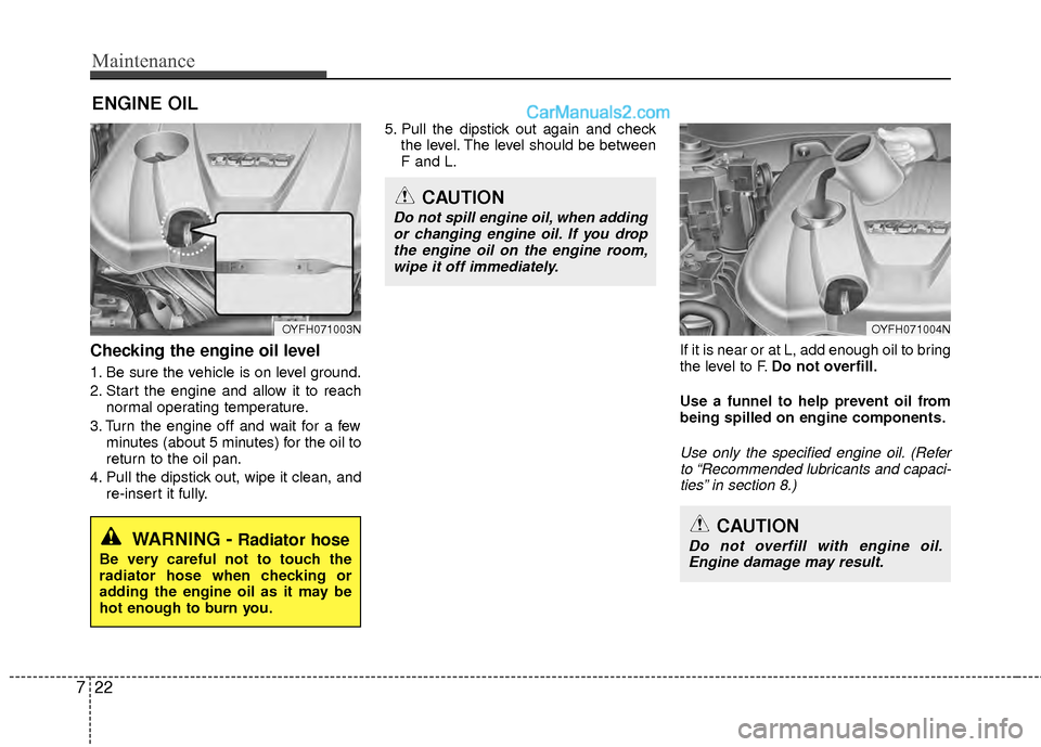
Checking the engine oil level
1. Be sure the vehicle is on level ground.
2. Start the engine and allow it to reach normal operating temperature.
3. Turn the engine off and wait for a few minutes (about 5 minutes) for the oil to
return to the oil pan.
4. Pull the dipstick out, wipe it clean, and re-insert it fully. 5. Pull the dipstick out again and check
the level. The level should be between
F and L.
If it is near or at L, add enough oil to bring
the level to F.Do not overfill.
Use a funnel to help prevent oil from
being spilled on engine components.
Use only the specified engine oil. (Refer to “Recommended lubricants and capaci- ties” in section 8.)
OYFH071003NOYFH071004N
Page 328 of 403
735
Maintenance
Battery recharging
Your vehicle has a maintenance-free,
calcium-based battery.
If the battery becomes discharged in ashort time (because, for example, the
headlights or interior lights were left on
while the vehicle was not in use), jump
start it from another vehicle’s battery or
recharge it by slow charging (trickle)
for 10 hours.
If the battery gradually discharges because of high electric load while the
vehicle is being used, recharge it at 20-
30A for two hours.CALIFORNIA PROPOSI-
TION 65 WARNING
Battery posts, terminals, and relat-
ed accessories contain lead and
lead compounds, chemicals known
to the State of California to cause
cancer, birth defects and reproduc-
tive harm. Batteries also contain
other chemicals known to the State
of California to cause cancer. Wash
hands after handling.
CAUTION
When you don’t use the vehicle
for a long time in the low temper-ature, remove the battery andstore it indoors.
Always charge the battery fully to prevent the battery case dam-aged in low temperatures.
If you connect unauthorized elec- tronic devices to the battery, thebattery may be discharged. Never use unauthorized devices.
(Continued)
When lifting a plastic-cased bat- tery, excessive pressure on the
case may cause battery acid to
leak, resulting in personal injury.
Lift with a battery carrier or with
your hands on opposite corners.
Never attempt to recharge the battery when the battery cables
are connected.
The electrical ignition system works with high voltage. Never
touch these components with the
engine running or the engine
start/stop button positioned on.
Failure to follow the above warn-
ings can result in serious bodily
injury or death.
Page 331 of 403
Maintenance
38
7
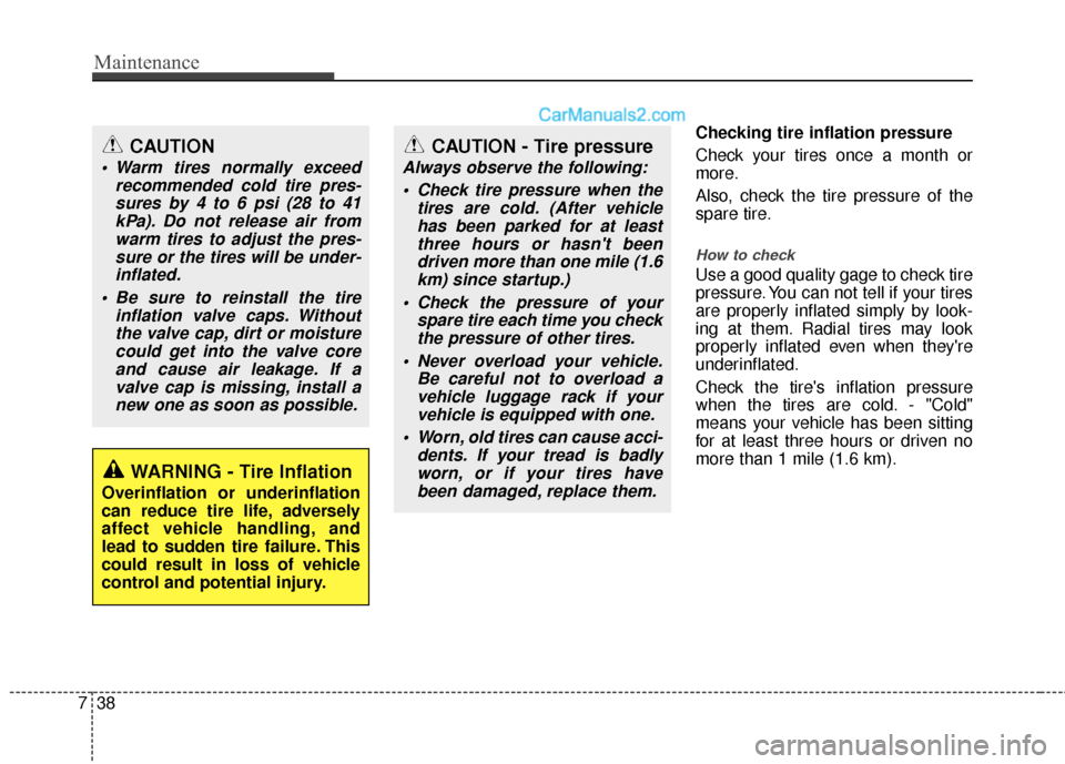
Checking tire inflation pressure
Check your tires once a month or
more.
Also, check the tire pressure of the
spare tire.
How to check
Use a good quality gage to check tire
pressure. You can not tell if your tires
are properly inflated simply by look-
ing at them. Radial tires may look
properly inflated even when they're
underinflated.
Check the tire's inflation pressure
when the tires are cold. - "Cold"
means your vehicle has been sitting
for at least three hours or driven no
more than 1 mile (1.6 km).
WARNING - Tire Inflation
Overinflation or underinflation
can reduce tire life, adversely
affect vehicle handling, and
lead to sudden tire failure. This
could result in loss of vehicle
control and potential injury.
CAUTION - Tire pressure
Always observe the following:
Check tire pressure when the tires are cold. (After vehiclehas been parked for at leastthree hours or hasn't beendriven more than one mile (1.6km) since startup.)
Check the pressure of your spare tire each time you checkthe pressure of other tires.
Never overload your vehicle. Be careful not to overload avehicle luggage rack if yourvehicle is equipped with one.
Worn, old tires can cause acci- dents. If your tread is badlyworn, or if your tires havebeen damaged, replace them.
CAUTION
Warm tires normally exceed recommended cold tire pres-sures by 4 to 6 psi (28 to 41kPa). Do not release air fromwarm tires to adjust the pres-sure or the tires will be under-inflated.
Be sure to reinstall the tire inflation valve caps. Withoutthe valve cap, dirt or moisturecould get into the valve coreand cause air leakage. If avalve cap is missing, install anew one as soon as possible.
Page 344 of 403
751
Maintenance
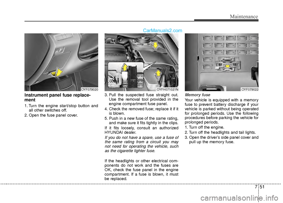
Instrument panel fuse replace-
ment
1. Turn the engine start/stop button andall other switches off.
2. Open the fuse panel cover. 3. Pull the suspected fuse straight out.
Use the removal tool provided in the
engine compartment fuse panel.
4. Check the removed fuse; replace it if it is blown.
5. Push in a new fuse of the same rating, and make sure it fits tightly in the clips.
If it fits loosely, consult an authorized
HYUNDAI dealer.
If you do not have a spare, use a fuse of the same rating from a circuit you maynot need for operating the vehicle, suchas the cigarette lighter fuse.
If the headlights or other electrical com-
ponents do not work and the fuses are
OK, check the fuse panel in the engine
compartment. If a fuse is blown, it must
be replaced.
Memory fuse
Your vehicle is equipped with a memory
fuse to prevent battery discharge if your
vehicle is parked without being operated
for prolonged periods. Use the following
procedures before parking the vehicle for
prolonged periods.
1. Turn off the engine.
2. Turn off the headlights and tail lights.
3. Open the driver’s side panel cover and pull up the memory fuse.
OYF079020OYFH071021NOYF079022
Page 345 of 403
Maintenance
52
7
✽
✽
NOTICE
• If the memory fuse is pulled up from
the fuse panel, the warning chime,
audio, clock and interior lamps, etc.,
will not operate. Some items must be
reset after replacement. Refer to
“Battery” in this section.
• Even though the memory fuse is pulled up, the battery can still be dis-
charged by operation of the head-
lights or other electrical devices.
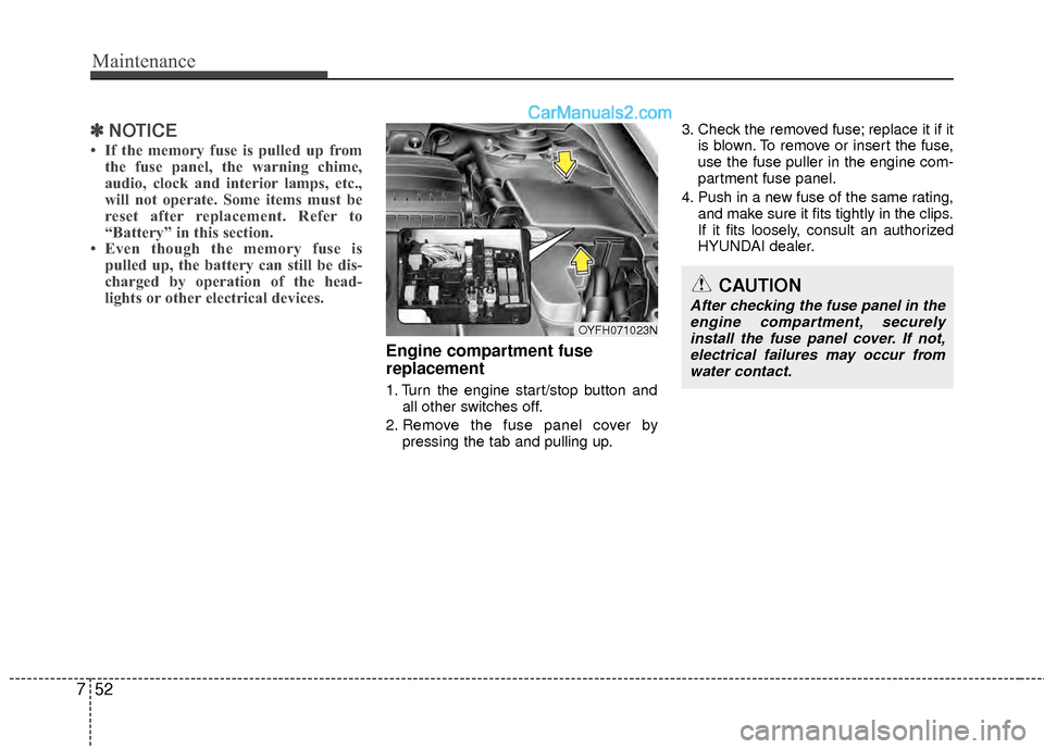
Engine compartment fuse
replacement
1. Turn the engine start/stop button and
all other switches off.
2. Remove the fuse panel cover by pressing the tab and pulling up. 3. Check the removed fuse; replace it if it
is blown. To remove or insert the fuse,
use the fuse puller in the engine com-
partment fuse panel.
4. Push in a new fuse of the same rating, and make sure it fits tightly in the clips.
If it fits loosely, consult an authorized
HYUNDAI dealer.
OYFH071023N
CAUTION
After checking the fuse panel in theengine compartment, securelyinstall the fuse panel cover. If not, electrical failures may occur fromwater contact.
Page 348 of 403
755
Maintenance
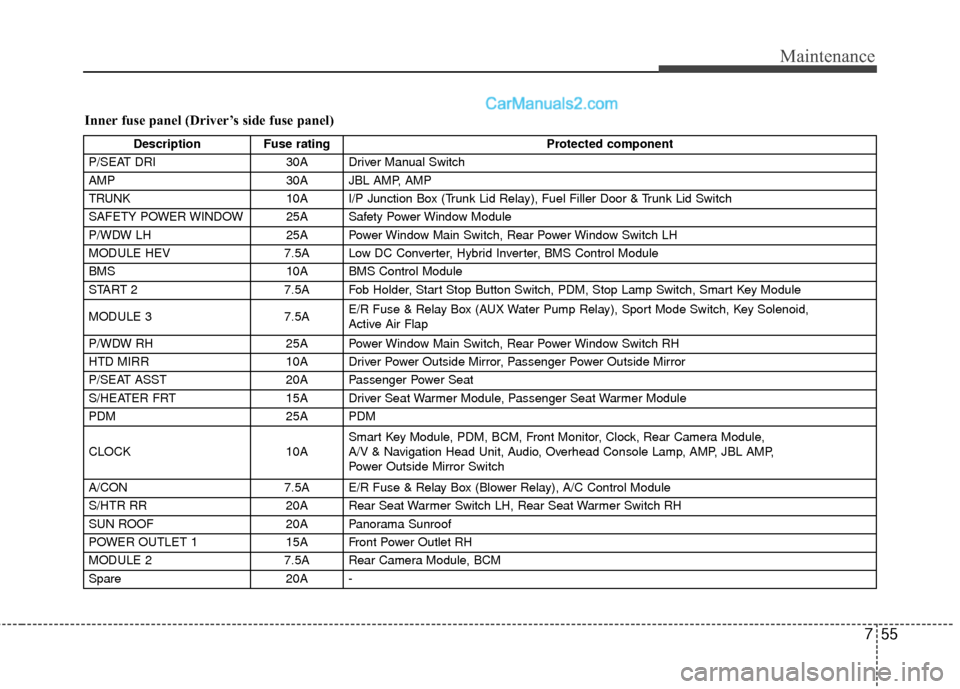
Inner fuse panel (Driver’s side fuse panel)
DescriptionFuse rating Protected component
P/SEAT DRI 30A Driver Manual Switch
AMP 30A JBL AMP, AMP
TRUNK 10A I/P Junction Box (Trunk Lid Relay), Fuel Filler Door & Trunk Lid Switch
SAFETY POWER WINDOW 25A Safety Power Window Module
P/WDW LH 25A Power Window Main Switch, Rear Power Window Switch LH
MODULE HEV 7.5A Low DC Converter, Hybrid Inverter, BMS Control Module
BMS 10A BMS Control Module
START 2 7.5A Fob Holder, Start Stop Button Switch, PDM, Stop Lamp Switch, Smart Key Module
MODULE 3 7.5AE/R Fuse & Relay Box (AUX Water Pump Relay), Sport Mode Switch, Key Solenoid,
Active Air Flap
P/WDW RH 25A Power Window Main Switch, Rear Power Window Switch RH
HTD MIRR 10A Driver Power Outside Mirror, Passenger Power Outside Mirror
P/SEAT ASST 20A Passenger Power Seat
S/HEATER FRT 15A Driver Seat Warmer Module, Passenger Seat Warmer Module
PDM 25A PDM
CLOCK 10ASmart Key Module, PDM, BCM, Front Monitor, Clock, Rear Camera Module,
A/V & Navigation Head Unit, Audio, Overhead Console Lamp, AMP, JBL AMP,
Power Outside Mirror Switch
A/CON 7.5A E/R Fuse & Relay Box (Blower Relay), A/C Control Module
S/HTR RR 20A Rear Seat Warmer Switch LH, Rear Seat Warmer Switch RH
SUN ROOF 20A Panorama Sunroof
POWER OUTLET 1 15A Front Power Outlet RH
MODULE 2 7.5A Rear Camera Module, BCM
Spare 20A -
Page 349 of 403
Maintenance
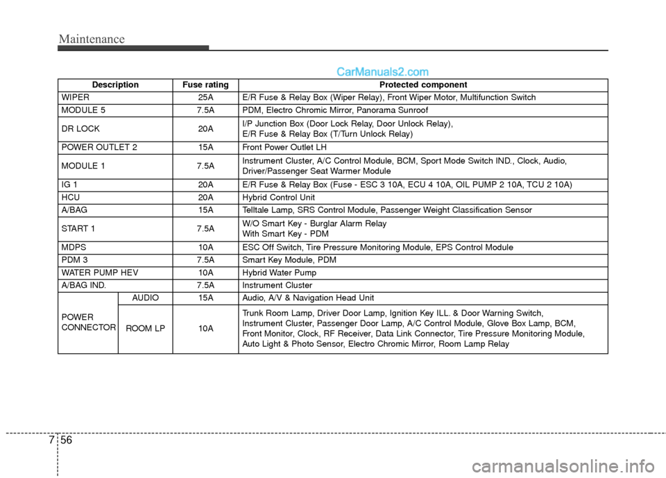
56
7
Description Fuse rating Protected component
WIPER 25A E/R Fuse & Relay Box (Wiper Relay), Front Wiper Motor, Multifunction Switch
MODULE 5 7.5A PDM, Electro Chromic Mirror, Panorama Sunroof
DR LOCK 20AI/P Junction Box (Door Lock Relay, Door Unlock Relay),
E/R Fuse & Relay Box (T/Turn Unlock Relay)
POWER OUTLET 2 15A Front Power Outlet LH
MODULE 1 7.5AInstrument Cluster, A/C Control Module, BCM, Sport Mode Switch IND., Clock, Audio,
Driver/Passenger Seat Warmer Module
IG 1 20A E/R Fuse & Relay Box (Fuse - ESC 3 10A, ECU 4 10A, OIL PUMP 2 10A, TCU 2 10A)
HCU 20A Hybrid Control Unit
A/BAG 15A Telltale Lamp, SRS Control Module, Passenger Weight Classification Sensor
START 1 7.5AW/O Smart Key - Burglar Alarm Relay
With Smart Key - PDM
MDPS 10A ESC Off Switch, Tire Pressure Monitoring Module, EPS Control Module
PDM 3 7.5A Smart Key Module, PDM
WATER PUMP HEV 10A Hybrid Water Pump
A/BAG IND. 7.5A Instrument Cluster
POWER
CONNECTOR AUDIO 15A Audio, A/V & Navigation Head Unit
ROOM LP 10A Trunk Room Lamp, Driver Door Lamp, Ignition Key ILL. & Door Warning Switch,
Instrument Cluster, Passenger Door Lamp, A/C Control Module, Glove Box Lamp, BCM,
Front Monitor, Clock, RF Receiver, Data Link Connector, Tire Pressure Monitoring Module,
Auto Light & Photo Sensor, Electro Chromic Mirror, Room Lamp Relay
Page 350 of 403
757
Maintenance
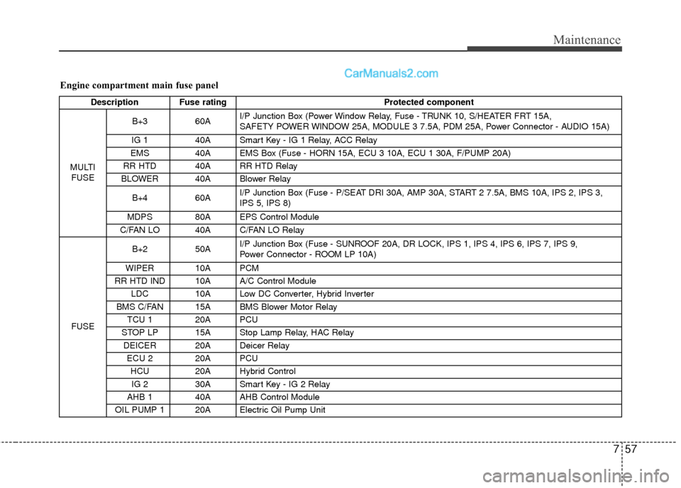
Engine compartment main fuse panel
Description Fuse ratingProtected component
MULTI FUSE B+3
60AI/P Junction Box (Power Window Relay, Fuse - TRUNK 10, S/HEATER FRT 15A,
SAFETY POWER WINDOW 25A, MODULE 3 7.5A, PDM 25A, Power Connector - AUDIO 15A)
IG 1 40A Smart Key - IG 1 Relay, ACC Relay
EMS 40A EMS Box (Fuse - HORN 15A, ECU 3 10A, ECU 1 30A, F/PUMP 20A)
RR HTD 40A RR HTD Relay
BLOWER 40A Blower Relay
B+4 60AI/P Junction Box (Fuse - P/SEAT DRI 30A, AMP 30A, START 2 7.5A, BMS 10A, IPS 2, IPS 3,
IPS 5, IPS 8)
MDPS 80A EPS Control Module
C/FAN LO 40A C/FAN LO Relay
FUSE B+2
50AI/P Junction Box (Fuse - SUNROOF 20A, DR LOCK, IPS 1, IPS 4, IPS 6, IPS 7, IPS 9,
Power Connector - ROOM LP 10A)
WIPER 10A PCM
RR HTD IND 10A A/C Control Module LDC 10A Low DC Converter, Hybrid Inverter
BMS C/FAN 15A BMS Blower Motor Relay TCU 1 20A PCU
STOP LP 15A Stop Lamp Relay, HAC Relay DEICER 20A Deicer Relay ECU 2 20A PCUHCU 20A Hybrid Control
IG 2 30A Smart Key - IG 2 Relay
AHB 1 40A AHB Control Module
OIL PUMP 1 20A Electric Oil Pump Unit