turn signal Hyundai Sonata Hybrid 2013 Owner's Manual
[x] Cancel search | Manufacturer: HYUNDAI, Model Year: 2013, Model line: Sonata Hybrid, Model: Hyundai Sonata Hybrid 2013Pages: 425, PDF Size: 36.95 MB
Page 13 of 425
17
Introduction
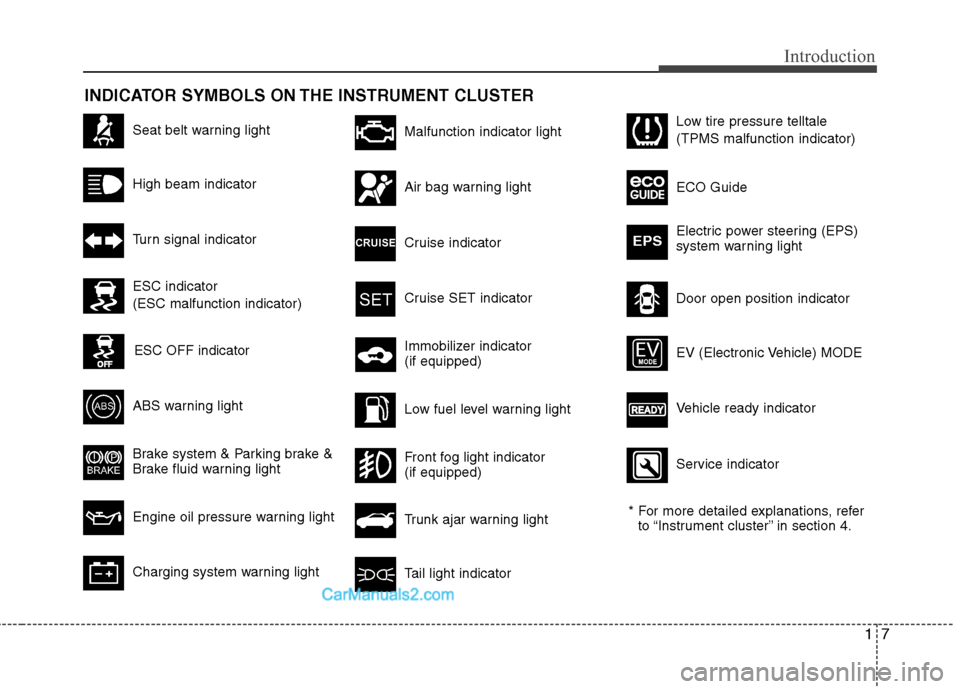
INDICATOR SYMBOLS ON THE INSTRUMENT CLUSTER
Seat belt warning light
High beam indicator
Turn signal indicator
ABS warning light
Brake system & Parking brake &
Brake fluid warning light
Engine oil pressure warning light
Malfunction indicator light
Air bag warning light
Cruise indicator
Cruise SET indicator
Immobilizer indicator
(if equipped)
Low fuel level warning light
* For more detailed explanations, refer
to “Instrument cluster” in section 4.
Charging system warning lightTail light indicator
Trunk ajar warning light
Front fog light indicator
(if equipped)
Door open position indicator Low tire pressure telltale
(TPMS malfunction indicator)
ECO Guide
Electric power steering (EPS)
system warning light
EPS
ESC indicator
(ESC malfunction indicator)
ESC OFF indicator
Vehicle ready indicator EV (Electronic Vehicle) MODE
Service indicator
Page 16 of 425
23
Your vehicle at a glance
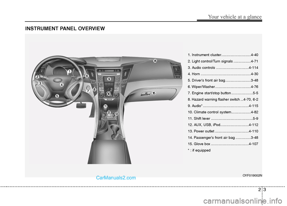
INSTRUMENT PANEL OVERVIEW
OYF019002N
1. Instrument cluster.............................4-40
2. Light control/Turn signals .................4-71
3. Audio controls ................................4-114
4. Horn .................................................4-30
5. Driver’s front air bag .........................3-48
6. Wiper/Washer ...................................4-76
7. Engine start/stop button .....................5-5
8. Hazard warning flasher switch ...4-70, 6-2
9. Audio* .............................................4-115
10. Climate control system ...................4-82
11. Shift lever .........................................5-9
12. AUX, USB, iPod............................4-112
13. Power outlet .................................4-110
14. Passenger’s front air bag ...............3-48
15. Glove box .....................................4-107
* : if equipped
Page 54 of 425
Safety features of your vehicle
36 3
How does the air bag system
operate
Air bags are activated (able to inflate if
necessary) only when the engine
start/stop button is turned to the ON or
START position.
Air bags inflate in the event of serious
frontal or side collision in order to help
protect the occupants from serious
physical injury.
There is no single speed at which the
air bags will inflate.
Generally, air bags are designed to
inflate by the severity of a collision and
its direction. These two factors deter-
mine whether the sensors sendout an
electronic deployment/ inflation signal.
Air bag deployment depends on a
number of factors including vehicle
speed, angles of impact and the densi-
ty and stiffness of the vehicles or
objects which your vehicle hits in the
collision. Though, factors are not limit-
ed to those mentioned above.
The front air bags will completely
inflate and deflate in an instant.
It is virtually impossible for you to see
the air bags inflate during an accident.It is much more likely that you will sim-
ply see the deflated air bags hanging
out of their storage compartments after
the collision.
In order to help provide protection in a
severe collision, the air bags must
inflate rapidly. The speed of air bag
inflation is a consequence of the
extremely short time in which a collision
occurs and the need to get the air bag
between the occupant and the vehicle
structures before the occupant impacts
those structures. This speed of inflation
reduces the risk of serious or life-
threatening injuries in a severe collision
and is thus a necessary part of air bag
design.
However, air bag inflation can also
cause injuries which normally can
include facial abrasions, bruises and
broken bones because the inflation
speed also causes the air bags to
expand with a great deal of force.
There are even circumstances
under which contact with the air bag
can cause fatal injuries, especially if
the occupant is positioned exces-
sively close to the air bag.
WARNING
To avoid severe personal injury
or death caused by deploying air
bags in a collision, the driver
should sit as far back from the
steering wheel air bag as possi-
ble (at least 10 inches (250 mm)
away). The front passengers
should always move their seats
as far back as possible and sit
back in their seat.
Air bags inflate instantly in the
event of collision, and passen-
gers may be injured by the air bag
expansion force if they are not in
proper position.
Air bag inflation may cause
injuries which normally include
facial or bodily abrasions,
injuries from broken glasses or
burns by the air bag inflation
gasses.
Page 115 of 425
435
Features of your vehicle
Programming HomeLink®
✽ ✽
NOTICE
• When programming a garage door
opener, it is advised to park the vehi-
cle outside of the garage.
• It is recommended that a new battery
be placed in the hand-held transmit-
ter of the device being programmed to
HomeLink
®for quicker training and
accurate transmission of the radio-
frequency signal.
• Some vehicles may require the igni-
tion switch to be turned to the second
(or "accessories") position for pro-
gramming and/or operation of
HomeLink.
• In the event that there are still pro-
gramming difficulties or questions
after following the programming steps
listed below, contact HomeLink
®at:
www.homelink.com or 1-800-355-
3515.
Programming
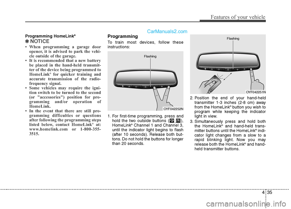
To train most devices, follow these
instructions:
1. For first-time programming, press and
hold the two outside buttons (
,),
HomeLink
®Channel 1 and Channel 3,
until the indicator light begins to flash
(after 10 seconds). Release both but-
tons. Do not hold the buttons for longer
than 20 seconds.2. Position the end of your hand-held
transmitter 1-3 inches (2-8 cm) away
from the HomeLink
®button you wish to
program while keeping the indicator
light in view.
3. Simultaneously press and hold both
the HomeLink
®and hand-held trans-
mitter buttons until the HomeLink®indi-
cator light changes from a slow to a
rapid blinking light. Now you may
release both the HomeLink
®and hand-
held transmitter buttons.
OYF042252N Flashing
OYF042251N Flashing
Page 120 of 425
Features of your vehicle
40 4
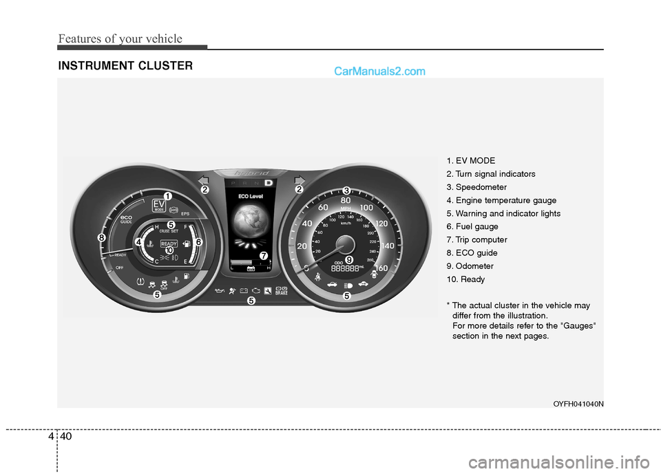
INSTRUMENT CLUSTER
1. EV MODE
2. Turn signal indicators
3. Speedometer
4. Engine temperature gauge
5. Warning and indicator lights
6. Fuel gauge
7. Trip computer
8. ECO guide
9. Odometer
10. Ready
* The actual cluster in the vehicle may
differ from the illustration.
For more details refer to the "Gauges"
section in the next pages.
OYFH041040N
Page 135 of 425
455
Features of your vehicle
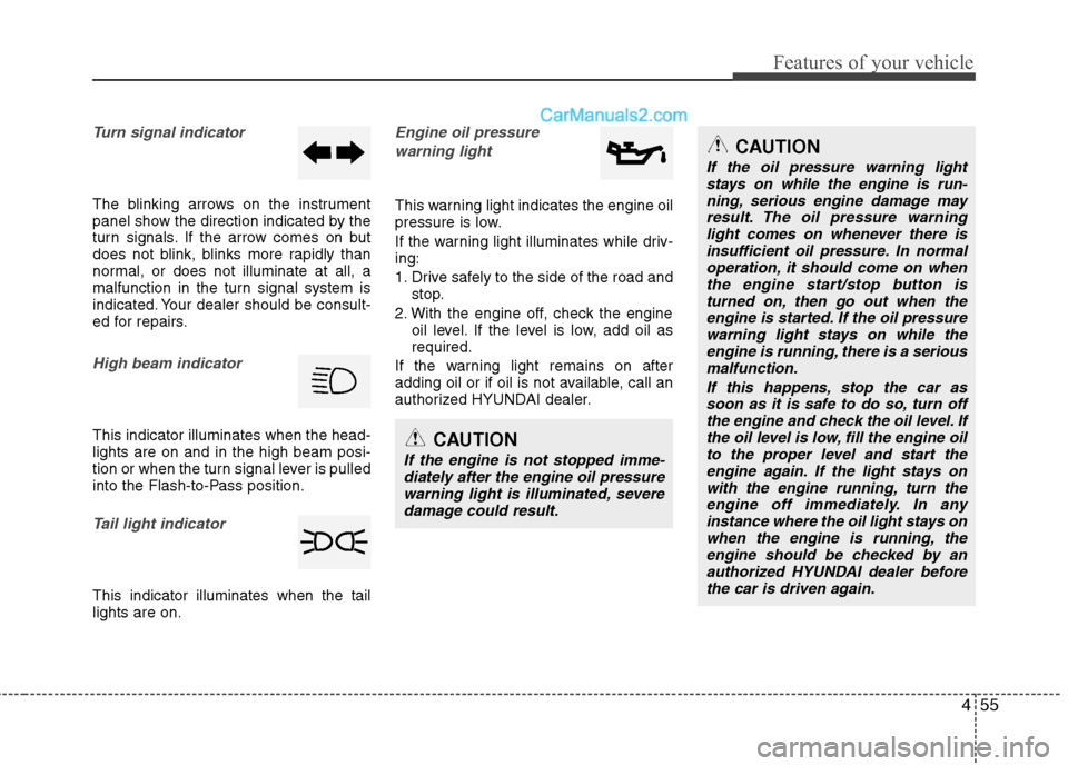
Turn signal indicator
The blinking arrows on the instrument
panel show the direction indicated by the
turn signals. If the arrow comes on but
does not blink, blinks more rapidly than
normal, or does not illuminate at all, a
malfunction in the turn signal system is
indicated. Your dealer should be consult-
ed for repairs.
High beam indicator
This indicator illuminates when the head-
lights are on and in the high beam posi-
tion or when the turn signal lever is pulled
into the Flash-to-Pass position.
Tail light indicator
This indicator illuminates when the tail
lights are on.
Engine oil pressure
warning light
This warning light indicates the engine oil
pressure is low.
If the warning light illuminates while driv-
ing:
1. Drive safely to the side of the road and
stop.
2. With the engine off, check the engine
oil level. If the level is low, add oil as
required.
If the warning light remains on after
adding oil or if oil is not available, call an
authorized HYUNDAI dealer.
CAUTION
If the engine is not stopped imme-
diately after the engine oil pressure
warning light is illuminated, severe
damage could result.
CAUTION
If the oil pressure warning light
stays on while the engine is run-
ning, serious engine damage may
result. The oil pressure warning
light comes on whenever there is
insufficient oil pressure. In normal
operation, it should come on when
the engine start/stop button is
turned on, then go out when the
engine is started. If the oil pressure
warning light stays on while the
engine is running, there is a serious
malfunction.
If this happens, stop the car as
soon as it is safe to do so, turn off
the engine and check the oil level. If
the oil level is low, fill the engine oil
to the proper level and start the
engine again. If the light stays on
with the engine running, turn the
engine off immediately. In any
instance where the oil light stays on
when the engine is running, the
engine should be checked by an
authorized HYUNDAI dealer before
the car is driven again.
Page 150 of 425
Features of your vehicle
70 4
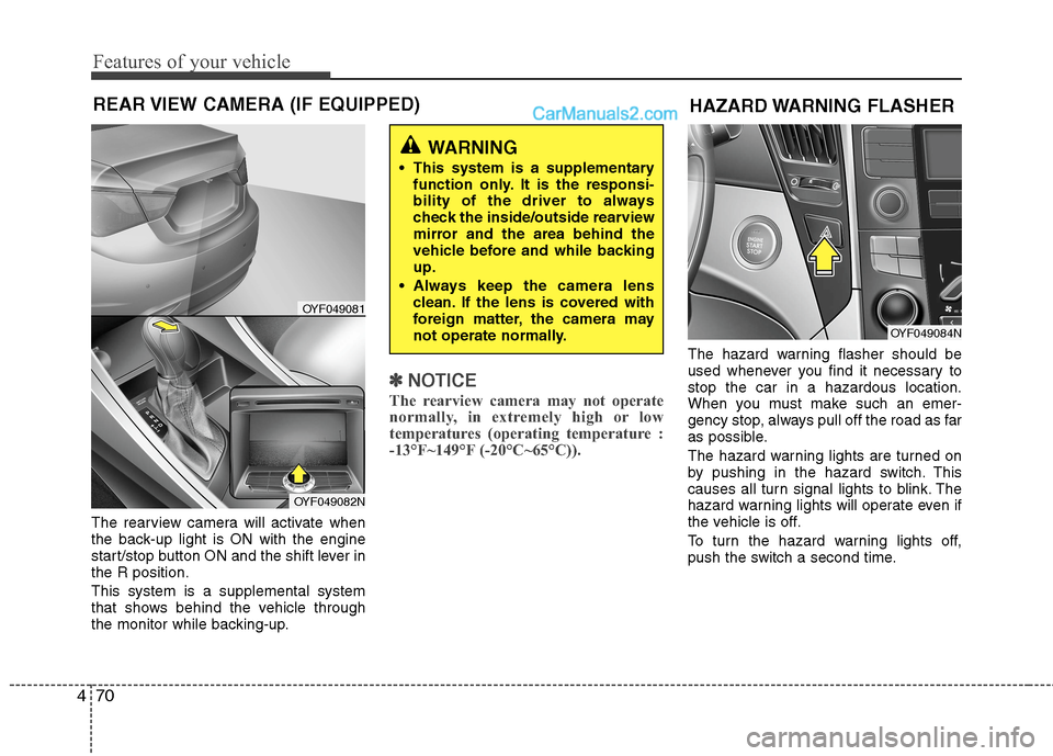
The rearview camera will activate when
the back-up light is ON with the engine
start/stop button ON and the shift lever in
the R position.
This system is a supplemental system
that shows behind the vehicle through
the monitor while backing-up.
✽ ✽
NOTICE
The rearview camera may not operate
normally, in extremely high or low
temperatures (operating temperature :
-13°F~149°F (-20°C~65°C)).
The hazard warning flasher should be
used whenever you find it necessary to
stop the car in a hazardous location.
When you must make such an emer-
gency stop, always pull off the road as far
as possible.
The hazard warning lights are turned on
by pushing in the hazard switch. This
causes all turn signal lights to blink. The
hazard warning lights will operate even if
the vehicle is off.
To turn the hazard warning lights off,
push the switch a second time.
REAR VIEW CAMERA (IF EQUIPPED)
WARNING
This system is a supplementary
function only. It is the responsi-
bility of the driver to always
check the inside/outside rearview
mirror and the area behind the
vehicle before and while backing
up.
Always keep the camera lens
clean. If the lens is covered with
foreign matter, the camera may
not operate normally.
OYF049081
OYF049082N
HAZARD WARNING FLASHER
OYF049084N
Page 154 of 425
Features of your vehicle
74 4
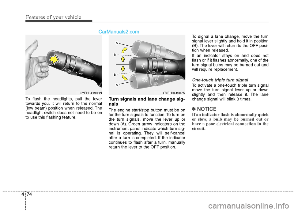
To flash the headlights, pull the lever
towards you. It will return to the normal
(low beam) position when released. The
headlight switch does not need to be on
to use this flashing feature.Turn signals and lane change sig-
nals
The engine start/stop button must be on
for the turn signals to function. To turn on
the turn signals, move the lever up or
down (A). Green arrow indicators on the
instrument panel indicate which turn sig-
nal is operating. They will self-cancel
after a turn is completed. If the indicator
continues to flash after a turn, manually
return the lever to the OFF position.To signal a lane change, move the turn
signal lever slightly and hold it in position
(B). The lever will return to the OFF posi-
tion when released.
If an indicator stays on and does not
flash or if it flashes abnormally, one of the
turn signal bulbs may be burned out and
will require replacement.
One-touch triple turn signal
To activate a one-touch triple turn signal
move the turn signal lever up or down
slightly and then release it. The lane
change signal will blink 3 times.
✽ ✽
NOTICE
If an indicator flash is abnormally quick
or slow, a bulb may be burned out or
have a poor electrical connection in the
circuit.
OYFH041903NOYFH041907N
Page 193 of 425
4113
Features of your vehicle
✽ ✽
NOTICE
If you install an after market HID head
lamp, your vehicle's audio and electron-
ic device may malfunction.
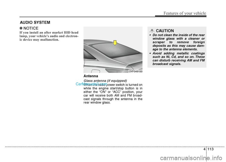
Antenna
Glass antenna (if equipped)
When the radio power switch is turned on
while the engine start/stop button is in
either the “ON” or “ACC” position, your
car will receive both AM and FM broad-
cast signals through the antenna in the
rear window glass.
AUDIO SYSTEM
OYF049150
CAUTION
• Do not clean the inside of the rear
window glass with a cleaner or
scraper to remove foreign
deposits as this may cause dam-
age to the antenna elements.
Avoid adding metallic coatings
such as Ni, Cd, and so on. These
can disturb receiving AM and FM
broadcast signals.
Page 206 of 425
Features of your vehicle
126 4
HD RADIOTMINFORMATION
Licensing information
HD RadioTMTechnology Manufactured
Under License From iBiquity Digital
Corporation. U.S. and Foreign Patents.
HD Radio
TMand the HD and HD Radio
logos are proprietary trademarks of
iBiquity Digital Corporation.
Availability information
HD RadioTM reception is available in the
United States, including Alaska and
Hawaii.
What is HD RadioTMtechnology?
The vehicle audio system (if equipped) is
able to receive standard analog FM/AM
radio broadcasting as well as digital HD
Radio
TMFM/AM broadcasting.
HD RadioTMtechnology provides digital
and analog reception using existing FM
and AM broadcasting frequencies.
Currently, radio stations broadcasting an
HD Radio
TMsignal are operating in a
hybrid mode of both, analog and digital, in
order to reach both receivers. In both
modes, analog and digital, the broadcast-
ed program contents is the same(except
of multicasting, see below).
Eventually, as analog receivers are
replaced by digital ones, radio stations
may be able to turn off their analog broad-
casting and use only digital broadcasting.
Multicasting
HD RadioTMFM stations are able to broad-
cast multiple digital program streams(chan-
nels) over a single FM frequency. For
example, a HD Radio
TMFM station can run
a main channel of music and a sub chan-
nel of news(or even two different music
channels) at one frequency.
But only the program content of the main
channel is broadcasted in analog.
HD RadioTMsignal delay
To overcome the delay that digital sys-
tems inherently produce, HD RadioTM
technology first uses the audio signal of
the analog broadcasting when you tune
to an AM station or to the main channel
of a FM station. After that, the system will
blend from analog to digital signal.
Normally, this blending is very smooth. If
you experience a skip in program content
of several seconds, the radio station has
not implemented HD Radio
TMbroadcast-
ing correctly. This is not a problem with
your audio system.
Due to the fact that sub channels are only
broadcasting digital, blending from ana-
log to digital signal is not possible if you
tune to a sub channel. In this case play-
back of the sub channel starts after sev-
eral seconds, this is a normal function.