ignition Hyundai Sonata Plug-in Hybrid 2017 Owner's Guide
[x] Cancel search | Manufacturer: HYUNDAI, Model Year: 2017, Model line: Sonata Plug-in Hybrid, Model: Hyundai Sonata Plug-in Hybrid 2017Pages: 744, PDF Size: 27.87 MB
Page 355 of 744
4-106
Multimedia System
R
RE
EA
A R
R
V
V I
IE
E W
W
C
C A
A M
M E
ER
R A
A
(
(i if
f
e
e q
q u
u i
ip
p p
pe
ed
d )
)
The system has been equipped
with a rear view camera for user
safety by allowing a wider rear
range of vision.
The rear view camera will automat- ically operate when the ignition key
is turned ON and the shift lever is
set to R (Reverse).
The rear view camera will automat- ically stop operating when shift
lever is set to different position.
B BL
LU
U E
E
L
L I
IN
N K
K®
®(
(I
IF
F
E
E Q
Q U
UI
IP
P P
PE
ED
D )
)
Hyundai aims to offer differentiated
customer values through a
‘Connected Car Life,’ which is to pro-
vide consumers with fast and reliable
IT technology. As consumers’ lifestyles
become more and more mobile in
thanks to remarkable advances in
smart phones, tablet PCs and overall
wireless telecommunication, new
lifestyle patterns demand seamless
connection between one’s office,
home, outdoors and automobiles.
Automobile companies are now faced
with the task of shifting their paradigm
from vehicle-centered services to cus-
tomer value-centered services, with
the ultimate goal of securing global
leadership in the field of vehicle IT and
telematics. Hyundai Motor plans to achieve this
by realizing a terminal platform flexi-
ble to changes in IT technology,
cooperating with global IT compa-
nies, creating an eco-system and
providing the latest contents & servic-
es based on an open environment.
The rear view camera has been
equipped with an optical lens to
provide a wider range of vision
and may appear different from
the actual distance. For safety,
directly check the rear and
left/right sides.
CAUTION
Page 443 of 744
4-194
Multimedia System
R
RE
EA
A R
R
V
V I
IE
E W
W
C
C A
A M
M E
ER
R A
A
(
(i if
f
e
e q
q u
u i
ip
p p
pe
ed
d )
)
The system has been equipped
with a rear view camera for user
safety by allowing a wider rear
range of vision.
The rear view camera will automat- ically operate when the ignition key
is turned ON and the shift lever is
set to R (Reverse).
The rear view camera will automat- ically stop operating when shift
lever is set to different position.
B BL
LU
U E
E
L
L I
IN
N K
K®
®(
(I
IF
F
E
E Q
Q U
UI
IP
P P
PE
ED
D )
)
Hyundai aims to offer differentiated
customer values through a
‘Connected Car Life,’ which is to pro-
vide consumers with fast and reliable
IT technology. As consumers’ lifestyles
become more and more mobile in
thanks to remarkable advances in
smart phones, tablet PCs and overall
wireless telecommunication, new
lifestyle patterns demand seamless
connection between one’s office,
home, outdoors and automobiles.
Automobile companies are now faced
with the task of shifting their paradigm
from vehicle-centered services to cus-
tomer value-centered services, with
the ultimate goal of securing global
leadership in the field of vehicle IT and
telematics. Hyundai Motor plans to achieve this
by realizing a terminal platform flexi-
ble to changes in IT technology,
cooperating with global IT compa-
nies, creating an eco-system and
providing the latest contents & servic-
es based on an open environment.
The rear view camera has been
equipped with an optical lens to
provide a wider range of vision
and may appear different from
the actual distance. For safety,
directly check the rear and
left/right sides.
CAUTION
Page 446 of 744
4-197
Multimedia System
4
zontal line mean?
The horizontal line is adjusted once
per month or at each tank full, based
on your preference; it represents the
EPA combined average or communi-
ty average fuel economy target.
Your actual fuel economy average
over 2.5 minutes.
This value is also shown in bar graph
as your “now” rating.
If you beat the average (the EPA or
community), you will receive an Eco
Reward point.
See your my Hyundai web page for
more information.
[Eco Driving] will not operate if the
vehicle ignition is not turned on.
Please operate with the ignition
turned on.Turn by Turn
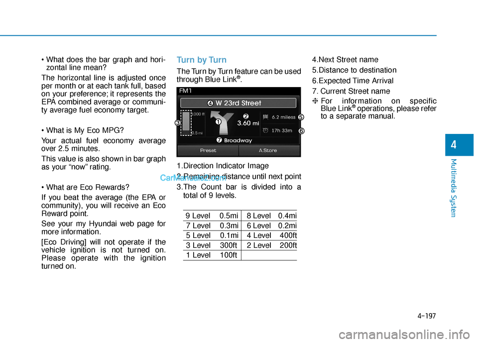
The Turn by Turn feature can be used
through Blue Link®.
1.Direction Indicator Image
2.Remaining distance until next point
3.The Count bar is divided into a total of 9 levels.
9 Level 0.5mi 8 Level 0.4mi
7 Level 0.3mi 6 Level 0.2mi
5 Level 0.1mi 4 Level 400ft
3 Level 300ft 2 Level 200ft
1 Level 100ft 4.Next Street name
5.Distance to destination
6.Expected Time Arrival
7. Current Street name
❈
For information on specific
Blue Link
®operations, please refer
to a separate manual.
Page 451 of 744

5-4
Driving your vehicle
Before entering the vehicle
• Be sure all windows, outside mir-ror(s), and outside lights are clean
and unobstructed.
Remove frost, snow, or ice.
Visually check the tires for uneven wear and damage.
Check under the vehicle for any sign of leaks.
Be sure there are no obstacles behind you if you intend to back up.
Before starting
Make sure the hood, the trunk, andthe doors are securely closed and
locked.
Adjust the position of the seat and steering wheel.
Adjust the inside and outside rearview mirrors.
Verify all the lights work.
Fasten your seatbelt. Check that all passengers have fastened their
seatbelts. Check the gauges and indicators in
the instrument panel and the mes-
sages on the instrument display
when the ignition switch is in the
ON position.
Check that any items you are car- rying are stored properly or fas-
tened down securely.
CALIFORNIA PROPOSITION 65
WARNING
Engine exhaust and a wide vari-
ety of automobile components
including components found in
the interior furnishings in a
vehicle, contain or emit harmful
chemicals known to the State of
California to cause cancer and
birth defects and reproductive
harm. In addition, certain fluids
contained in vehicles and cer-
tain products of components
contain or emit chemicals
known to the State of California
to cause cancer and birth
defects or other reproductive
harm.
WARNING
B B
E
EF
FO
O R
RE
E
D
D R
RI
IV
V I
IN
N G
G
To reduce the risk of SERIOUS
INJURY or DEATH, take the fol-
lowing precautions:
•ALWAYS wear your seat belt.
All passengers must be prop-
erly belted whenever the vehi-
cle is moving. For more infor-
mation, refer to "Seat Belts" in
chapter 2.
Always drive defensively.
Assume other drivers or pedes-
trians may be careless and
make mistakes.
Stay focused on the task of
driving. Driver distraction can
cause accidents.
Leave plenty of space between
you and the vehicle in front of
you.
WARNING
Page 504 of 744
5-57
Driving your vehicle
LDWS Operation
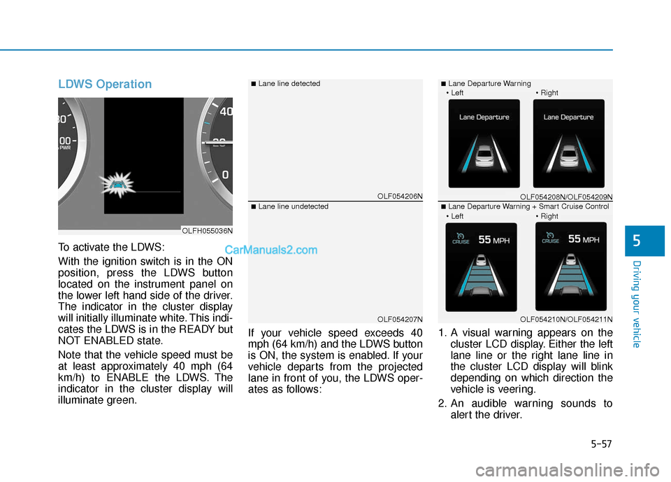
To activate the LDWS:
With the ignition switch is in the ON
position, press the LDWS button
located on the instrument panel on
the lower left hand side of the driver.
The indicator in the cluster display
will initially illuminate white. This indi-
cates the LDWS is in the READY but
NOT ENABLED state.
Note that the vehicle speed must be
at least approximately 40 mph (64
km/h) to ENABLE the LDWS. The
indicator in the cluster display will
illuminate green.If your vehicle speed exceeds 40
mph (64 km/h) and the LDWS button
is ON, the system is enabled. If your
vehicle departs from the projected
lane in front of you, the LDWS oper-
ates as follows:
1. A visual warning appears on the
cluster LCD display. Either the left
lane line or the right lane line in
the cluster LCD display will blink
depending on which direction the
vehicle is veering.
2. An audible warning sounds to alert the driver.5
OLF054206N
OLF054207N
■Lane line detected
■Lane line undetected
OLFH055036N
OLF054208N/OLF054209N
OLF054210N/OLF054211N
■Lane Departure Warning
■Lane Departure Warning + Smart Cruise Control
Page 507 of 744
5-60
Driving your vehicle
Cruise Control operation
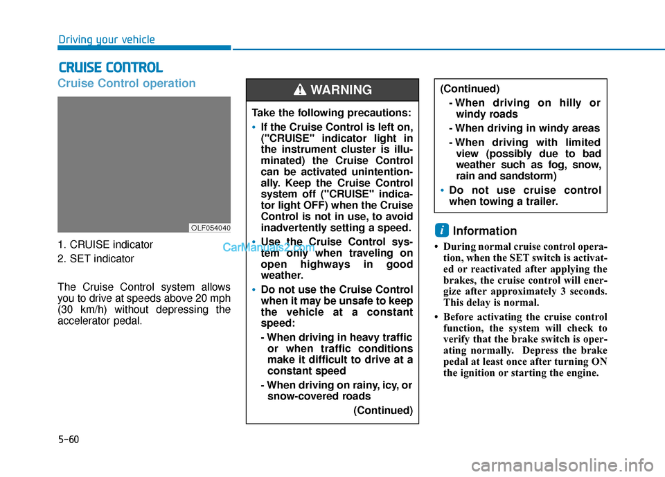
1. CRUISE indicator
2. SET indicator
The Cruise Control system allows
you to drive at speeds above 20 mph
(30 km/h) without depressing the
accelerator pedal.
Information
• During normal cruise control opera-tion, when the SET switch is activat-
ed or reactivated after applying the
brakes, the cruise control will ener-
gize after approximately 3 seconds.
This delay is normal.
• Before activating the cruise control function, the system will check to
verify that the brake switch is oper-
ating normally. Depress the brake
pedal at least once after turning ON
the ignition or starting the engine.
i
C CR
R U
U I
IS
S E
E
C
C O
O N
NT
TR
R O
O L
L
Take the following precautions:
If the Cruise Control is left on,
("CRUISE" indicator light in
the instrument cluster is illu-
minated) the Cruise Control
can be activated unintention-
ally. Keep the Cruise Control
system off ("CRUISE" indica-
tor light OFF) when the Cruise
Control is not in use, to avoid
inadvertently setting a speed.
Use the Cruise Control sys-
tem only when traveling on
open highways in good
weather.
Do not use the Cruise Control
when it may be unsafe to keep
the vehicle at a constant
speed:
- When driving in heavy traffic
or when traffic conditions
make it difficult to drive at a
constant speed
- When driving on rainy, icy, or snow-covered roads
(Continued)
(Continued)- When driving on hilly orwindy roads
- When driving in windy areas
- When driving with limited view (possibly due to bad
weather such as fog, snow,
rain and sandstorm)
Do not use cruise control
when towing a trailer.
WARNING
OLF054040
Page 535 of 744
5-88
Driving your vehicle
Check battery and cables
The winter temperature increases
the battery consumption. Inspect
the battery and cables, as speci-
fied in the chapter 7. The battery
charging level can be checked by an
authorized HYUNDAI dealer or in a
service station.
Change to "winter weight" oil if
necessary
In some regions during winter, it is
recommended to use the "winter
weight" oil with lower viscosity. For
further information, refer to the chap-
ter 8. When you are not sure about a
type of winter weight oil, consult an
authorized HYUNDAI dealer. Check spark plugs and ignition
system
Inspect the spark plugs, as speci-
fied in the chapter 7.
If necessary,
replace them. Also check all ignition
wirings and components for any
cracks, wear-out, and damage.
To prevent locks from freezing
To prevent the locks from being
frozen, spray approved de-icing fluid
or glycerin into key holes. When a
lock opening is already covered with
ice, spray approved de-icing fluid
over the ice to remove it. When an
internal part of a lock freezes, try to
thaw it with a heated key. Carefully
use the heated key to avoid an injury. Use approved window washer
anti-freeze solution in system
To prevent the window washer from
being frozen, add authorized window
washer anti-freeze solution, as spec-
ified on the window washer contain-
er. Window washer anti-freeze solu-
tion is available from an authorized
HYUNDAI dealer, and so are the
most vehicle accessory outlets. Do
not use engine coolant or other types
of anti-freeze solution to prevent any
damage to the vehicle paint.
Page 547 of 744
6-5
What to do in an emergency
6
Information
An inappropriately disposedbattery can be harmful to the
environment and human
health. Dispose the battery
according to your local law(s)
or regulations.
To prevent damage to your vehi-
cle:
Only use a 12-volt power supply (battery or jumper system) to
jump start your vehicle.
Do not attempt to jump start your vehicle by push-starting.
Jump starting procedure
1. Position the vehicles close enough that the jumper cables will reach,
but do not allow the vehicles to
touch.
2. Avoid fans or any moving parts in the engine compartment at all
times, even when the vehicles are
turned off.
3. Turn off all electrical devices such as radios, lights, air conditioning,
etc. Put the vehicles in P (Park)
and set the parking brakes. Turn
both vehicles OFF.
Information
Your vehicle has a battery in the trunk
compartment.
i
NOTICE
i
Pb
(Continued)
NEVER attempt to recharge
the battery when the vehicle’s
battery cables are connected
to the battery.
The electrical ignition system
works with high voltage.
NEVER touch these compo-
nents with the engine running
or when the ignition switch is
in the ON position.
Page 553 of 744
6-11
What to do in an emergency
6
Always check the TPMS malfunction
LCD display after replacing one or
more tires or wheels on your vehicle
to ensure that the replacement or
alternate tires and wheels allow the
TPMS to continue to function proper-
ly.
If any of the below happens, have
the system checked by an author-
ized HYUNDAI dealer.
1. The Low Tire Pressure TPMSMalfunction Indicator does not
illuminate for 3 seconds when
the ignition switch is placed to
the ON position or engine is
running.
2. The TPMS Malfunction Indicator remains illuminated after blink-
ing for approximately 1 minute.
3. The Low Tire Pressure LCD dis- play remains illuminatedLow tire pressure
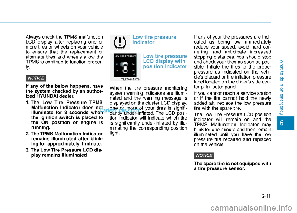
indicator
Low tire pressure
LCD display with
position indicator
When the tire pressure monitoring
system warning indicators are illumi-
nated and the warning message is
displayed on the cluster LCD display,
one or more of your tires is signifi-
cantly under-inflated. The LCD posi-
tion indicator will indicate which tire
is significantly under-inflated by illu-
minating the corresponding position
light. If any of your tire pressures are indi-
cated as being low, immediately
reduce your speed, avoid hard cor-
nering, and anticipate increased
stopping distances. You should stop
and check your tires as soon as pos-
sible. Inflate the tires to the proper
pressure as indicated on the vehi-
cle’s placard or tire inflation pressure
label located on the driver’s side cen-
ter pillar outer panel.
If you cannot reach a service station
or if the tire cannot hold the newly
added air, replace the low pressure
tire with the spare tire.
The Low Tire Pressure LCD position
indicator will remain on and the
TPMS Malfunction Indicator may
blink for one minute and then remain
illuminated until you have the low
pressure tire repaired and replaced
on the vehicle.
The spare tire is not equipped with
a tire pressure sensor.
NOTICE
NOTICEOLF044147N
Page 561 of 744
6-19
What to do in an emergency
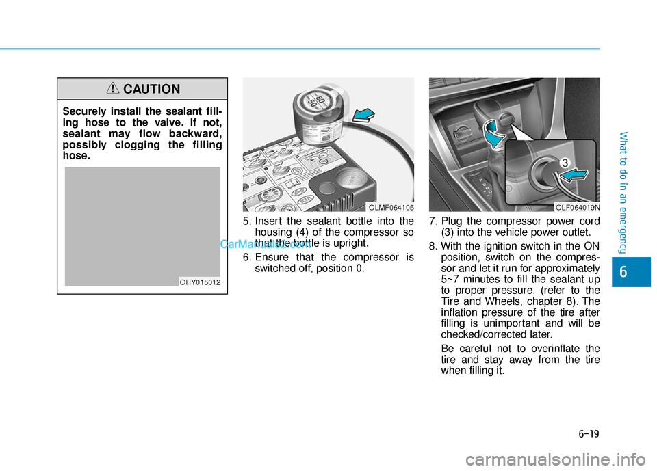
5. Insert the sealant bottle into thehousing (4) of the compressor so
that the bottle is upright.
6. Ensure that the compressor is switched off, position 0. 7. Plug the compressor power cord
(3) into the vehicle power outlet.
8. With the ignition switch in the ON position, switch on the compres-
sor and let it run for approximately
5~7 minutes to fill the sealant up
to proper pressure. (refer to the
Tire and Wheels, chapter 8). The
inflation pressure of the tire after
filling is unimportant and will be
checked/corrected later.
Be careful not to overinflate the
tire and stay away from the tire
when filling it.
6
OLMF064105OLF064019N
Securely install the sealant fill-
ing hose to the valve. If not,
sealant may flow backward,
possibly clogging the filling
hose.
CAUTION
OHY015012