fuel cap Hyundai Terracan 2003 Owner's Manual
[x] Cancel search | Manufacturer: HYUNDAI, Model Year: 2003, Model line: Terracan, Model: Hyundai Terracan 2003Pages: 349, PDF Size: 4.56 MB
Page 50 of 349
FEATURES OF YOUR HYUNDAI
1- 42
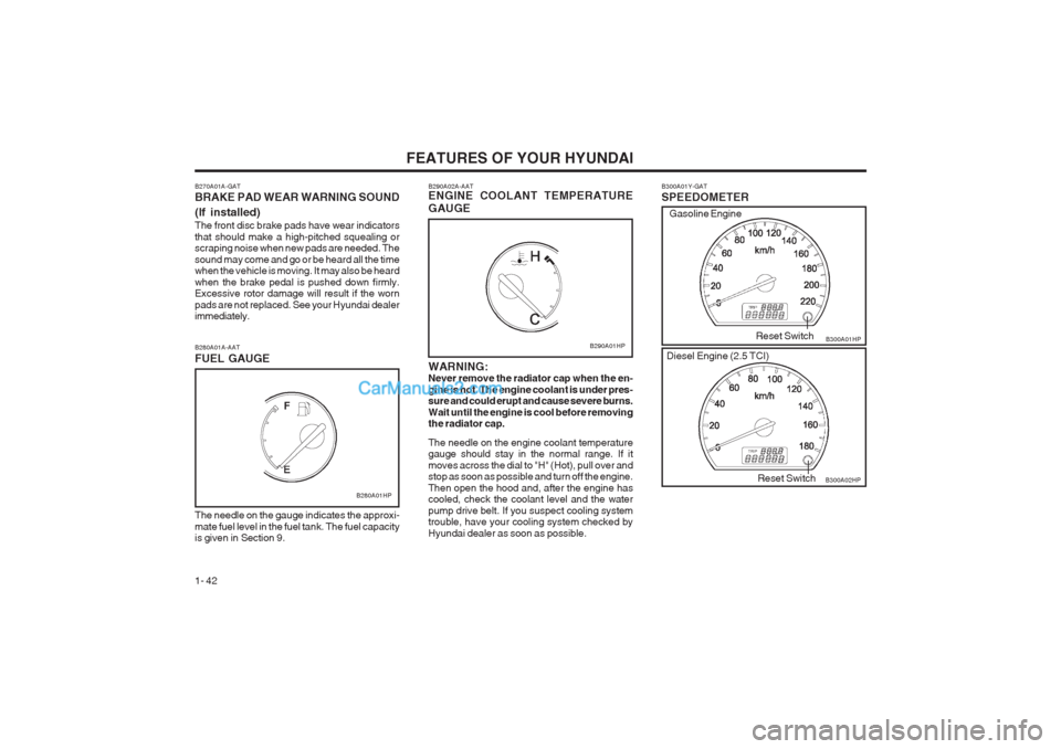
B300A01Y-GAT SPEEDOMETER B300A01HP
B300A02HP
Reset Switch
Reset Switch
Gasoline Engine
Diesel Engine (2.5 TCI)
B280A01A-AAT FUEL GAUGE
B280A01HP
The needle on the gauge indicates the approxi- mate fuel level in the fuel tank. The fuel capacity is given in Section 9. B290A02A-AAT ENGINE COOLANT TEMPERATURE GAUGE WARNING: Never remove the radiator cap when the en- gine is hot. The engine coolant is under pres- sure and could erupt and cause severe burns. Wait until the engine is cool before removing the radiator cap. The needle on the engine coolant temperature gauge should stay in the normal range. If it moves across the dial to "H" (Hot), pull over and stop as soon as possible and turn off the engine. Then open the hood and, after the engine has cooled, check the coolant level and the water pump drive belt. If you suspect cooling system trouble, have your cooling system checked by Hyundai dealer as soon as possible.
B290A01HP
B270A01A-GAT BRAKE PAD WEAR WARNING SOUND (If installed) The front disc brake pads have wear indicators that should make a high-pitched squealing or scraping noise when new pads are needed. The sound may come and go or be heard all the time when the vehicle is moving. It may also be heard when the brake pedal is pushed down firmly. Excessive rotor damage will result if the worn pads are not replaced. See your Hyundai dealer immediately.
Page 69 of 349
FEATURES OF YOUR HYUNDAI 1- 61
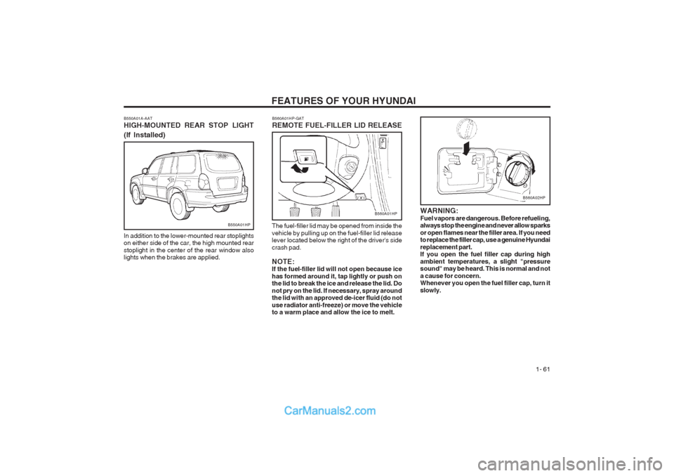
WARNING: Fuel vapors are dangerous. Before refueling, always stop the engine and never allow sparks or open flames near the filler area. If you need to replace the filler cap, use a genuine Hyundai replacement part. If you open the fuel filler cap during high ambient temperatures, a slight "pressure sound" may be heard. This is normal and not a cause for concern. Whenever you open the fuel filler cap, turn it slowly.
B550A01A-AAT HIGH-MOUNTED REAR STOP LIGHT (If Installed)
In addition to the lower-mounted rear stoplights on either side of the car, the high mounted rear stoplight in the center of the rear window also lights when the brakes are applied.
B550A01HP
B560A01HP-GAT REMOTE FUEL-FILLER LID RELEASE
The fuel-filler lid may be opened from inside the vehicle by pulling up on the fuel-filler lid release lever located below the right of the driver's side crash pad. NOTE: If the fuel-filler lid will not open because ice has formed around it, tap lightly or push on the lid to break the ice and release the lid. Do not pry on the lid. If necessary, spray around the lid with an approved de-icer fluid (do not use radiator anti-freeze) or move the vehicle to a warm place and allow the ice to melt.
B560A01HP
B560A02HP
Page 115 of 349
DRIVING YOUR HYUNDAI 2- 9
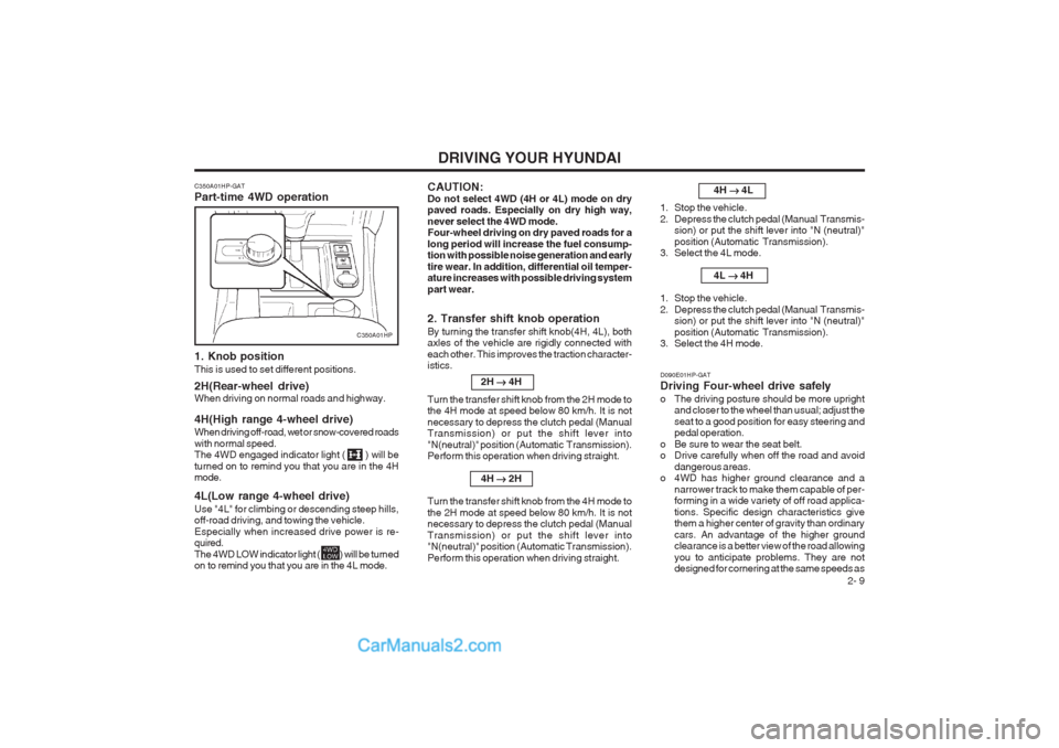
C350A01HP-GAT Part-time 4WD operation
1. Knob position This is used to set different positions. 2H(Rear-wheel drive) When driving on normal roads and highway. 4H(High range 4-wheel drive) When driving off-road, wet or snow-covered roads with normal speed. The 4WD engaged indicator light ( ) will be turned on to remind you that you are in the 4H mode. 4L(Low range 4-wheel drive) Use "4L" for climbing or descending steep hills, off-road driving, and towing the vehicle. Especially when increased drive power is re- quired. The 4WD LOW indicator light ( ) will be turned on to remind you that you are in the 4L mode.
2. Transfer shift knob operation By turning the transfer shift knob(4H, 4L), both axles of the vehicle are rigidly connected with each other. This improves the traction character- istics.2H ��
��
� 4H
Turn the transfer shift knob from the 2H mode tothe 4H mode at speed below 80 km/h. It is not necessary to depress the clutch pedal (Manual Transmission) or put the shift lever into "N(neutral)" position (Automatic Transmission). Perform this operation when driving straight.
4H ��
��
� 2H
Turn the transfer shift knob from the 4H mode to the 2H mode at speed below 80 km/h. It is not necessary to depress the clutch pedal (Manual Transmission) or put the shift lever into "N(neutral)" position (Automatic Transmission). Perform this operation when driving straight.
C350A01HP
D090E01HP-GAT Driving Four-wheel drive safely
o The driving posture should be more uprightand closer to the wheel than usual; adjust the seat to a good position for easy steering and pedal operation.
o Be sure to wear the seat belt.
o Drive carefully when off the road and avoid dangerous areas.
o 4WD has higher ground clearance and a
narrower track to make them capable of per-forming in a wide variety of off road applica- tions. Specific design characteristics give them a higher center of gravity than ordinary cars. An advantage of the higher ground clearance is a better view of the road allowing you to anticipate problems. They are not designed for cornering at the same speeds as 4H
��
��
� 4L
1. Stop the vehicle.
2. Depress the clutch pedal (Manual Transmis- sion) or put the shift lever into "N (neutral)"position (Automatic Transmission).
3. Select the 4L mode.
4L ��
��
� 4H
1. Stop the vehicle.
2. Depress the clutch pedal (Manual Transmis- sion) or put the shift lever into "N (neutral)"position (Automatic Transmission).
3. Select the 4H mode.
CAUTION: Do not select 4WD (4H or 4L) mode on dry paved roads. Especially on dry high way, never select the 4WD mode. Four-wheel driving on dry paved roads for a long period will increase the fuel consump- tion with possible noise generation and early tire wear. In addition, differential oil temper- ature increases with possible driving system part wear.
Page 140 of 349

VEHICLE MAINTENANCE REQUIREMENTS
5- 2
F030A01A-GAT SCHEDULED MAINTENANCE The following maintenance services must be performed to assure good vehicle control and performance. Keep receipts for all vehi
cle services to protect
your warranty. Where both mileage and time are shown, the frequency of service is determined by whichever occurs first. F030B01HP-GAT R :Replace I : Inspect and, after Inspection, clean, adjust, repair or replace if necessary.
ENGINE CONTROL SYSTEM MAINTENANCE (GASOLINE)
ENGINE OIL AND FILTER See Note (1)DRIVE BELT (ALT, DAMPER, TENSIONER, IDLER)FUEL FILTER (MFI TYPE)FUEL LINES, FUEL HOSES AND CONNECTIONSTIMING BELTVAPOR HOSE AND FUEL FILLER CAPVACUUM AND CRANKCASE VENTILATION HOSESAIR CLEANER FILTERSPARK PLUGSSPARK PLUGS (PLATINUM COATED)
NO. DESCRIPTION
1 2 3 4 5 6 7 8 9 120
96
RRR I I I
R I105
84
R I I I90 72
R I I
R I I
RRR75 60
R I I I I60 48
R I
R I III
R45 36
R I I I
R30 24
R I II I
R I
15 12
R I I IKILOMETERS X 1000 MONTHS
Note: (1) European Community Only - API SG, SG/CD, SH OR SH/CD Except European Community - API SE OR ABOVE In case of Gasoline standard engine as recommended oil (API SE or ABOVE) is difficult to obtain in fieId, following oil recomen ded:
API SD - The engine oil and filter should be changed at every 10,000km or 6 months.
Page 145 of 349
VEHICLE MAINTENANCE REQUIREMENTS 5-7
F060A01A-AAT EXPLANATION OF SCHEDULED MAIN- TENANCE ITEMS F060M01A-AAT o Engine Oil and FilterThe engine oil and filter should be changed at
the intervals specified in the maintenance sched- ule. If the car is being driven in severe condi- tions, more frequent oil and filter changes are required. F060B01A-AAT
o Drive BeltsInspect all drive belts for evidence of cuts, cracks, excessive wear or oil saturation and replace if necessary. Drive belts should be checked periodically for proper tension and adjusted as necessary. F060C01A-AAT
o Fuel Filter A clogged filter can limit the speed at which the vehicle may be driven, damage the emission system and cause hard starting. If an exces- sive amount of foreign matter accumulates in the fuel tank, the filter may require replacement more frequently.After installing a new filter, run the engine for several minutes, and check for leaks at the connections. Fuel filters should be installed by trained technicians.
F060D01A-AAT
o Fuel Lines, Fuel Hoses and Connec-
tions
Check the fuel lines, fuel hoses and connec- tions for leakage and damage. Have a trained technician replace any damaged or leaking parts immediately. F060E01A-AAT
o Timing BeltInspect all parts related to the timing belt for damage and deformation. Replace any dam- aged parts immediately. F060G01A-AAT
o Vapor Hose and Fuel Filler CapThe vapor hose and fuel filler cap should be inspected at those intervals specified in the maintenance schedule. Make sure that a new vapor hose or fuel filler cap is correctly re- placed. F060F01A-AAT
o Vacuum, Crankcase
Ventilation Hoses
Inspect the surface of hoses for evidence ofheat and/or mechanical damage. Hard and brit- tle rubber, cracking, tears, cuts, abrasions, and excessive swelling indicate deterioration. Par- ticular attention should be paid to examine those hose surfaces nearest to high heat sourc- es, such as the exhaust manifold. Inspect the hose routing to assure that thehoses do not come in contact with any heat source, sharp edges or moving component which might cause heat damage or mechanical wear. Inspect all hose connections, such as clamps and couplings, to make sure they are secure, and that no leaks are present. Hoses should be replaced immediately if there is any evidence of deterioration or damage. F060H01A-AAT o Air Cleaner FilterA Genuine Hyundai air cleaner filter is recom- mended when the filter is replaced. F060J01A-AAT o Spark PlugsMake sure to install new spark plugs of the correct heat range. F070C01A-AAT o Engine CoolantThe coolant should be changed at the intervals specified in the maintenance sched- ule. F070D01A-AAT o Manual Transmission OilInspect the manual transmission oil according to the maintenance schedule. NOTE: If the oil level is low, check for possible leaks before adding oil. Do not overfill.
Page 148 of 349
DO-IT-YOURSELF MAINTENANCE
6-2
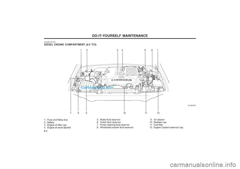
G010B01HP-GAT DIESEL ENGINE COMPARTMENT (2.5 TCI) G010B02HP
1. Fuse and Relay box
2. Battery
3. Engine oil filler cap
4. Engine oil level dipstick 5. Brake fluid reservoir
6 Clutch fluid reservoir
7. Power steering fluid reservoir
8. Windshield washer fluid reservoir
9. Air cleaner
10. Radiator cap
11. Fuel filter
12. Engine Coolant reservoir cap
12 3
4
56
78 9 1 0 11 121
Page 149 of 349
DO-IT-YOURSELF MAINTENANCE 6-3
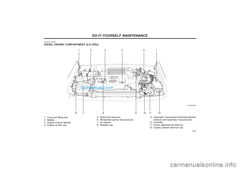
G010C01HP-GAT DIESEL ENGINE COMPARTMENT (2.9 CRDi) G010C02HP
1. Fuse and Relay box
2. Battery
3. Engine oil level dipstick
4. Engine oil filler cap 5. Brake fluid reservoir
6 Windshield washer fluid reservoir
7. Air cleaner
8. Radiator cap
9. Automatic Transmission fluid level dipstick
(Vehicle with Automatic Transmission)
10. Fuel filter
11. Power steering fluid reservoir
12. Engine Coolant reservoir cap
12 3 4
5
6 7 8 9 11 121
10
Page 167 of 349
DO-IT-YOURSELF MAINTENANCE 6-21
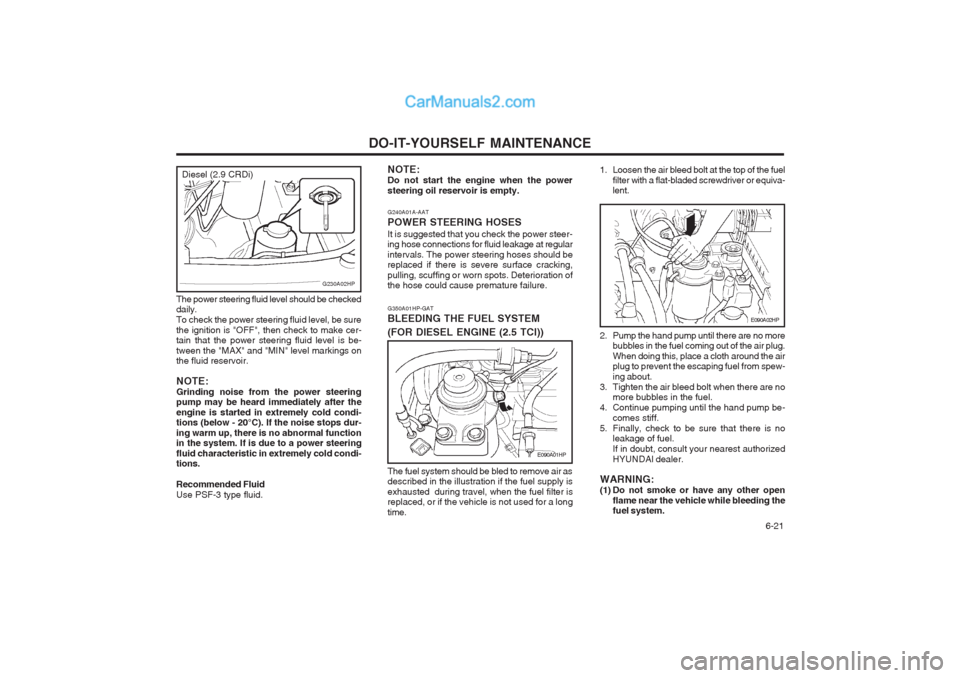
G350A01HP-GAT BLEEDING THE FUEL SYSTEM
(FOR DIESEL ENGINE (2.5 TCI))
E090A01HP
The fuel system should be bled to remove air as described in the illustration if the fuel supply is exhausted during travel, when the fuel filter is replaced, or if the vehicle is not used for a long time.
G240A01A-AAT POWER STEERING HOSESIt is suggested that you check the power steer- ing hose connections for fluid leakage at regular intervals. The power steering hoses should be replaced if there is severe surface cracking, pulling, scuffing or worn spots. Deterioration of the hose could cause premature failure.
NOTE: Do not start the engine when the powersteering oil reservoir is empty.
2. Pump the hand pump until there are no more
bubbles in the fuel coming out of the air plug. When doing this, place a cloth around the air plug to prevent the escaping fuel from spew- ing about.
3. Tighten the air bleed bolt when there are no more bubbles in the fuel.
4. Continue pumping until the hand pump be- comes stiff.
5. Finally, check to be sure that there is no leakage of fuel.If in doubt, consult your nearest authorizedHYUNDAI dealer.
WARNING:
(1) Do not smoke or have any other open flame near the vehicle while bleeding the fuel system.
E090A02HP
1. Loosen the air bleed bolt at the top of the fuel
filter with a flat-bladed screwdriver or equiva- lent.
The power steering fluid level should be checked daily. To check the power steering fluid level, be surethe ignition is "OFF", then check to make cer- tain that the power steering fluid level is be- tween the "MAX" and "MIN" level markings on the fluid reservoir. NOTE: Grinding noise from the power steering pump may be heard immediately after the engine is started in extremely cold condi- tions (below - 20°C). If the noise stops dur- ing warm up, there is no abnormal function in the system. If is due to a power steering fluid characteristic in extremely cold condi- tions. Recommended Fluid Use PSF-3 type fluid.
G230A02HP
Diesel (2.9 CRDi)
Page 169 of 349
DO-IT-YOURSELF MAINTENANCE 6-23
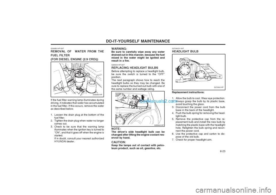
G260A01HP-GAT REPLACING HEADLIGHT BULBSBefore attempting to replace a headlight bulb, be sure the switch is turned to the "OFF" position. The next paragraph shows how to reach theheadlight bulbs so they may be changed. Be sure to replace the burned-out bulb with one of the same number and wattage rating.
WARNING:Be sure to carefully wipe away any waterdrained out in this manner, because the fuel mixed in the water might be ignited and result in a fire. NOTE: The driver's side headlight bulb can be changed after lifting the engine coolant res- ervoir by hand. CAUTION: Keep the lamps out of contact with petro-leum product, such as oil, gasoline, etc.
G260A01HP
Replacement instructions:
1. Allow the bulb to cool. Wear eye protection.
2. Always grasp the bulb by its plastic base,
avoid touching the glass.
3. Disconnect the power cord from the bulb base in the back of the headlight.
4. Push the bulb spring for removing the head-
light bulb.
5. Remove the protective cap from the re- placement bulb and install the new bulb bymatching the plastic base with the headlight hole. Retighten the bulb spring and recon- nect the power cord.
6. Use the protective cap and carton to dis- pose of the old bulb.
7. Check for proper headlight aim. G270A02Y-AAT HEADLIGHT BULB
G270A01HP
G300B01HP-GAT REMOVAL OF WATER FROM THE FUEL FILTER
(FOR DIESEL ENGINE (2.9 CRDi))
G300A01HP
If the fuel filter warning lamp illuminates during driving, it indicates that water has accumulated in the fuel filter. If this occurs, remove the water as described below.
1. Loosen the drain plug at the bottom of the fuel filter.
2. Tighten the drain plug when water no longer
comes out.
3. Check to be sure that the warning lamp illuminates when the ignition key is turned to "ON", and that it goes off when the engine is started. If in doubt, consult your nearest authorizedHYUNDAI dealer.
Page 173 of 349
EMISSION CONTROL SYSTEMS 7-1
7. EMISSION
CONTROL SYSTEMS
H010A01A-GAT EMISSION CONTROL SYSTEMS (If installed) Your Hyundai is equipped with an emission control system to meet all requirements of the Emission prohibition rules of your province. There are three emission control systems which are as follows. (1) Crankcase emission control system (For a Gasoline Engine)
(2) Evaporative emission control system (For a Gasoline Engine)
(3) Exhaust emission control system In order to assure the proper function of the emission control systems, it is recommended that you have your car inspected and main- tained by an authorized Hyundai dealer in ac- cordance with the maintenance schedule in this manual. H010C02Y-GAT 2. Evaporative Emission Control
System; For a Gasoline Engine
The Evaporative Emission Control System is
designed to prevent fuel vapors from escaping into the atmosphere. Canister While the engine is inoperative, fuel vapors
generated inside the fuel tank are absorbed and stored in the canister. When the engine is
running, the fuel vapors absorbed in the canis- ter are drawn into the induction system through the purge control solenoid valve. Purge Control Solenoid Valve The purge control solenoid valve is controlled
by the ECM; when the engine coolant tempera- ture is low, and during idling, it closes, so that evaporated fuel is not taken into the surge tank.
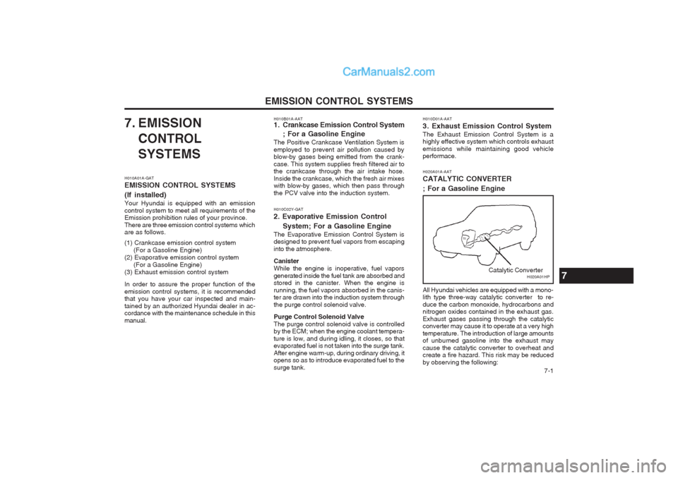
After engine warm-up, during ordinary driving, it opens so as to introduce evaporated fuel to the surge tank. H020A01A-AAT CATALYTIC CONVERTER ; For a Gasoline Engine
H020A01HP
Catalytic Converter
All Hyundai vehicles are equipped with a mono- lith type three-way catalytic converter to re- duce the carbon monoxide, hydrocarbons and nitrogen oxides contained in the exhaust gas. Exhaust gases passing through the catalytic converter may cause it to operate at a very high temperature. The introduction of large amounts of unburned gasoline into the exhaust may cause the catalytic converter to overheat and create a fire hazard. This risk may be reduced by observing the following:
H010B01A-AAT
1. Crankcase Emission Control System
; For a Gasoline Engine
The Positive Crankcase Ventilation System is employed to prevent air pollution caused by blow-by gases being emitted from the crank- case. This system supplies fresh filtered air to the crankcase through the air intake hose. Inside the crankcase, which the fresh air mixes with blow-by gases, which then pass through the PCV valve into the induction system.7
H010D01A-AAT
3. Exhaust Emission Control SystemThe Exhaust Emission Control System is a highly effective system which controls exhaust emissions while maintaining good vehicle performace.