warning lights Hyundai Terracan 2004 Owner's Guide
[x] Cancel search | Manufacturer: HYUNDAI, Model Year: 2004, Model line: Terracan, Model: Hyundai Terracan 2004Pages: 361, PDF Size: 4.69 MB
Page 250 of 361
CONTROLS AND EQUIPMENT
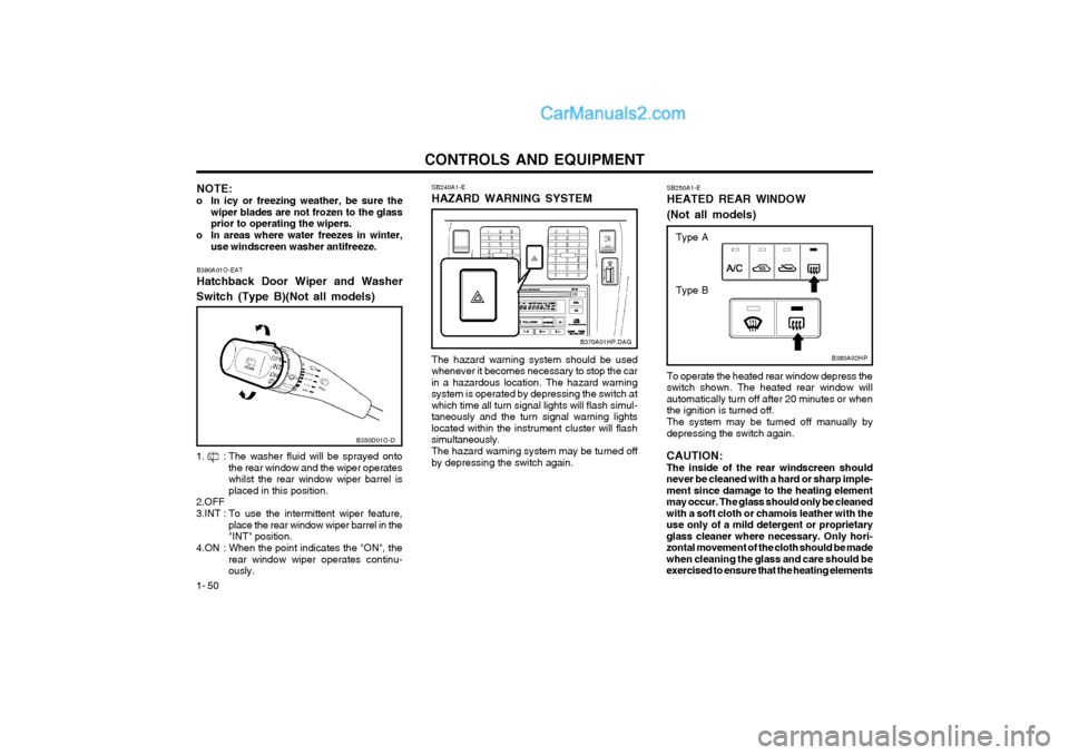
1- 50 SB250A1-E HEATED REAR WINDOW (Not all models)
B380A02HP
To operate the heated rear window depress the switch shown. The heated rear window willautomatically turn off after 20 minutes or whenthe ignition is turned off. The system may be turned off manually by depressing the switch again.
CAUTION:The inside of the rear windscreen shouldnever be cleaned with a hard or sharp imple-ment since damage to the heating elementmay occur. The glass should only be cleanedwith a soft cloth or chamois leather with theuse only of a mild detergent or proprietaryglass cleaner where necessary. Only hori-zontal movement of the cloth should be madewhen cleaning the glass and care should beexercised to ensure that the heating elements Type A
Type B
NOTE:
o In icy or freezing weather, be sure the wiper blades are not frozen to the glass prior to operating the wipers.
o In areas where water freezes in winter, use windscreen washer antifreeze. SB240A1-E HAZARD WARNING SYSTEM
The hazard warning system should be used
whenever it becomes necessary to stop the car in a hazardous location. The hazard warningsystem is operated by depressing the switch atwhich time all turn signal lights will flash simul-taneously and the turn signal warning lightslocated within the instrument cluster will flashsimultaneously.
The hazard warning system may be turned off
by depressing the switch again. B370A01HP.DAG
B390A01O-EAT Hatchback Door Wiper and Washer
Switch (Type B)(Not all models)
1. : The washer fluid will be sprayed onto the rear window and the wiper operates whilst the rear window wiper barrel isplaced in this position.
2.OFF
3.INT : To use the intermittent wiper feature,
place the rear window wiper barrel in the "INT" position.
4.ON : When the point indicates the "ON", the
rear window wiper operates continu-ously. B350D01O-D
Page 253 of 361
CONTROLS AND EQUIPMENT1- 53
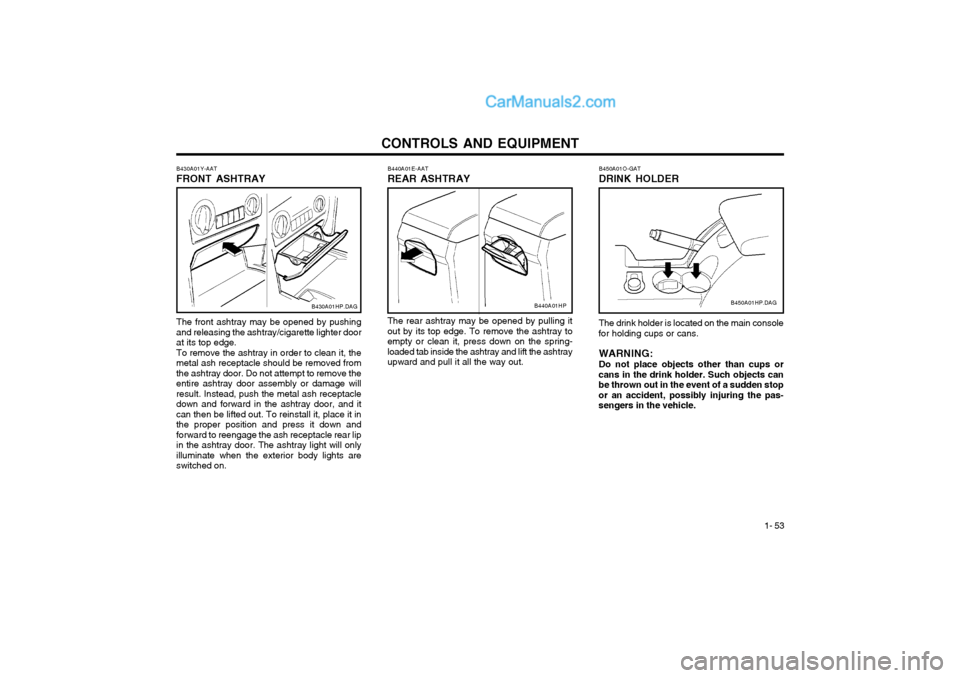
The front ashtray may be opened by pushing and releasing the ashtray/cigarette lighter door at its top edge. To remove the ashtray in order to clean it, the metal ash receptacle should be removed fromthe ashtray door. Do not attempt to remove theentire ashtray door assembly or damage willresult. Instead, push the metal ash receptacledown and forward in the ashtray door, and itcan then be lifted out. To reinstall it, place it inthe proper position and press it down andforward to reengage the ash receptacle rear lipin the ashtray door. The ashtray light will onlyilluminate when the exterior body lights areswitched on.B440A01E-AAT REAR ASHTRAYThe rear ashtray may be opened by pulling it out by its top edge. To remove the ashtray toempty or clean it, press down on the spring-loaded tab inside the ashtray and lift the ashtrayupward and pull it all the way out.
B440A01HP
B430A01Y-AAT FRONT ASHTRAYB430A01HP.DAG
B450A01O-GAT DRINK HOLDER
B450A01HP.DAG
The drink holder is located on the main console
for holding cups or cans.
WARNING: Do not place objects other than cups or
cans in the drink holder. Such objects can be thrown out in the event of a sudden stopor an accident, possibly injuring the pas-sengers in the vehicle.
Page 259 of 361
CONTROLS AND EQUIPMENT1- 59
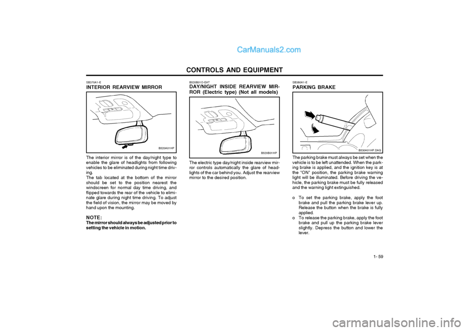
B520B01O-EAT DAY/NIGHT INSIDE REARVIEW MIR- ROR (Electric type) (Not all models) The electric type day/night inside rearview mir-
ror controls automatically the glare of head- lights of the car behind you. Adjust the rearviewmirror to the desired position.
SB370A1-E INTERIOR REARVIEW MIRROR The interior mirror is of the day/night type to
enable the glare of headlights from following vehicles to be eliminated during night time driv-ing.
The tab located at the bottom of the mirror
should be set to the position nearest thewindscreen for normal day time driving, andflipped towards the rear of the vehicle to elimi-nate glare during night time driving. To adjustthe field of vision, the mirror may be moved byhand upon the mounting. NOTE: The mirror should always be adjusted prior tosetting the vehicle in motion.
B520A01HPB520B01HP
SB380A1-E PARKING BRAKE The parking brake must always be set when the
vehicle is to be left unattended. When the park- ing brake is applied, and the ignition key is atthe "ON" position, the parking brake warninglight will be illuminated. Before driving the ve-hicle, the parking brake must be fully releasedand the warning light extinguished.
o To set the parking brake, apply the foot brake and pull the parking brake lever up. Release the button when the brake is fullyapplied.
o To release the parking brake, apply the foot brake and pull up the parking brake leverslightly. Depress the button and lower thelever.
B530A01HP.DAG
Page 262 of 361
CONTROLS AND EQUIPMENT
1- 62
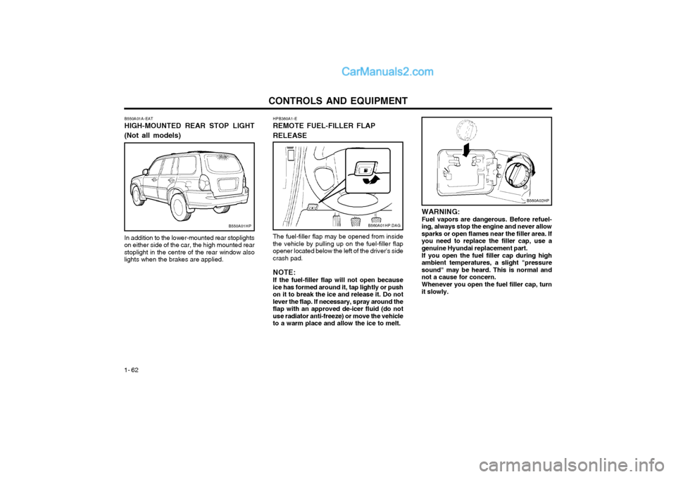
WARNING: Fuel vapors are dangerous. Before refuel-
ing, always stop the engine and never allowsparks or open flames near the filler area. Ifyou need to replace the filler cap, use agenuine Hyundai replacement part.
If you open the fuel filler cap during high
ambient temperatures, a slight "pressuresound" may be heard. This is normal andnot a cause for concern.
Whenever you open the fuel filler cap, turn
it slowly.
The fuel-filler flap may be opened from insidethe vehicle by pulling up on the fuel-filler flapopener located below the left of the driver's sidecrash pad. NOTE: If the fuel-filler flap will not open because ice has formed around it, tap lightly or pushon it to break the ice and release it. Do notlever the flap. If necessary, spray around theflap with an approved de-icer fluid (do notuse radiator anti-freeze) or move the vehicleto a warm place and allow the ice to melt.
HPB360A1-E REMOTE FUEL-FILLER FLAP RELEASE
B560A01HP.DAG
In addition to the lower-mounted rear stoplights on either side of the car, the high mounted rearstoplight in the centre of the rear window alsolights when the brakes are applied.
B550A01A-EAT HIGH-MOUNTED REAR STOP LIGHT (Not all models)B550A01HP
B560A02HP
Page 265 of 361
CONTROLS AND EQUIPMENT1- 65
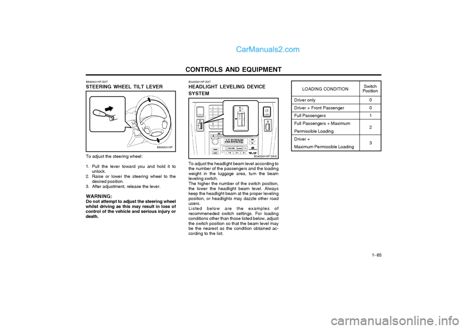
To adjust the steering wheel:
1. Pull the lever toward you and hold it to unlock.
2. Raise or lower the steering wheel to the desired position.
3. After adjustment, release the lever.
WARNING: Do not attempt to adjust the steering wheel
whilst driving as this may result in loss ofcontrol of the vehicle and serious injury ordeath. B600A01HP-EAT STEERING WHEEL TILT LEVER
B600A01HP
Driver only Driver + Front Passenger Full Passengers Full Passengers + Maximum Permissible Loading Driver + Maximum Permissible Loading0 0 1 2 3
LOADING CONDITION
Switch
Position
To adjust the headlight beam level according to
the number of the passengers and the loading weight in the luggage area, turn the beamleveling switch.
The higher the number of the switch position,
the lower the headlight beam level. Alwayskeep the headlight beam at the proper levelingposition, or headlights may dazzle other roadusers.
Listed below are the examples of
recommeneded switch settings. For loadingconditions other than those listed below, adjustthe switch position so that the beam level maybe the nearest as the condition obtained ac-cording to the list. B340G01HP-EAT HEADLIGHT LEVELING DEVICE SYSTEM
B340G01HP.DAG
Page 285 of 361
DRIVING YOUR HYUNDAI
2- 2 C020A01A-EAT
BEFORE STARTING THE ENGINE
Before you start the engine, you should always:
1. Look around the vehicle to be sure there are no flat tyres, puddles of oil or water or other indications of possible trouble.
2. After entering the car, check to be sure the parking brake is engaged.
3. Check that all windows, and lights are clean.
4. Check that the interior and exterior mirrors are clean and in position.
5. Check your seat, seatback and headrest to be sure they are in their proper positions.
6. Close all the doors.
7. Fasten your seat belt and be sure that all other occupants have fastened theirs.
8. Turn off all lights and accessories that are not needed.
9. When you turn the ignition switch to "ON" check that all appropriate warning lights are operating and that you have sufficient fuel.
10.Check the operation of warning lights and all bulbs when key is in the "ON" position. C030A01HP-EAT COMBINATION IGNITION SWITCH AND STEERING LOCK To Start the Engine
o If your Hyundai is equipped with a manual
transmission, place the shift lever in neutral and depress the clutch pedal fully.
o If your Hyundai has an automatic transmis- sion, place the shift lever in "P" (park).
o To start the engine, insert the ignition key and turn it to the "START" position. Releaseit as soon as the engine starts. Do not holdthe key in the "START" position for morethat 15 seconds.
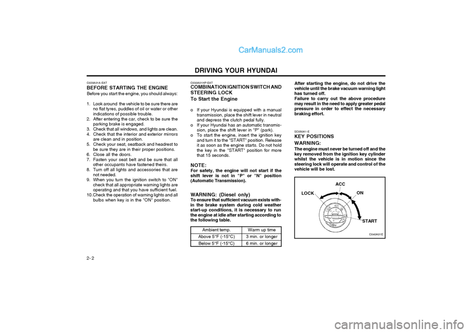
NOTE: For safety, the engine will not start if the shift lever is not in "P" or "N" position(Automatic Transmission). SC050A1-E
KEY POSITIONS WARNING:
The engine must never be turned off and the key removed from the ignition key cylinderwhilst the vehicle is in motion since thesteering lock will operate and control of thevehicle will be lost.
C040A01E
LOCK
ACC
ON
START
WARNING: (Diesel only) To ensure that sufficient vacuum exists with-
in the brake system during cold weatherstart-up conditions, it is necessary to runthe engine at idle after starting according tothe following table.
Ambient temp.
Above 5°F (-15°C) Below 5°F (-15°C)Warm up time
3 min. or longer 6 min. or longer After starting the engine, do not drive the vehicle until the brake vacuum warning lighthas turned off. Failure to carry out the above procedure may result in the need to apply greater pedalpressure in order to effect the necessarybraking effort.
Page 303 of 361
IN CASE OF EMERGENCY 3-1
ZD000A1-A
3. IN CASE OF EMER-
GENCY
D010A01A-EAT
If Engine Stalls Whilst Driving
1. Reduce your speed gradually, keeping a straight line. Move cautiously off the road to a safe place.
2. Turn on your emergency flashers.
3. Try starting the engine again. If your vehicle will not start, contact Hyundai dealer or seek other qualified assistance.
SD020A1-E
IF THE ENGINE WILL NOT START Seek assistance from the nearest Hyundai dealer with regard to the method of ignition and fuelsystem diagnosis.
CAUTION: If the engine refuses to start, no attempt
should be made to push or tow start the vehicle. Vehicles with automatic transmis- sion or fuel injection will not be able to be started in this manner since no drive istransmitted through the automatic trans-mission whilst the engine is not running,and in the case of fuel injected derivatives,the fuel pump will not operate under towstart conditions. In addition, if the vehicle isequipped with an exhaust catalyst, damageto the catalyst may result if the vehicle istow started. HPD020B1-E
IF THE ENGINE CANNOT BE
CRANKED
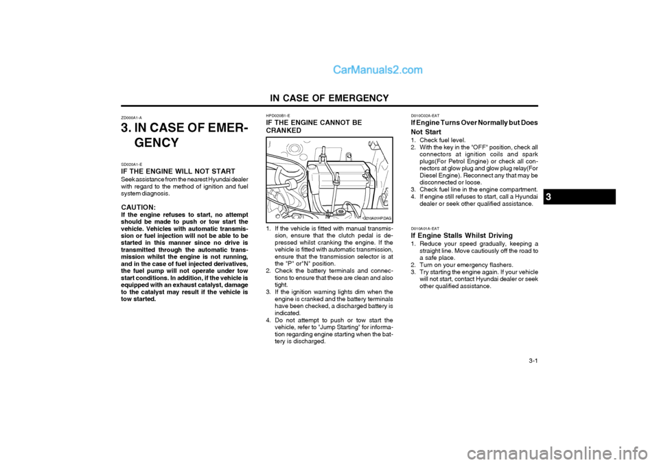
1. If the vehicle is fitted with manual transmis- sion, ensure that the clutch pedal is de-
pressed whilst cranking the engine. If thevehicle is fitted with automatic transmission,ensure that the transmission selector is atthe "P" or"N" position.
2. Check the battery terminals and connec- tions to ensure that these are clean and alsotight.
3. If the ignition warning lights dim when the engine is cranked and the battery terminalshave been checked, a discharged battery isindicated.
4. Do not attempt to push or tow start the vehicle, refer to "Jump Starting" for informa-tion regarding engine starting when the bat-tery is discharged.
G210A01HP.DAG
3
D010C02A-EAT
If Engine Turns Over Normally but Does Not Start
1. Check fuel level.
2. With the key in the "OFF" position, check all connectors at ignition coils and spark plugs(For Petrol Engine) or check all con-nectors at glow plug and glow plug relay(ForDiesel Engine). Reconnect any that may bedisconnected or loose.
3. Check fuel line in the engine compartment.
4. If engine still refuses to start, call a Hyundai dealer or seek other qualified assistance.
Page 304 of 361
IN CASE OF EMERGENCY
3-2
CAUTION:
Personal injury and damage to the vehicle
may occur if jump starting is not performed correctly. If any doubt exists as to how thisoperation should be performed, seek assis-tance from qualified personnel. WARNING:
Motor vehicle batteries contain sulphuric
acid and emit hydrogen gas. Protective cloth- ing should be worn and care exercised toprevent the acid from coming into contactwith skin or clothing and the vehicle. Nakedlights should not be permitted in the vicinityof the battery. Care should be exercised toprevent sparks occurring during connec-tion. If acid accidentally comes into contactwith skin or eyes, the affected area shouldimmediately be flushed with copious CAUTION: If the jump cable is incorrectly installed, damage to the vehicle electrical system mayoccur, in particular the electronic compo-nents such as the Fuel Injection system
computer and the Automatic Transmissioncomputer. The battery must never be dis-connected whilst the engine is running.
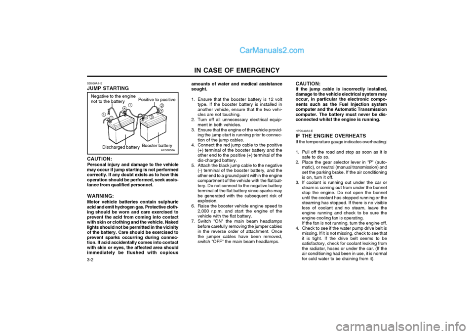
SD030A1-E JUMP STARTING
amounts of water and medical assistance sought.
1. Ensure that the booster battery is 12 volt type. If the booster battery is installed inanother vehicle, ensure that the two vehi-cles are not touching.
2. Turn off all unnecessary electrical equip- ment in both vehicles.
3. Ensure that the engine of the vehicle provid- ing the jump start is running prior to connec-tion of the jump cables.
4. Connect the red jump cable to the positive (+) terminal of the booster battery and theother end to the positive (+) terminal of thedis-charged battery.
5. Attach the black jump cable to the negative (-) terminal of the booster battery, and theother end to a ground point within the enginecompartment of the vehicle with the flat bat-tery. Do not connect to the negative batteryterminal of the flat battery since sparks maybe generated with the subsequent risk ofexplosion.
6. Raise the booster vehicle engine speed to 2,000 r.p.m. and start the engine of thevehicle with the flat battery.
7. Switch "ON" the main beam headlamps before carefully removing the jumper cablesin the reverse order of attachment. Oncethe jumper cables have been removed,switch "OFF" the main beam headlamps. HPD040A2-E IF THE ENGINE OVERHEATS If the temperature gauge indicates overheating:
1. Pull off the road and stop as soon as it is
safe to do so.
2. Place the gear selector lever in "P" (auto- matic), or neutral (manual transmission) and set the parking brake. If the air conditioningis on, turn it off.
3. If coolant is running out under the car or steam is coming out from under the bonnetstop the engine. Do not open the bonnetuntil the coolant has stopped running or thesteaming has stopped. If there is no visibleloss of coolant and no steam, leave theengine running and check to be sure theengine cooling fan is operating. If the fan is not running, turn the engine off.
4. Check to see if the water pump drive belt is missing. If it is not missing, check to see that it is tight. If the drive belt seems to besatisfactory, check for coolant leaking fromthe radiator, hoses or under the car. (If theair conditioning had been in use, it is normalfor cold water to be draining from it).
AX30030A
Negative to the engine not to the battery
Positive to positive
Booster battery
c
e
f d
Discharged battery
Page 342 of 361
OWNER MAINTENANCE
6-18 YG210A1-E
CHECKING ELECTRIC COOLING FANS CAUTION:
The cooling fan is controlled by engine cool- ant temperature and may sometimes oper-ate even when the engine is not running. Donot touch the radiator fan until it is com-pletely stopped. As the coolant temperature decreases the fan will automatically shut off. This is anormal condition.
Checking Engine Cooling Fan The engine cooling fan should automaticallycome on if the engine coolant temperature ishigh.
Checking Condenser Cooling Fan The condenser cooling fan (in front of the con-denser) should come on automatically whenev-er the air conditioner is in operation.
DG210A1-E
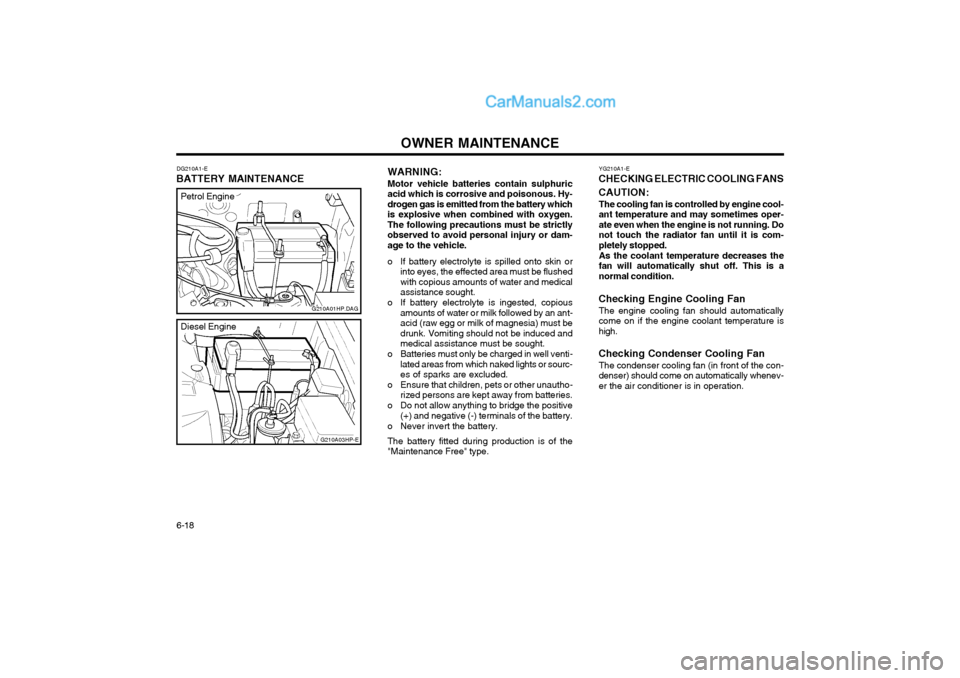
BATTERY MAINTENANCE WARNING:
Motor vehicle batteries contain sulphuricacid which is corrosive and poisonous. Hy-drogen gas is emitted from the battery whichis explosive when combined with oxygen.The following precautions must be strictlyobserved to avoid personal injury or dam-age to the vehicle.
o If battery electrolyte is spilled onto skin or into eyes, the effected area must be flushedwith copious amounts of water and medicalassistance sought.
o If battery electrolyte is ingested, copious amounts of water or milk followed by an ant-acid (raw egg or milk of magnesia) must bedrunk. Vomiting should not be induced andmedical assistance must be sought.
o Batteries must only be charged in well venti- lated areas from which naked lights or sourc-es of sparks are excluded.
o Ensure that children, pets or other unautho- rized persons are kept away from batteries.
o Do not allow anything to bridge the positive (+) and negative (-) terminals of the battery.
o Never invert the battery.
The battery fitted during production is of the"Maintenance Free" type.
G210A01HP.DAG
G210A03HP-E
Petrol Engine
Diesel Engine
Page 359 of 361
INDEX10-3
M Maintenance Requirements
Explanation of scheduled maintenance items ........................ 5-6 ~ 5-8
Maintenance and servicing requirements ....................................... 5-1
Maintenance under severe usage conditions ................................. 5-5
Regular servicing ................................................................... 5-2 ~ 5-4
Mirrors Day/night inside rearview .............................................................. 1-59
Outside rearview ........................................................................... 1-58
Multi Function Switch
Headlight flash .............................................................................. 1-47
High and low beam ....................................................................... 1-47
Lane change signal ....................................................................... 1-46
Lighting switch ............................................................................... 1-47
Sidelight auto cut .......................................................................... 1-47
Turn signal operation .................................................................... 1-46
OOdometer .......................................................................................... 1-45
P Parking Brake ................................................................................... 1-59
Part-time 4WD Operation ......................................................... 2-9 ~ 2-11
Power Driver's Seat .......................................................................... 1-12
Power Outlet ..................................................................................... 1-52
Power Steering Fluid Level ............. ..................................................6-19
I Ignition Switch
..................................................................................... 2-2
Immobiliser System .................................................................... 1-2 ~ 1-4
Key ........................................................................................... 1-2, 1-4
Indicator and Warning Lights ................................................. 1-40 ~ 1-43
Instrument Cluster and Indicator ............................................ 1-32 ~ 1-39
Instruments and Controls ................ ..................................................1-31
Intermittent Wipe Facility ................................................................... 1-49
J Jump Starting ...................................................................................... 3-2
K
Key ............................................................................................... 1-2, 1-4 If you lose your keys .................................................................... 3-11
Positions .......................................................................................... 2-2
LLimited-Slip Differential ..................................................................... 2-14
Luggage Compartment Cargo Security Screen .................................................................. 1-61
Light ............................................................................................... 1-60
Net ................................................................................................. 1-60