mirror controls Hyundai Terracan 2004 Owner's Manual
[x] Cancel search | Manufacturer: HYUNDAI, Model Year: 2004, Model line: Terracan, Model: Hyundai Terracan 2004Pages: 361, PDF Size: 4.69 MB
Page 65 of 361
FEATURES OF YOUR HYUNDAI 1- 57
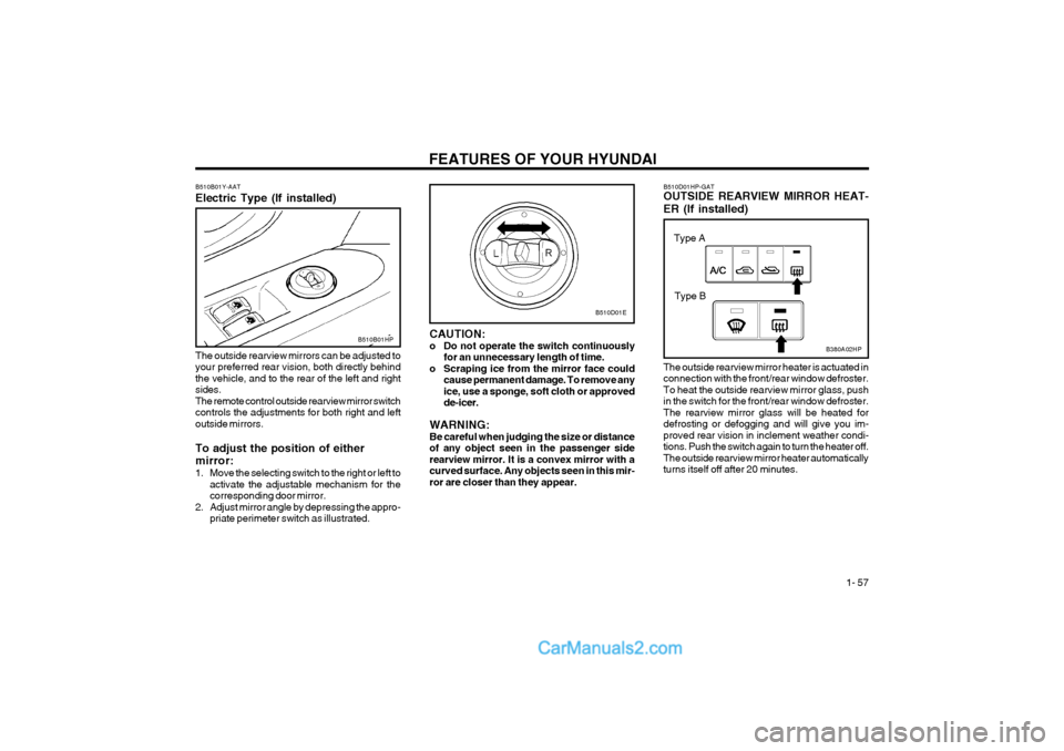
B510D01HP-GAT OUTSIDE REARVIEW MIRROR HEAT- ER (If installed)
B380A02HP
The outside rearview mirror heater is actuated in connection with the front/rear window defroster.To heat the outside rearview mirror glass, pushin the switch for the front/rear window defroster.The rearview mirror glass will be heated fordefrosting or defogging and will give you im-proved rear vision in inclement weather condi-tions. Push the switch again to turn the heater off.The outside rearview mirror heater automaticallyturns itself off after 20 minutes.
B510D01E
CAUTION:
o Do not operate the switch continuously for an unnecessary length of time.
o Scraping ice from the mirror face could cause permanent damage. To remove anyice, use a sponge, soft cloth or approvedde-icer.
WARNING:Be careful when judging the size or distanceof any object seen in the passenger siderearview mirror. It is a convex mirror with acurved surface. Any objects seen in this mir-ror are closer than they appear.
B510B01Y-AAT Electric Type (If installed)
B510B01HP
The outside rearview mirrors can be adjusted to your preferred rear vision, both directly behindthe vehicle, and to the rear of the left and rightsides.The remote control outside rearview mirror switchcontrols the adjustments for both right and leftoutside mirrors. To adjust the position of either mirror:
1. Move the selecting switch to the right or left to activate the adjustable mechanism for the corresponding door mirror.
2. Adjust mirror angle by depressing the appro- priate perimeter switch as illustrated.
Type A
Type B
Page 67 of 361
FEATURES OF YOUR HYUNDAI 1- 59
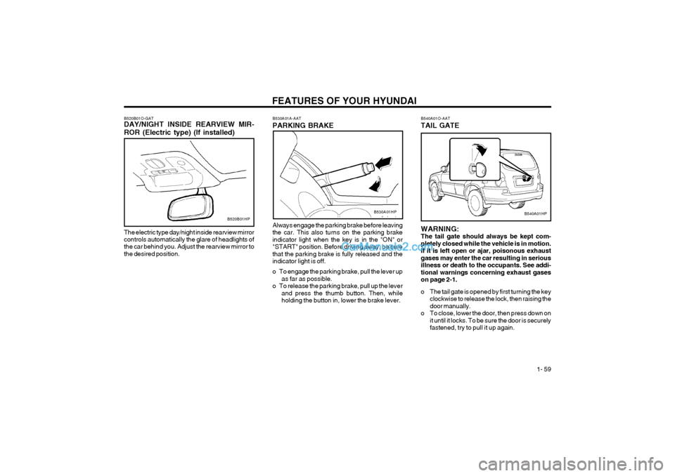
Always engage the parking brake before leaving the car. This also turns on the parking brakeindicator light when the key is in the "ON" or"START" position. Before driving away, be surethat the parking brake is fully released and theindicator light is off.
o To engage the parking brake, pull the lever upas far as possible.
o To release the parking brake, pull up the lever and press the thumb button. Then, while holding the button in, lower the brake lever.
B530A01A-AAT PARKING BRAKE
B520B01O-GAT DAY/NIGHT INSIDE REARVIEW MIR- ROR (Electric type) (If installed)
B520B01HP
The electric type day/night inside rearview mirror controls automatically the glare of headlights of the car behind you. Adjust the rearview mirror tothe desired position.B530A01HP
B540A01O-AAT TAIL GATE
B540A01HP
WARNING: The tail gate should always be kept com-pletely closed while the vehicle is in motion.If it is left open or ajar, poisonous exhaustgases may enter the car resulting in seriousillness or death to the occupants. See addi-tional warnings concerning exhaust gaseson page 2-1.
o The tail gate is opened by first turning the key clockwise to release the lock, then raising the door manually.
o To close, lower the door, then press down on it until it locks. To be sure the door is securelyfastened, try to pull it up again.
Page 190 of 361
INDEX 10-3
High-Mounted Rear Stoplight ............................................................
1-62
Hood Release ................................................................................... 1-63
Horn .................................................................................................. 1-64
I Ignition Switch ..................................................................................... 2-2
Immobilizer System .................................................................... 1-3 ~ 1-6
Limp Home Procedures ....................................... 1-3 ~ 1-4, 1-5 ~ 1-6
Key ........................................................................................... 1-3, 1-4
Instrument Cluster and Indicator ............................................ 1-35 ~ 1-38
Instrument Panel Light Control (Rheostat) .......................................1-52
Instruments and Controls ................ ..................................................1-34
Intermittent Wiper .............................................................................. 1-50
J Jump Starting ...................................................................................... 3-1
K
Key ...................................................................................................... 1-2 If you lose your keys .................................................................... 3-11
Positions .......................................................................................... 2-2
L
Light Bulbs Replacement ................ ..................................................6-23
Limited-Slip Differential ..................................................................... 2-13Luggage Compartment
Cargo Security Screen .................................................................. 1-61
Light ............................................................................................... 1-60
Net ................................................................................................. 1-60
MMaintenance Intervals Explanation of scheduled maintenance items ........................ 5-7 ~ 5-8
Maintenance under severe usage conditions ................................. 5-6
Scheduled maintenance ......................................................... 5-2 ~ 5-5
Service requirements ...................................................................... 5-1
Mirrors
Day-night inside rearview ................................................... 1-58 ~ 1-59
Outside rear view .......................................................................... 1-56
Multimeter ............................................................................... 1-45 ~ 1-47
Altimeter ........................................................................................ 1-46
Azimuth compass .......................................................................... 1-45
Barometer ...................................................................................... 1-47
Digital Clock .................................................................................. 1-47
Relative altimeter ........................................................................... 1-46
O Odometer .......................................................................................... 1-44
P Parking Brake ................................................................................... 1-59
Part-time 4WD Operation ......................................................... 2-9 ~ 2-10
Power Driver's Seat .......................................................................... 1-13
Page 202 of 361
CONTROLS AND EQUIPMENT
1- 2 YB020A1-E BEFORE ENTERING THE VEHICLE
o Ensure that all windows, mirrors and lamps are clean.
o Check condition of all tyres.
o Ensure that no fluid leaks are evident.
o Ensure that the area around the vehicle is clear before driving off.
YB020B1-E AFTER ENTERING THE VEHICLE
o Ensure that all occupants fasten and cor- rectly adjust seat belts.
o Ensure that seat and headrestraint positions are adjusted for optimum safety, control and comfort.
o Adjust interior and exterior rear view mir- rors.
o Verify correct operation of lamps, horn and other electrical equipment.
o Ensure that warning lamps illuminate when ignition is turned on.
NOTE: Fluid levels such as engine oil, engine cool- ant, brake and windscreen washer fluidshould be checked daily or at each refuel-ling, whichever occurs sooner. B020A01FC-EAT RUNNING IN YOUR NEW HYUNDAIThe longevity and performance of the vehicle are greatly affected by the care exercised dur-ing the first 1000 miles of motoring. Because ofmodern manufacturing techniques, rigid guide-lines regarding maximum road speeds havebecome unnecessary. However, certain pre-cautions should be observed in order to obtainthe best possible performance and useful lifefrom the vehicle.
1) Do not race the engine without a load (i.e revving the engine in neutral).
2) During the first 500 miles the maximum engine speed should be restricted to 3000rpm and gradually increased thereafter.
3) Avoid prolonged constant speed operation. The internal components of the engine willbecome run-in more quickly if the operation
speed is varied during the running in period.
4) Never allow the engine to labour. Use the gearbox freely and avoid large throttle open-ings when the engine speed is below 1500rpm.
5) Avoid rapid acceleration and maximum throttle openings.
6) Avoid harsh braking during the first 100 miles of urban motoring or 1000 miles ofmotorway driving to allow the friction facingsof the brake pads and shoes to bed againstthe discs and drums properly.
7) No trailer towing should be undertaken dur- ing the running-in period. B880A01HP-EAT IMMOBILISER SYSTEM
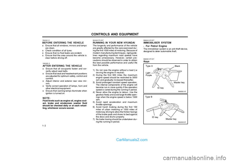
- For Petrol Engine The immobiliser system is an anti-theft device, designed to deter automobile theft. B880B01HP-EAT Keys
B880B01HP
B880B02HP
Light Purple
ID key
ID key Master key
Master key
Type B
Black
Type A
Page 257 of 361
CONTROLS AND EQUIPMENT1- 57
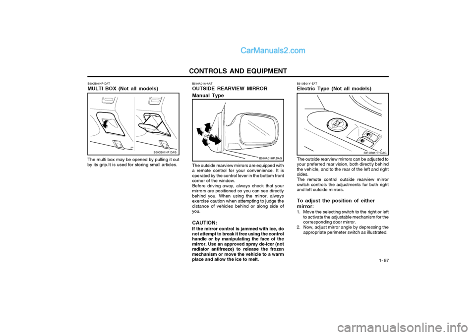
The outside rearview mirrors are equipped with
a remote control for your convenience. It is operated by the control lever in the bottom frontcorner of the window. Before driving away, always check that your
mirrors are positioned so you can see directlybehind you. When using the mirror, alwaysexercise caution when attempting to judge thedistance of vehicles behind or along side ofyou. CAUTION:
If the mirror control is jammed with ice, do
not attempt to break it free using the control handle or by manipulating the face of themirror. Use an approved spray de-icer (notradiator antifreeze) to release the frozenmechanism or move the vehicle to a warmplace and allow the ice to melt. B510A01A-AAT OUTSIDE REARVIEW MIRROR Manual Type
B510A01HP.DAG
B510B01Y-EAT Electric Type (Not all models)B510B01HP.DAG
The outside rearview mirrors can be adjusted to your preferred rear vision, both directly behindthe vehicle, and to the rear of the left and rightsides. The remote control outside rearview mirror switch controls the adjustments for both rightand left outside mirrors. To adjust the position of either mirror:
1. Move the selecting switch to the right or left to activate the adjustable mechanism for the corresponding door mirror.
2. Now, adjust mirror angle by depressing the appropriate perimeter switch as illustrated.B500B01HP.DAG
The multi box may be opened by pulling it out
by its grip.It is used for storing small articles. B500B01HP-DAT MULTI BOX (Not all models)
Page 258 of 361
CONTROLS AND EQUIPMENT
1- 58 B510C01HP.DAG
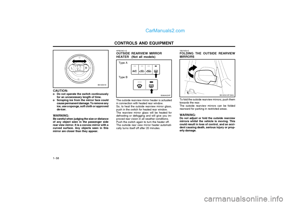
YB270D2-E FOLDING THE OUTSIDE REARVIEW MIRRORS To fold the outside rearview mirrors, push them towards the rear. The outside rearview mirrors can be folded rearward for parking in restricted areas. WARNING: Do not adjust or fold the outside rearviewmirrors whilst the vehicle is moving. Thiscould result in loss of control, and an acci-dent causing death, serious injury or prop-erty damage.
CAUTION:
o Do not operate the switch continuously for an unnecessary length of time.
o Scraping ice from the mirror face could cause permanent damage. To remove anyice, use a sponge, soft cloth or approvedde-icer.
WARNING: Be careful when judging the size or distance
of any object seen in the passenger side rear view mirror. It is a convex mirror with acurved surface. Any objects seen in thismirror are closer than they appear. HPB270C1-E OUTSIDE REARVIEW MIRROR HEATER (Not all models) The outside rearview mirror heater is actuated in connection with heated rear window. So, to heat the outside rearview mirror glass, push in the switch for heated rear window. The rearview mirror glass will be heated for defrosting or defogging and will give you im-proved rear vision in all weather conditions. Push the switch again to turn the heater off. The outside rear view mirror heater automati-cally turns itself off after 20 minutes.
B510D01E
B380A02HP
Type A
Type B
Page 259 of 361
CONTROLS AND EQUIPMENT1- 59
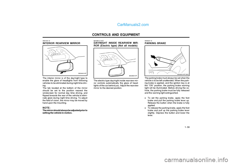
B520B01O-EAT DAY/NIGHT INSIDE REARVIEW MIR- ROR (Electric type) (Not all models) The electric type day/night inside rearview mir-
ror controls automatically the glare of head- lights of the car behind you. Adjust the rearviewmirror to the desired position.
SB370A1-E INTERIOR REARVIEW MIRROR The interior mirror is of the day/night type to
enable the glare of headlights from following vehicles to be eliminated during night time driv-ing.
The tab located at the bottom of the mirror
should be set to the position nearest thewindscreen for normal day time driving, andflipped towards the rear of the vehicle to elimi-nate glare during night time driving. To adjustthe field of vision, the mirror may be moved byhand upon the mounting. NOTE: The mirror should always be adjusted prior tosetting the vehicle in motion.
B520A01HPB520B01HP
SB380A1-E PARKING BRAKE The parking brake must always be set when the
vehicle is to be left unattended. When the park- ing brake is applied, and the ignition key is atthe "ON" position, the parking brake warninglight will be illuminated. Before driving the ve-hicle, the parking brake must be fully releasedand the warning light extinguished.
o To set the parking brake, apply the foot brake and pull the parking brake lever up. Release the button when the brake is fullyapplied.
o To release the parking brake, apply the foot brake and pull up the parking brake leverslightly. Depress the button and lower thelever.
B530A01HP.DAG
Page 263 of 361
CONTROLS AND EQUIPMENT1- 63
B570A02HP
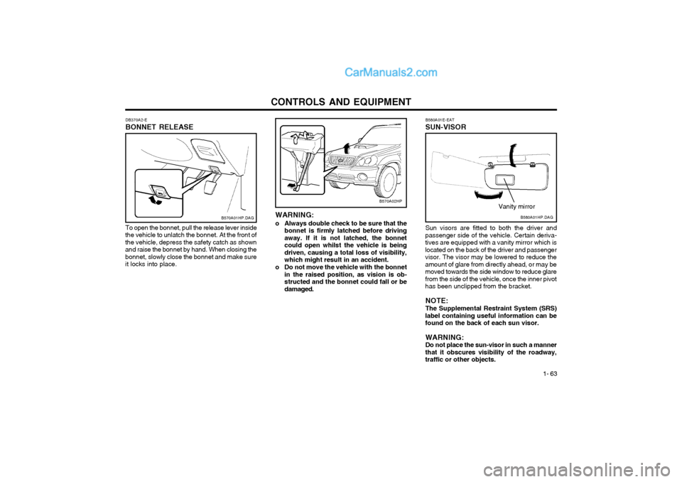
DB370A2-E BONNET RELEASE
B570A01HP.DAG
To open the bonnet, pull the release lever inside
the vehicle to unlatch the bonnet. At the front of the vehicle, depress the safety catch as shownand raise the bonnet by hand. When closing thebonnet, slowly close the bonnet and make sureit locks into place. WARNING:
o Always double check to be sure that the bonnet is firmly latched before drivingaway. If it is not latched, the bonnetcould open whilst the vehicle is beingdriven, causing a total loss of visibility,which might result in an accident.
o Do not move the vehicle with the bonnet in the raised position, as vision is ob-structed and the bonnet could fall or bedamaged. B580A01E-EAT SUN-VISORB580A01HP.DAG
Vanity mirror
Sun visors are fitted to both the driver and
passenger side of the vehicle. Certain deriva- tives are equipped with a vanity mirror which islocated on the back of the driver and passengervisor. The visor may be lowered to reduce theamount of glare from directly ahead, or may bemoved towards the side window to reduce glarefrom the side of the vehicle, once the inner pivothas been unclipped from the bracket.
NOTE: The Supplemental Restraint System (SRS)
label containing useful information can be found on the back of each sun visor.
WARNING:Do not place the sun-visor in such a manner
that it obscures visibility of the roadway,traffic or other objects.
Page 359 of 361
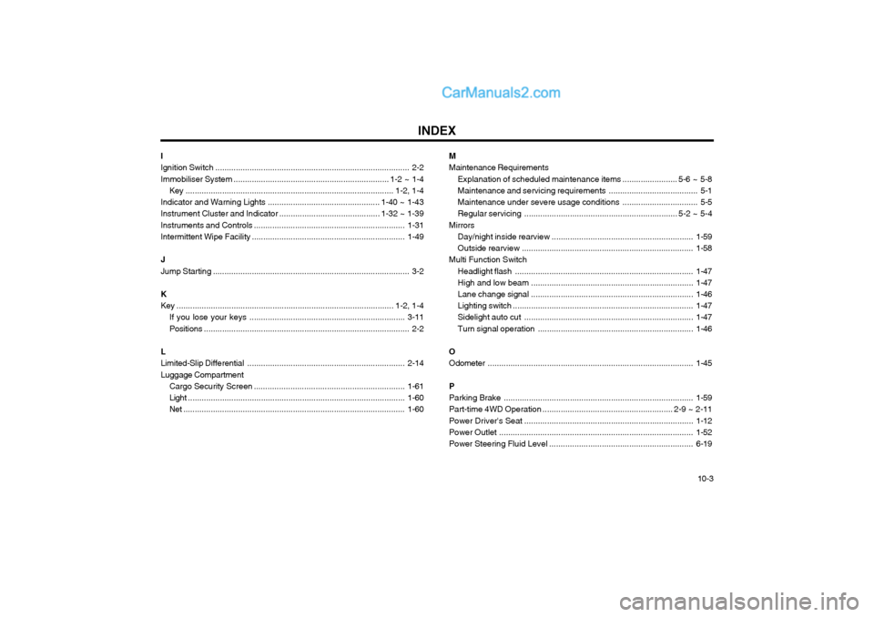
INDEX10-3
M Maintenance Requirements
Explanation of scheduled maintenance items ........................ 5-6 ~ 5-8
Maintenance and servicing requirements ....................................... 5-1
Maintenance under severe usage conditions ................................. 5-5
Regular servicing ................................................................... 5-2 ~ 5-4
Mirrors Day/night inside rearview .............................................................. 1-59
Outside rearview ........................................................................... 1-58
Multi Function Switch
Headlight flash .............................................................................. 1-47
High and low beam ....................................................................... 1-47
Lane change signal ....................................................................... 1-46
Lighting switch ............................................................................... 1-47
Sidelight auto cut .......................................................................... 1-47
Turn signal operation .................................................................... 1-46
OOdometer .......................................................................................... 1-45
P Parking Brake ................................................................................... 1-59
Part-time 4WD Operation ......................................................... 2-9 ~ 2-11
Power Driver's Seat .......................................................................... 1-12
Power Outlet ..................................................................................... 1-52
Power Steering Fluid Level ............. ..................................................6-19
I Ignition Switch
..................................................................................... 2-2
Immobiliser System .................................................................... 1-2 ~ 1-4
Key ........................................................................................... 1-2, 1-4
Indicator and Warning Lights ................................................. 1-40 ~ 1-43
Instrument Cluster and Indicator ............................................ 1-32 ~ 1-39
Instruments and Controls ................ ..................................................1-31
Intermittent Wipe Facility ................................................................... 1-49
J Jump Starting ...................................................................................... 3-2
K
Key ............................................................................................... 1-2, 1-4 If you lose your keys .................................................................... 3-11
Positions .......................................................................................... 2-2
LLimited-Slip Differential ..................................................................... 2-14
Luggage Compartment Cargo Security Screen .................................................................. 1-61
Light ............................................................................................... 1-60
Net ................................................................................................. 1-60