tow Hyundai Terracan 2005 Workshop Manual
[x] Cancel search | Manufacturer: HYUNDAI, Model Year: 2005, Model line: Terracan, Model: Hyundai Terracan 2005Pages: 539, PDF Size: 18.03 MB
Page 361 of 539
1CONTROLS AND EQUIPMENT
56
!
B265B01HP-GAT
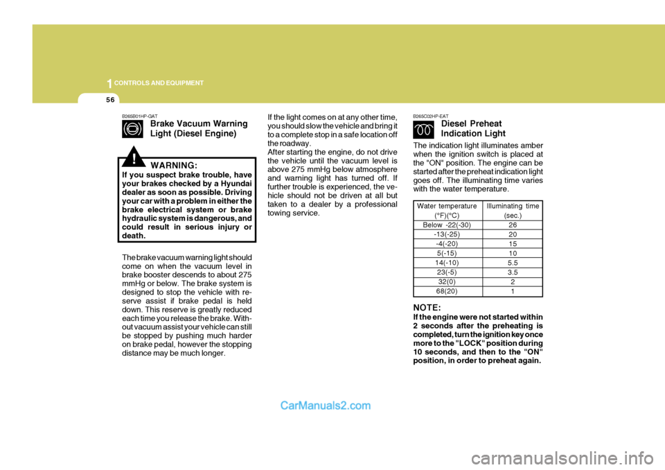
Brake Vacuum Warning Light (Diesel Engine)
The brake vacuum warning light should come on when the vacuum level in brake booster descends to about 275 mmHg or below. The brake system isdesigned to stop the vehicle with re- serve assist if brake pedal is held down. This reserve is greatly reducedeach time you release the brake. With- out vacuum assist your vehicle can still be stopped by pushing much harderon brake pedal, however the stopping distance may be much longer. WARNING:
If you suspect brake trouble, have your brakes checked by a Hyundai dealer as soon as possible. Driving your car with a problem in either thebrake electrical system or brake hydraulic system is dangerous, and could result in serious injury ordeath.If the light comes on at any other time, you should slow the vehicle and bring itto a complete stop in a safe location off the roadway. After starting the engine, do not drivethe vehicle until the vacuum level is above 275 mmHg below atmosphere and warning light has turned off. Iffurther trouble is experienced, the ve- hicle should not be driven at all but taken to a dealer by a professionaltowing service. B265C02HP-EAT
Diesel Preheat Indication Light
Water temperature
(°F)(°C)
Below -22(-30) -13(-25)
-4(-20)5(-15)
14(-10) 23(-5)32(0)
68(20) Illuminating time
(sec.)26 201510
5.53.5 21
NOTE: If the engine were not started within 2 seconds after the preheating is completed, turn the ignition key once more to the "LOCK" position during10 seconds, and then to the "ON" position, in order to preheat again.
The indication light illuminates amber when the ignition switch is placed at the "ON" position. The engine can be started after the preheat indication lightgoes off. The illuminating time varies with the water temperature.
Page 365 of 539
1CONTROLS AND EQUIPMENT
60
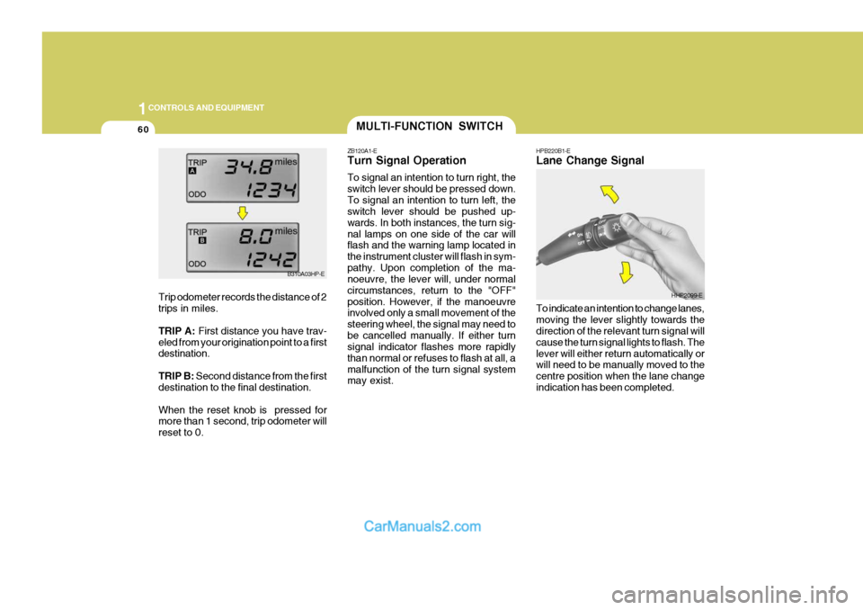
HPB220B1-E Lane Change Signal To indicate an intention to change lanes, moving the lever slightly towards the direction of the relevant turn signal will cause the turn signal lights to flash. Thelever will either return automatically or will need to be manually moved to the centre position when the lane changeindication has been completed.MULTI-FUNCTION SWITCH
ZB120A1-E Turn Signal Operation To signal an intention to turn right, the switch lever should be pressed down.To signal an intention to turn left, the switch lever should be pushed up- wards. In both instances, the turn sig-nal lamps on one side of the car will flash and the warning lamp located in the instrument cluster will flash in sym-pathy. Upon completion of the ma- noeuvre, the lever will, under normal circumstances, return to the "OFF"position. However, if the manoeuvre involved only a small movement of the steering wheel, the signal may need tobe cancelled manually. If either turn signal indicator flashes more rapidly than normal or refuses to flash at all, amalfunction of the turn signal system may exist.
HHP2099-E
B310A03HP-E
Trip odometer records the distance of 2 trips in miles. TRIP A: First distance you have trav-
eled from your origination point to a first destination. TRIP B: Second distance from the first
destination to the final destination.When the reset knob is pressed for more than 1 second, trip odometer will reset to 0.
Page 366 of 539
1
CONTROLS AND EQUIPMENT
61
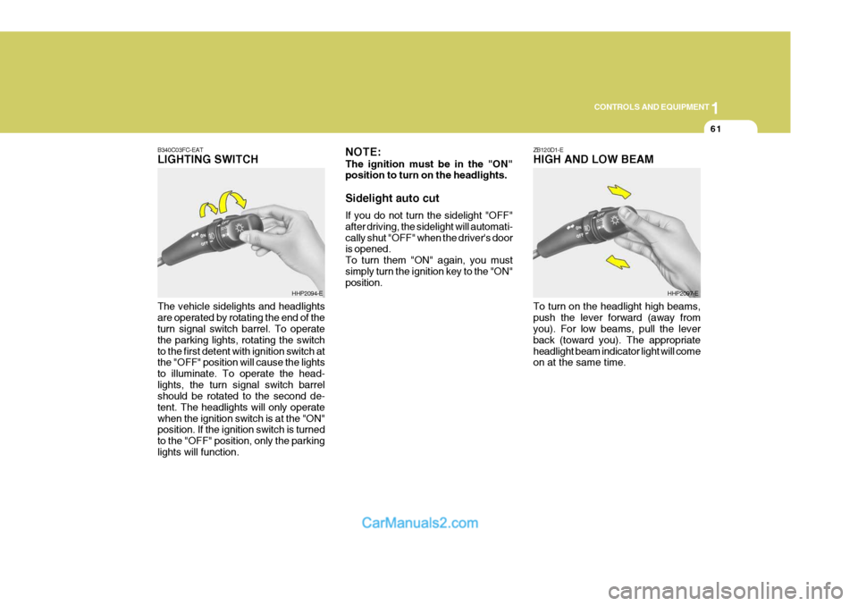
ZB120D1-E HIGH AND LOW BEAM
B340C03FC-EATLIGHTING SWITCH The vehicle sidelights and headlights are operated by rotating the end of the turn signal switch barrel. To operate the parking lights, rotating the switchto the first detent with ignition switch at the "OFF" position will cause the lights to illuminate. To operate the head-lights, the turn signal switch barrel should be rotated to the second de- tent. The headlights will only operatewhen the ignition switch is at the "ON" position. If the ignition switch is turned to the "OFF" position, only the parkinglights will function.
HHP2094-E NOTE: The ignition must be in the "ON" position to turn on the headlights. Sidelight auto cut If you do not turn the sidelight "OFF" after driving, the sidelight will automati-cally shut "OFF" when the driver's door is opened. To turn them "ON" again, you mustsimply turn the ignition key to the "ON" position.HHP2097-E
To turn on the headlight high beams, push the lever forward (away from you). For low beams, pull the lever back (toward you). The appropriateheadlight beam indicator light will come on at the same time.
Page 367 of 539
1CONTROLS AND EQUIPMENT
62FOG LIGHT SWITCH
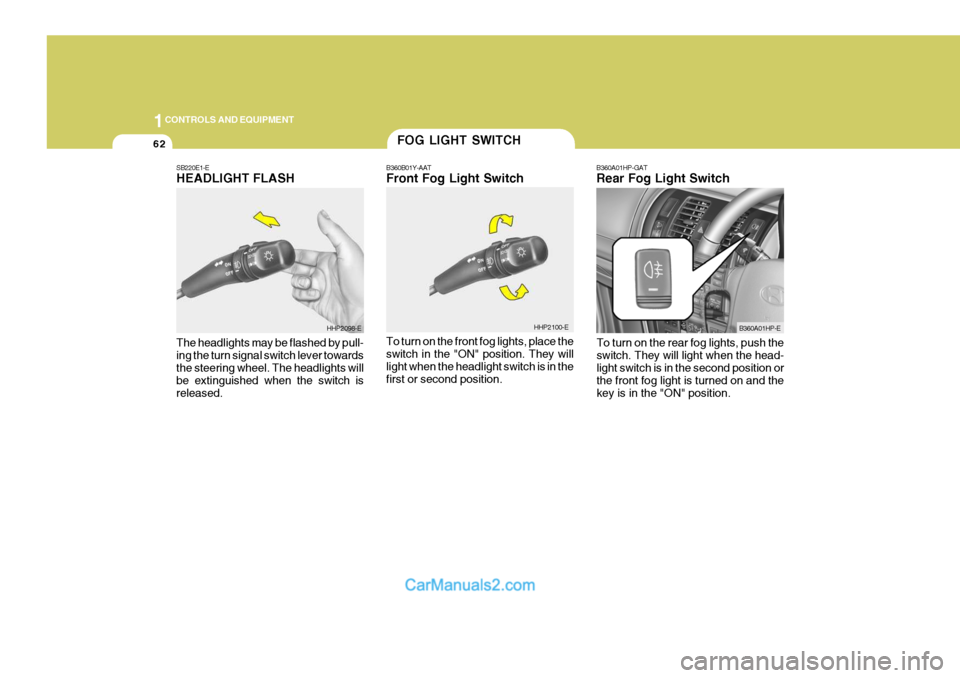
B360B01Y-AAT Front Fog Light Switch To turn on the front fog lights, place the switch in the "ON" position. They will light when the headlight switch is in thefirst or second position. B360A01HP-GAT Rear Fog Light Switch
HHP2100-E B360A01HP-E
SB220E1-EHEADLIGHT FLASH The headlights may be flashed by pull- ing the turn signal switch lever towards the steering wheel. The headlights will be extinguished when the switch isreleased.
HHP2098-E
To turn on the rear fog lights, push the switch. They will light when the head- light switch is in the second position or the front fog light is turned on and thekey is in the "ON" position.
Page 368 of 539
1
CONTROLS AND EQUIPMENT
63
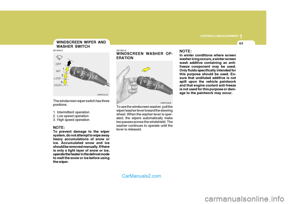
The windscreen wiper switch has three positions.
1. Intermittent operation
2. Low speed operation
3. High speed operation NOTE: To prevent damage to the wiper system, do not attempt to wipe awayheavy accumulations of snow or ice. Accumulated snow and ice should be removed manually. If thereis only a light layer of snow or ice, operate the heater in the defrost mode to melt the snow or ice before usingthe wiper.WINDSCREEN WIPER AND WASHER SWITCH
ZB130A2-E
HHP2101-E
1
OB130B1-E WINDSCREEN WASHER OP- ERATION To use the windscreen washer, pull the wiper/washer lever toward the steeringwheel. When the washer lever is oper- ated, the wipers automatically make two passes across the windshield. Thewasher continues to operate until the lever is released. NOTE: In winter conditions where screen washer icing occurs, a winter screen wash additive containing an anti-freeze component may be used. Only fluids specifically intended for this purpose should be used. En-sure that undiluted additive is not spilt upon the vehicle paintwork and that engine coolant anti-freezeis not used for this purpose or dam- age to the paintwork may occur.
HHP2103-E
2 3
Page 382 of 539
1
CONTROLS AND EQUIPMENT
77
!
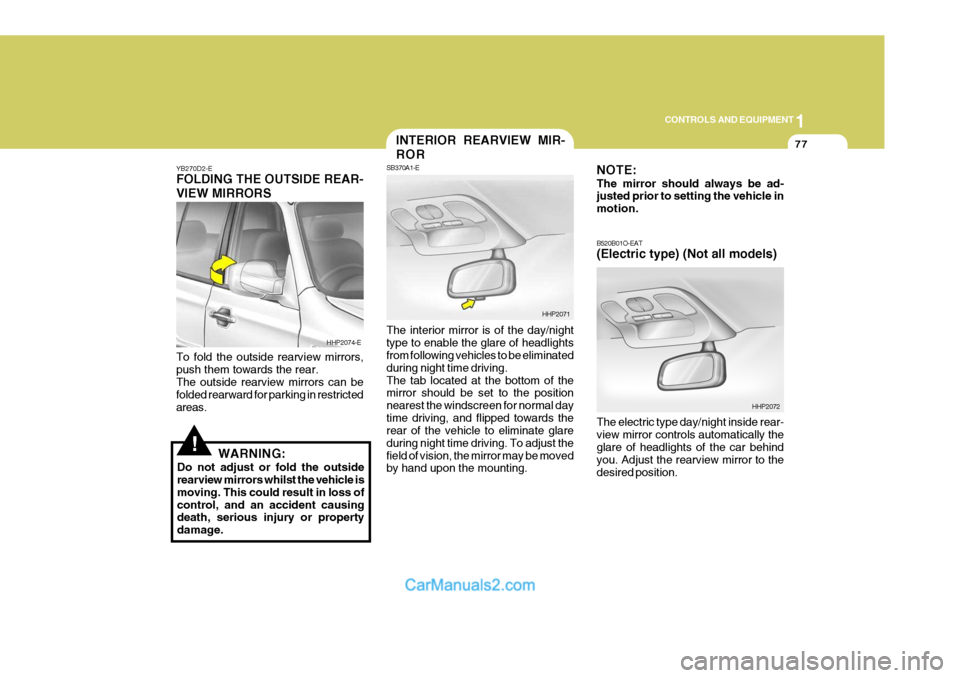
YB270D2-E FOLDING THE OUTSIDE REAR- VIEW MIRRORS To fold the outside rearview mirrors, push them towards the rear. The outside rearview mirrors can be folded rearward for parking in restrictedareas.
WARNING:
Do not adjust or fold the outside rearview mirrors whilst the vehicle is moving. This could result in loss ofcontrol, and an accident causing death, serious injury or property damage. The interior mirror is of the day/nighttype to enable the glare of headlights from following vehicles to be eliminated during night time driving.The tab located at the bottom of the mirror should be set to the position nearest the windscreen for normal daytime driving, and flipped towards the rear of the vehicle to eliminate glare during night time driving. To adjust thefield of vision, the mirror may be moved by hand upon the mounting.
HHP2074-E
HHP2071
INTERIOR REARVIEW MIR- ROR
SB370A1-E NOTE: The mirror should always be ad- justed prior to setting the vehicle in motion. B520B01O-EAT (Electric type) (Not all models) The electric type day/night inside rear- view mirror controls automatically the glare of headlights of the car behind you. Adjust the rearview mirror to thedesired position.
HHP2072
Page 385 of 539
1CONTROLS AND EQUIPMENT
80
B650A01S-AAT Stowage Precautions
1. Do not place objects on the cargosecurity screen. Such objects may be thrown about inside the vehicle and possibly injure vehicle occu- pants during an accident or whenbraking.
2. For better fuel economy, do not
carry unnecessary weight.
3. Never allow anyone to ride in the luggage compartment. It is designedfor luggage only.
4. Try to maintain the balance of the vehicle and locate the weight as farforward as possible.CARGO SECURITY SCREEN
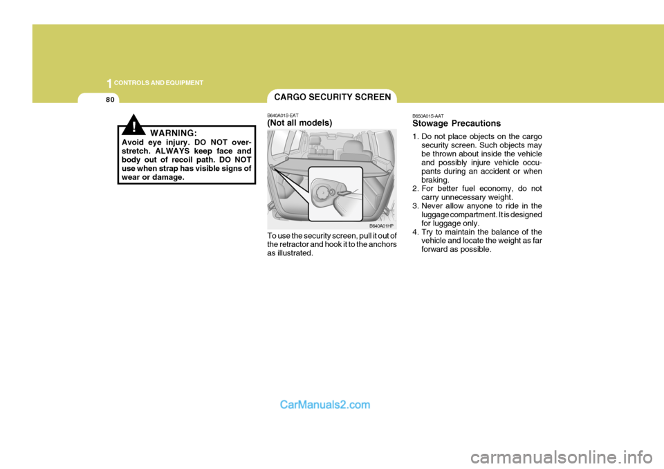
B640A01S-EAT (Not all models) To use the security screen, pull it out of the retractor and hook it to the anchors as illustrated. B640A01HP
!WARNING:
Avoid eye injury. DO NOT over- stretch. ALWAYS keep face andbody out of recoil path. DO NOT use when strap has visible signs of wear or damage.
Page 388 of 539
1
CONTROLS AND EQUIPMENT
83
HHP2017-1
BONNET RELEASE
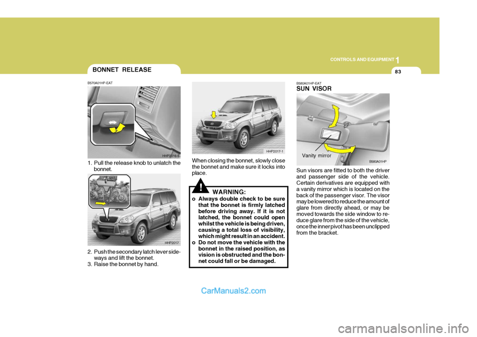
2. Push the secondary latch lever side-
ways and lift the bonnet.
3. Raise the bonnet by hand. B570A01HP-EAT
1. Pull the release knob to unlatch the
bonnet. HHP2016-E
HHP2017
!
When closing the bonnet, slowly close the bonnet and make sure it locks into place. WARNING:
o Always double check to be sure that the bonnet is firmly latched before driving away. If it is not latched, the bonnet could open whilst the vehicle is being driven,causing a total loss of visibility, which might result in an accident.
o Do not move the vehicle with the bonnet in the raised position, asvision is obstructed and the bon- net could fall or be damaged. B580A01HP-EAT SUN VISOR Sun visors are fitted to both the driver and passenger side of the vehicle. Certain derivatives are equipped with a vanity mirror which is located on theback of the passenger visor. The visor may be lowered to reduce the amount of glare from directly ahead, or may bemoved towards the side window to re- duce glare from the side of the vehicle, once the inner pivot has been unclippedfrom the bracket.B580A01HPVanity mirror
Page 390 of 539
1
CONTROLS AND EQUIPMENT
85
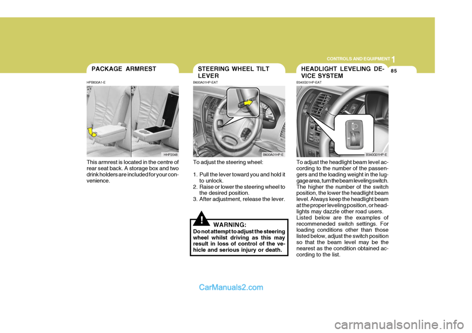
This armrest is located in the centre of rear seat back. A storage box and two drink holders are included for your con- venience.PACKAGE ARMREST
HPB830A1-E
HHP2048
!
To adjust the steering wheel:
1. Pull the lever toward you and hold it to unlock.
2. Raise or lower the steering wheel to the desired position.
3. After adjustment, release the lever.
WARNING:
Do not attempt to adjust the steering wheel whilst driving as this may result in loss of control of the ve- hicle and serious injury or death. To adjust the headlight beam level ac-cording to the number of the passen- gers and the loading weight in the lug- gage area, turn the beam leveling switch.The higher the number of the switch position, the lower the headlight beam level. Always keep the headlight beamat the proper leveling position, or head- lights may dazzle other road users. Listed below are the examples ofrecommeneded switch settings. For loading conditions other than those listed below, adjust the switch positionso that the beam level may be the nearest as the condition obtained ac- cording to the list.
STEERING WHEEL TILT LEVER
B600A01HP-EAT
B600A01HP-E
HEADLIGHT LEVELING DE- VICE SYSTEM
B340G01HP-EAT
B340G01HP-E
Page 401 of 539
1CONTROLS AND EQUIPMENT
96
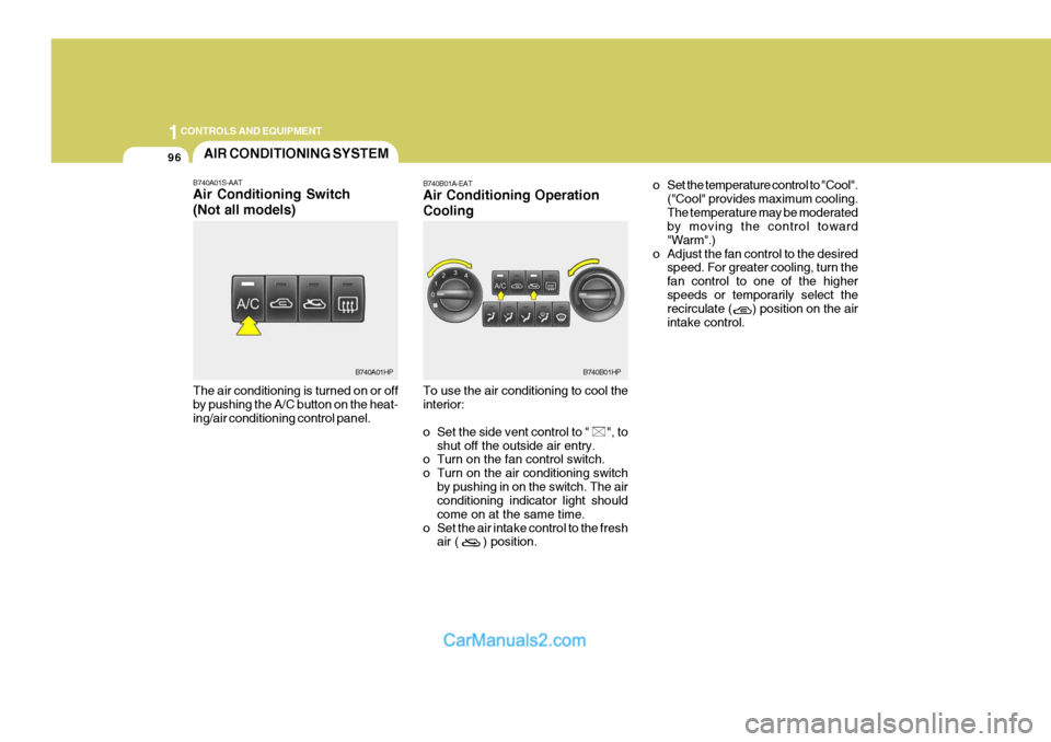
The air conditioning is turned on or off by pushing the A/C button on the heat- ing/air conditioning control panel.AIR CONDITIONING SYSTEM
B740A01S-AAT Air Conditioning Switch (Not all models)
B740A01HP B740B01A-EAT Air Conditioning Operation Cooling To use the air conditioning to cool the interior:
o Set the side vent control to " ", to
shut off the outside air entry.
o Turn on the fan control switch.
o Turn on the air conditioning switch
by pushing in on the switch. The air conditioning indicator light should come on at the same time.
o Set the air intake control to the fresh air ( ) position. o Set the temperature control to "Cool".
("Cool" provides maximum cooling.The temperature may be moderated by moving the control toward "Warm".)
o Adjust the fan control to the desired speed. For greater cooling, turn thefan control to one of the higherspeeds or temporarily select the recirculate ( ) position on the air intake control.B740B01HP