Hyundai Tiburon 2006 Owner's Manual
Tiburon 2006
Hyundai
Hyundai
https://www.carmanualsonline.info/img/35/19689/w960_19689-0.png
Hyundai Tiburon 2006 Owner's Manual
Trending: seat memory, power steering, towing capacity, oil type, dashboard, instrument cluster, trunk release
Page 221 of 266
6
DO-IT-YOURSELF MAINTENANCE
27
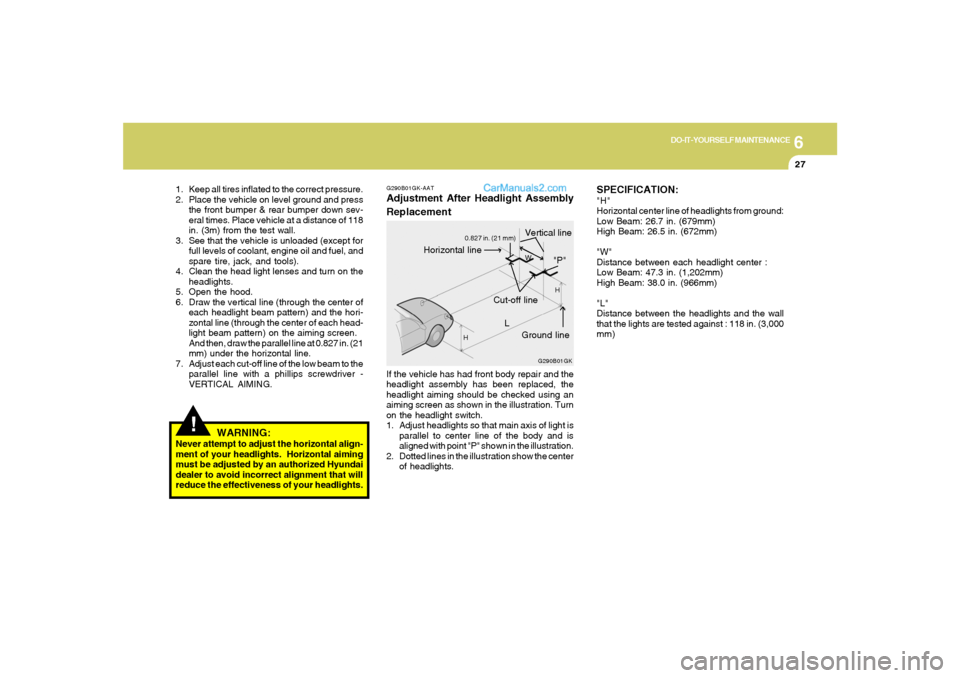
G290B01GK-AATAdjustment After Headlight Assembly
ReplacementIf the vehicle has had front body repair and the
headlight assembly has been replaced, the
headlight aiming should be checked using an
aiming screen as shown in the illustration. Turn
on the headlight switch.
1. Adjust headlights so that main axis of light is
parallel to center line of the body and is
aligned with point "P" shown in the illustration.
2. Dotted lines in the illustration show the center
of headlights.
G290B01GK
L
W
H
H
Cut-off line
Ground line
"P"
Horizontal line
Vertical line
0.827 in. (21 mm)
!
1. Keep all tires inflated to the correct pressure.
2. Place the vehicle on level ground and press
the front bumper & rear bumper down sev-
eral times. Place vehicle at a distance of 118
in. (3m) from the test wall.
3. See that the vehicle is unloaded (except for
full levels of coolant, engine oil and fuel, and
spare tire, jack, and tools).
4. Clean the head light lenses and turn on the
headlights.
5. Open the hood.
6. Draw the vertical line (through the center of
each headlight beam pattern) and the hori-
zontal line (through the center of each head-
light beam pattern) on the aiming screen.
And then, draw the parallel line at 0.827 in. (21
mm) under the horizontal line.
7. Adjust each cut-off line of the low beam to the
parallel line with a phillips screwdriver -
VERTICAL AIMING.
WARNING:
Never attempt to adjust the horizontal align-
ment of your headlights. Horizontal aiming
must be adjusted by an authorized Hyundai
dealer to avoid incorrect alignment that will
reduce the effectiveness of your headlights.
SPECIFICATION:"H"
Horizontal center line of headlights from ground:
Low Beam: 26.7 in. (679mm)
High Beam: 26.5 in. (672mm)
"W"
Distance between each headlight center :
Low Beam: 47.3 in. (1,202mm)
High Beam: 38.0 in. (966mm)
"L"
Distance between the headlights and the wall
that the lights are tested against : 118 in. (3,000
mm)
Page 222 of 266
6
DO-IT-YOURSELF MAINTENANCE
28
HGK5024
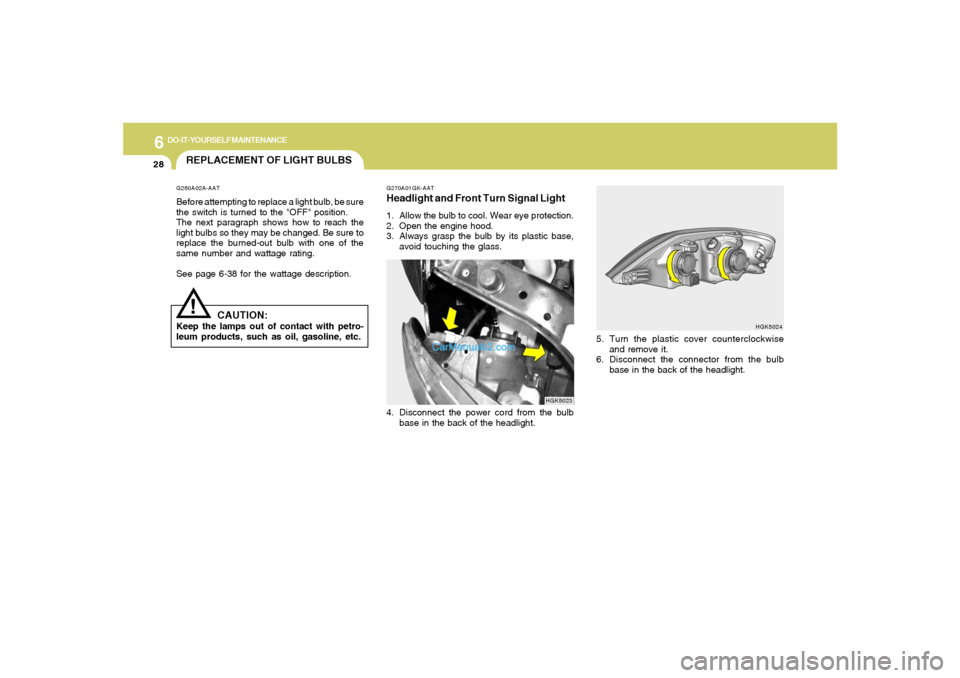
5. Turn the plastic cover counterclockwise
and remove it.
6. Disconnect the connector from the bulb
base in the back of the headlight.
REPLACEMENT OF LIGHT BULBS!
G260A02A-AATBefore attempting to replace a light bulb, be sure
the switch is turned to the "OFF" position.
The next paragraph shows how to reach the
light bulbs so they may be changed. Be sure to
replace the burned-out bulb with one of the
same number and wattage rating.
See page 6-38 for the wattage description.
CAUTION:
Keep the lamps out of contact with petro-
leum products, such as oil, gasoline, etc.
G270A01GK-AATHeadlight and Front Turn Signal Light1. Allow the bulb to cool. Wear eye protection.
2. Open the engine hood.
3. Always grasp the bulb by its plastic base,
avoid touching the glass.4. Disconnect the power cord from the bulb
base in the back of the headlight.
HGK5023
Page 223 of 266
6
DO-IT-YOURSELF MAINTENANCE
29
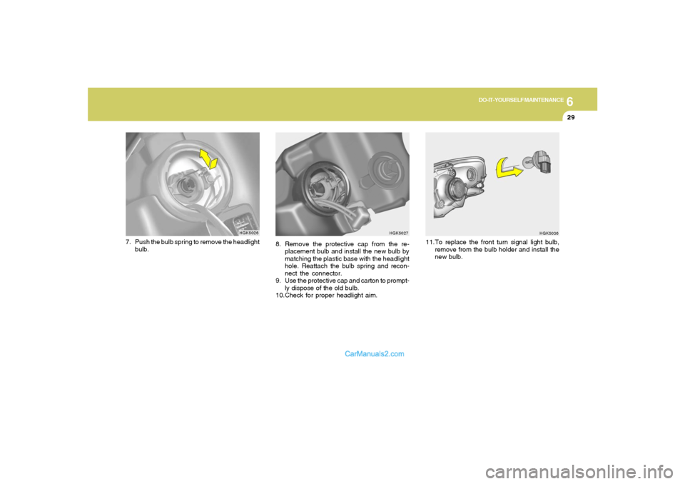
8. Remove the protective cap from the re-
placement bulb and install the new bulb by
matching the plastic base with the headlight
hole. Reattach the bulb spring and recon-
nect the connector.
9. Use the protective cap and carton to prompt-
ly dispose of the old bulb.
10.Check for proper headlight aim.
HGK5027
HGK5026
7. Push the bulb spring to remove the headlight
bulb.
HGK5036
11.To replace the front turn signal light bulb,
remove from the bulb holder and install the
new bulb.
Page 224 of 266
6
DO-IT-YOURSELF MAINTENANCE
30
HGK5041
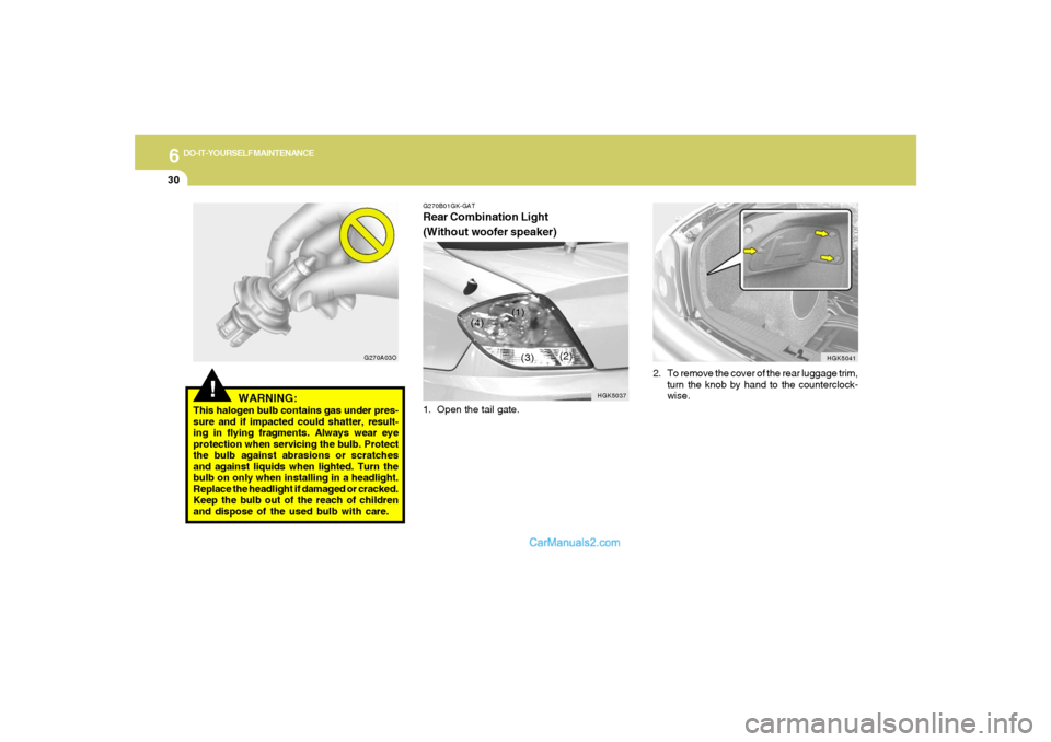
2. To remove the cover of the rear luggage trim,
turn the knob by hand to the counterclock-
wise.
!
WARNING:
This halogen bulb contains gas under pres-
sure and if impacted could shatter, result-
ing in flying fragments. Always wear eye
protection when servicing the bulb. Protect
the bulb against abrasions or scratches
and against liquids when lighted. Turn the
bulb on only when installing in a headlight.
Replace the headlight if damaged or cracked.
Keep the bulb out of the reach of children
and dispose of the used bulb with care.
G270A03OG270B01GK-GAT
Rear Combination Light
(Without woofer speaker)1. Open the tail gate.
HGK5037
(1)
(2)
(3) (4)
Page 225 of 266
6
DO-IT-YOURSELF MAINTENANCE
31
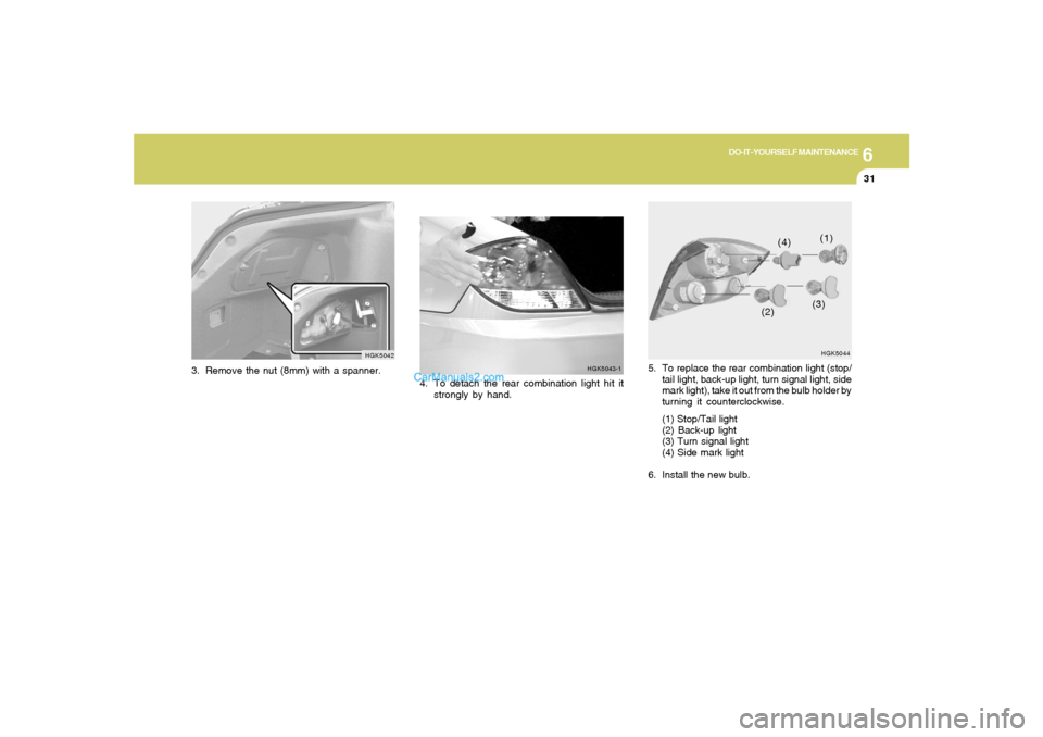
5. To replace the rear combination light (stop/
tail light, back-up light, turn signal light, side
mark light), take it out from the bulb holder by
turning it counterclockwise.
(1) Stop/Tail light
(2) Back-up light
(3) Turn signal light
(4) Side mark light
6. Install the new bulb.
HGK5044(1)
(2)(3) (4)
HGK5042
3. Remove the nut (8mm) with a spanner.
4. To detach the rear combination light hit it
strongly by hand.
HGK5043-1
Page 226 of 266
6
DO-IT-YOURSELF MAINTENANCE
32
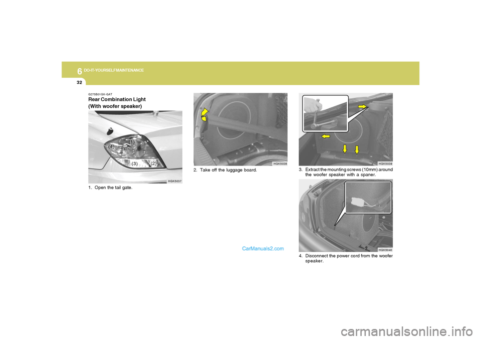
2. Take off the luggage board.
HGK5038 G275B01GK-GAT
Rear Combination Light
(With woofer speaker)
HGK5037
(1)
(2)
(3) (4)
1. Open the tail gate.
HGK5039
HGK5040
3. Extract the mounting screws (10mm) around
the woofer speaker with a spaner.
4. Disconnect the power cord from the woofer
speaker.
Page 227 of 266
6
DO-IT-YOURSELF MAINTENANCE
33
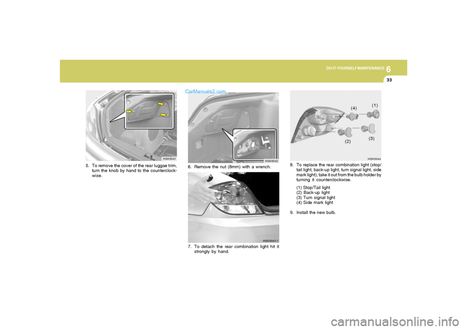
HGK5044(1)
(2)(3) (4)
8. To replace the rear combination light (stop/
tail light, back-up light, turn signal light, side
mark light), take it out from the bulb holder by
turning it counterclockwise.
(1) Stop/Tail light
(2) Back-up light
(3) Turn signal light
(4) Side mark light
9. Install the new bulb.
HGK5041
5. To remove the cover of the rear luggae trim,
turn the knob by hand to the counterclock-
wise.
HGK5042
6. Remove the nut (8mm) with a wrench.
HGK5043-1
7. To detach the rear combination light hit it
strongly by hand.
Page 228 of 266
6
DO-IT-YOURSELF MAINTENANCE
34
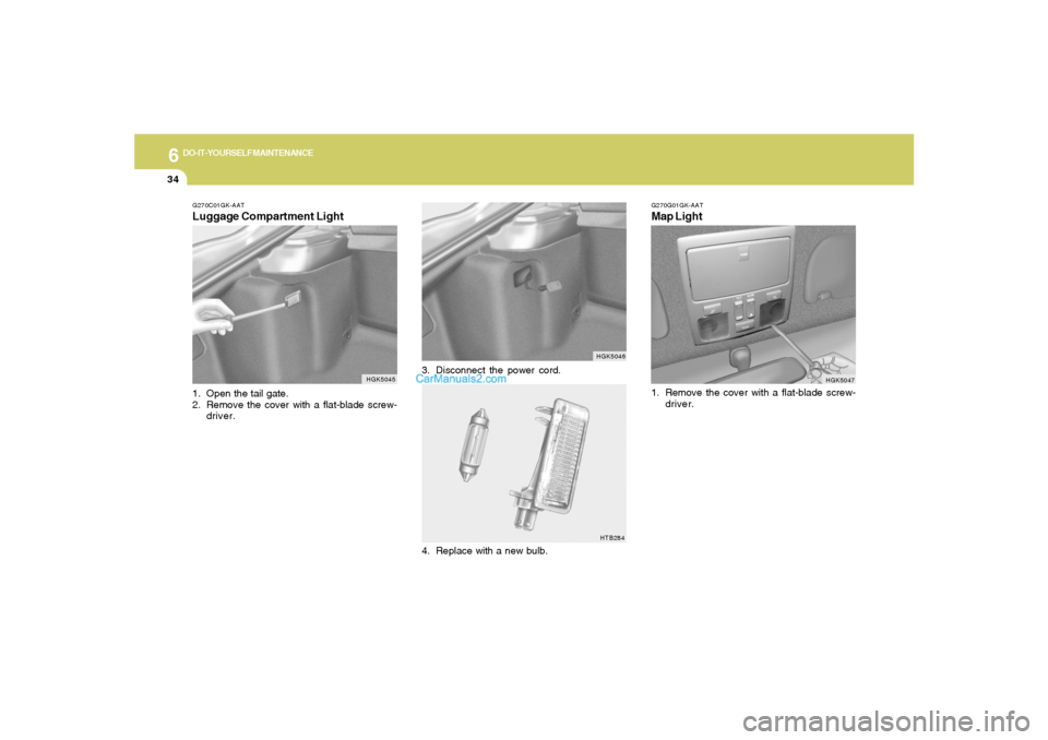
3. Disconnect the power cord.
HGK5046HTB284
G270C01GK-AATLuggage Compartment Light1. Open the tail gate.
2. Remove the cover with a flat-blade screw-
driver.
HGK5045
4. Replace with a new bulb.
G270G01GK-AATMap Light
HGK5047
1. Remove the cover with a flat-blade screw-
driver.
Page 229 of 266
6
DO-IT-YOURSELF MAINTENANCE
35
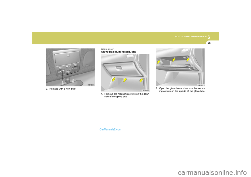
HGK2112
2. Open the glove box and remove the mount-
ing screws on the upside of the glove box.
HGK5048
G270H01GK-GATGlove Box Illuminated Light1. Remove the mounting screws on the down-
side of the glove box.
HGK2111
2. Replace with a new bulb.
Page 230 of 266
6
DO-IT-YOURSELF MAINTENANCE
36
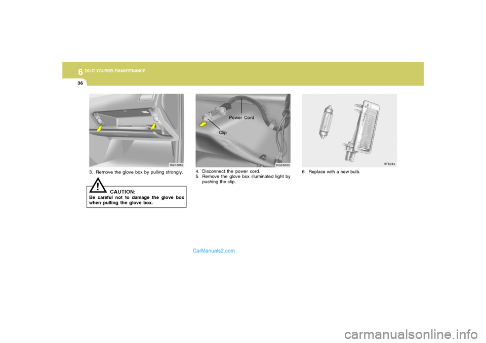
HGK5053
ClipPower Cord
4. Disconnect the power cord.
5. Remove the glove box illuminated light by
pushing the clip. 3. Remove the glove box by pulling strongly.
CAUTION:
Be careful not to damage the glove box
when pulling the glove box.
!
HGK5052
HTB284
6. Replace with a new bulb.
Trending: flat tire, jump cable, oil viscosity, suspension, trip computer, transmission oil, reset sun roof

