charging HYUNDAI TUCSON 2016 Owners Manual
[x] Cancel search | Manufacturer: HYUNDAI, Model Year: 2016, Model line: TUCSON, Model: HYUNDAI TUCSON 2016Pages: 642, PDF Size: 9.78 MB
Page 20 of 642
F20
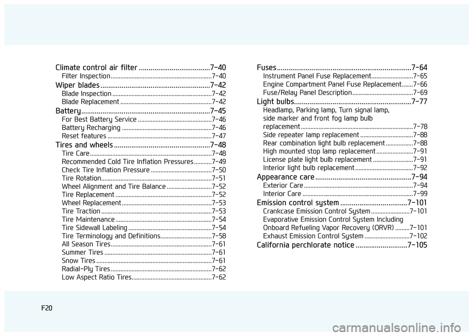
Climate control air filter .....................................7-40
Filter Inspection ...............................................................7-40
Wiper blades .........................................................7-42
Blade Inspection ..............................................................7-42
Blade Replacement .........................................................7-42
Battery...................................................................7-45
For Best Battery Service ..............................................7-46
Battery Recharging ........................................................7-46
Reset features .................................................................7-47
Tires and wheels ..................................................7-48
Tire Care ............................................................................7-48
Recommended Cold Tire Inflation Pressures ...........7-49
Check Tire Inflation Pressure ......................................7-50
Tire Rotation.....................................................................7-51
Wheel Alignment and Tire Balance ............................7-52
Tire Replacement ............................................................7-52
Wheel Replacement ........................................................7-53
Tire Traction .....................................................................7-53
Tire Maintenance ............................................................7-54
Tire Sidewall Labeling ....................................................7-54
Tire Terminology and Definitions................................7-58
All Season Tires ...............................................................7-61
Summer Tires ...................................................................7-61
Snow Tires ........................................................................7-61
Radial-Ply Tires ...............................................................7-62
Low Aspect Ratio Tires..................................................7-62
Fuses ......................................................................7-64
Instrument Panel Fuse Replacement..........................7-65
Engine Compartment Panel Fuse Replacement.......7-66
Fuse/Relay Panel Description ......................................7-69
Light bulbs.............................................................7-77
Headlamp, Parking lamp, Turn signal lamp,
side marker and front fog lamp bulb
replacement ......................................................................7-78
Side repeater lamp replacement .................................7-88
Rear combination light bulb replacement .................7-88
High mounted stop lamp replacement .......................7-91
License plate light bulb replacement .........................7-91
Interior light bulb replacement ....................................7-92
Appearance care ..................................................7-94
Exterior Care ....................................................................7-94
Interior Care .....................................................................7-99
Emission control system ...................................7-101
Crankcase Emission Control System ........................7-101
Evaporative Emission Control System Including
Onboard Refueling Vapor Recovery (ORVR) .........7-101
Exhaust Emission Control System ............................7-102
California perchlorate notice ...........................7-105
F20
Page 87 of 642
2-60
Safety system of your vehicle
Always be sure that you and all vehi-
cle occupants are seated properly
and wearing the seat belt properly for
the most effective protection by theair bag and the seat belt.
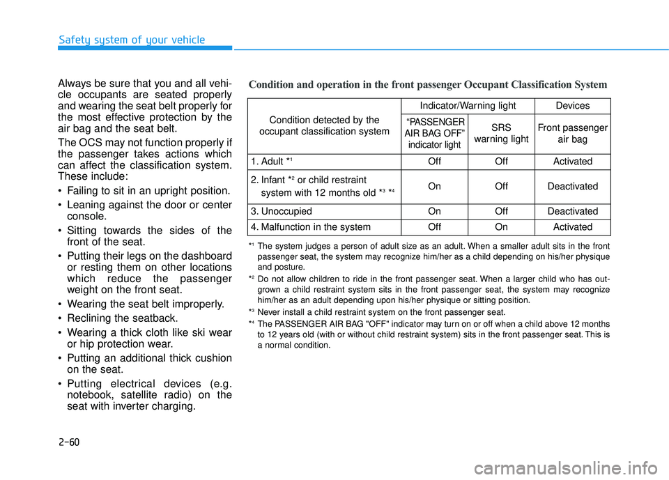
The OCS may not function properly if
the passenger takes actions which
can affect the classification system.These include:
Failing to sit in an upright position.
Leaning against the door or centerconsole.
Sitting towards the sides of the front of the seat.
Putting their legs on the dashboard or resting them on other locations which reduce the passenger
weight on the front seat.
Wearing the seat belt improperly.
Reclining the seatback.
Wearing a thick cloth like ski wear or hip protection wear.
Putting an additional thick cushion on the seat.
Putting electrical devices (e.g. notebook, satellite radio) on the
seat with inverter charging.Condition and operation in the front passenger Occupant Classification System
Condition detected by the
occupant classification system
Indicator/Warning lightDevices
“PASSENGER
AIR BAG OFF”
indicator lightSRS
warning lightFront passenger
air bag
1. Adult * 1OffOffActivated
2. Infant * 2
or child restraint
system with 12 months old * 3
*4 OnOffDeactivated
3. Unoccupied OnOffDeactivated
4. Malfunction in the systemOffOnActivated
*
1
The system judges a person of adult size as an adult. When a smaller adult sits in the front
passenger seat, the system may recognize him/her as a child depending on his/her physique
and posture.
* 2
Do not allow children to ride in the front passenger seat. When a larger child who has out-
grown a child restraint system sits in the front passenger seat, the system may recognize
him/her as an adult depending upon his/her physique or sitting position.
* 3
Never install a child restraint system on the front passenger seat.
* 4
The PASSENGER AIR BAG "OFF" indicator may turn on or off when a child above 12 months
to 12 years old (with or without child restraint system) sits in the front passenger seat. This is
a normal condition.
Page 196 of 642
3-98
Convenient features of your vehicle
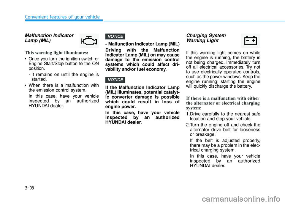
Malfunction IndicatorLamp (MIL)
This warning light illuminates:
Once you turn the ignition switch or Engine Start/Stop button to the ON position.
- It remains on until the engine isstarted.
When there is a malfunction with the emission control system.
In this case, have your vehicle
inspected by an authorized
HYUNDAI dealer. - Malfunction Indicator Lamp (MIL) Driving with the Malfunction
Indicator Lamp (MIL) on may cause
damage to the emission control
systems which could affect dri-
vability and/or fuel economy. If the Malfunction Indicator Lamp
(MIL) illuminates, potential catalyt-
ic converter damage is possible
which could result in loss of
engine power.
In this case, have your vehicle
inspected by an authorized
HYUNDAI dealer.
Charging System
Warning Light
If this warning light comes on while
the engine is running, the battery is
not being charged. Immediately turn
off all electrical accessories. Try not
to use electrically operated controls,
such as the power windows. Keep the
engine running; starting the engine
will quickly discharge the battery.
If there is a malfunction with either
the alternator or electrical charging
system:
1.Drive carefully to the nearest safe location and stop your vehicle.
2.Turn the engine off and check the alternator drive belt for looseness
or breakage.
If the belt is adjusted properly,
there may be a problem in the elec-
trical charging system.
In this case, have your vehicle
inspected by an authorized
HYUNDAI dealer.
NOTICE
NOTICE
Page 214 of 642
3-116
Convenient features of your vehicle
Do not leave the lamp switches on
for an extended period of time
when the engine is turned off.
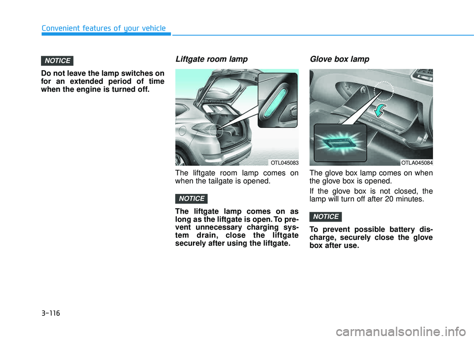
Liftgate room lamp
The liftgate room lamp comes onwhen the tailgate is opened. The liftgate lamp comes on as
long as the liftgate is open. To pre-
vent unnecessary charging sys-
tem drain, close the liftgate
securely after using the liftgate.
Glove box lamp
The glove box lamp comes on when
the glove box is opened.
If the glove box is not closed, the
lamp will turn off after 20 minutes.
To prevent possible battery dis-
charge, securely close the glove
box after use.
NOTICE
NOTICE
NOTICE
OTL045083OTLA045084
Page 275 of 642
4-12
Multimedia System
(Continued)
Some USB devices may not be sup- ported due to compatibility issues.
Avoid contact between the USB con- nector with bodily parts or foreign
objects.
Repeated connecting/disconnecting of USB devices within short periods
of time may result in product mal-
function.
A strange noise may occur when dis- connecting the USB.
Make sure to connect/disconnect external USB devices with the audio
power turned off.
The amount of time required to rec- ognize the USB device may differ
depending on the type, size or file
formats stored in the USB. Such dif-
ferences in time are not indications
of malfunctions.
The device only supports USB devices used to play music files.
USB images and videos are not sup- ported.
(Continued)(Continued)
Do not use the USB I/F to charge batteries or USB accessories that
generate heat. Such acts may lead to
worsened performance or damage
to the device.
The device may not recognize the USB device if separately purchased
USB hubs and extension cables are
being used. Connect the USB direct-
ly with the multimedia terminal of
the vehicle.
When using mass storage USB devices with separate logical drives,
only files saved to the root drive can
be played.
Files may not properly operate if application programs are installed
to the USBs.
The device may not operate normal- ly if MP3 Players, cellular phones,
digital cameras, or other electronic
devices (USB devices not recognized
as portable disk drives) are connect-
ed with the device.
(Continued)(Continued)
Charging through the USB may not
work for some mobile devices.
The device may not support normal operation when using a USB memo-
ry type besides (Metal Cover Type)
USB Memory.
The device may not support normal operation when using formats such
as HDD Type, CF, or SD Memory.
The device will not support files locked by DRM (Digital Rights
Management.)
USB memory sticks used by con- necting an Adaptor (SD Type or CF
Type) may not be properly recog-
nized.
The device may not operate proper- ly when using USB HDDs or USBs
subject to connection failures
caused by vehicle vibrations. (e.g. i-
stick type)
(Continued)
Page 277 of 642
4-14
Multimedia System
(Continued)
If your iPhone
®is connected to both
the Bluetooth®Wireless Technology
and USB, the sound may not be
properly played. In your iPhone
®,
select the Dock c onnector or
Bluetooth
®Wireless Technology to
change the sound output (source).
iPod mode cannot be operated when the iPod
®cannot be recognized due
to versions that do not support com-
munication protocols.
For fifth generation iPod
®Nano
devices, the iPod®may not be recog-
nized when the battery level is low.
Please charge the iPod
®for use.
Search/play orders shown within the iPod
®device may differ with the
orders shown within the audio sys-
tem.
If the iPod
®malfunctions due to an
iPod®device defect, reset the iPod®
and try again. (To learn more, refer to
your iPod®manual)
(Continued) (Continued)
Some iPod
®s may not sync with the
System depending on its version. If
the Media is removed before the
Media is recognized, then the sys-
tem may not properly restore the
previously operated mode. (iPad
®
charging is not supported.)
Information - Using the AUX
device
If an external device connector is connected with the AUX terminal,
then AUX mode will automatically
operate. Once the connector is dis-
connected, the previous mode will
be restored.
AUX mode can be used only when an external audio player (cam-
corder, in-car DVD player, etc.) has
been connected.
The AUX volume can be controlled separately from other audio modes.
Connecting a connector jack to the AUX terminal without an external
device will convert the system to
AUX mode, but only output noise.
When an external device is not
being used, also remove the connec-
tor jack.
When the external device power is connected to the power jack, play-
ing the external device may output
noise. In such cases, disconnect the
power connection before use.
Fully insert the AUX cable to the AUX jack upon use.i
Page 391 of 642
5-7
Driving your vehicle
5
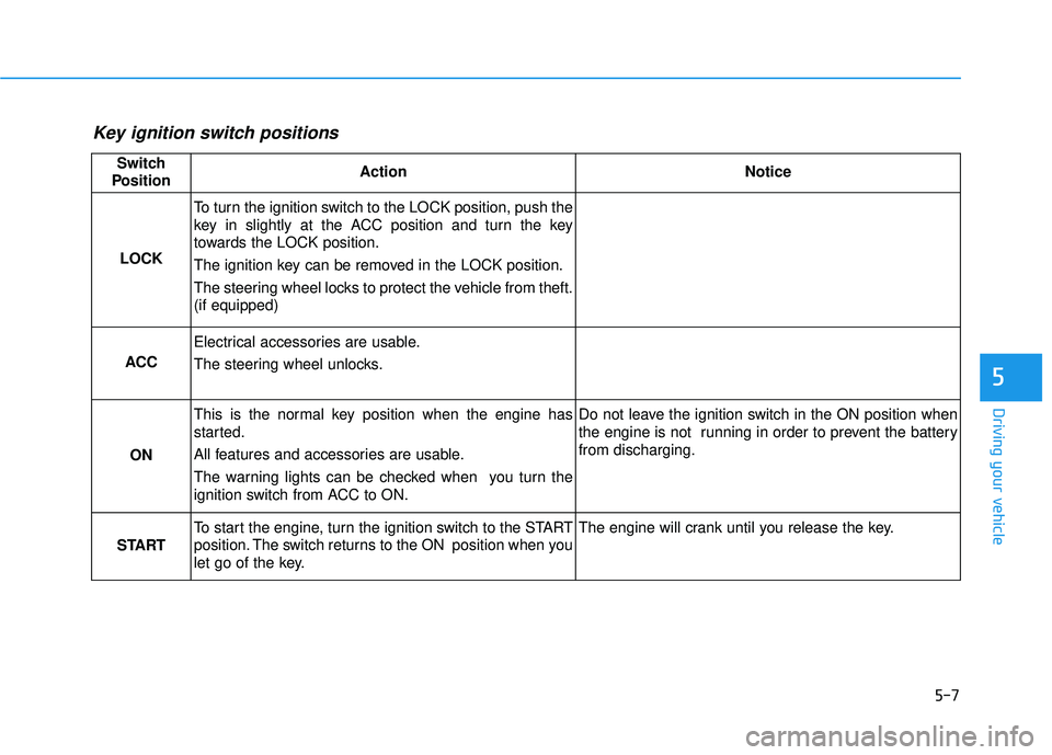
Key ignition switch positions
Switch
PositionActionNotice
LOCK
To turn the ignition switch to the LOCK position, push the
key in slightly at the ACC position and turn the key
towards the LOCK position.
The ignition key can be removed in the LOCK position.
The steering wheel locks to protect the vehicle from theft. (if equipped)
ACC
Electrical accessories are usable.
The steering wheel unlocks.
ON
This is the normal key position when the engine has
started.
All features and accessories are usable.
The warning lights can be checked when you turn the
ignition switch from ACC to ON.Do not leave the ignition switch in the ON position when
the engine is not running in order to prevent the battery from discharging.
START
To start the engine, turn the ignition switch to the START
position. The switch returns to the ON position when you
let go of the key.The engine will crank until you release the key.
Page 394 of 642
5-10
Driving your vehicle
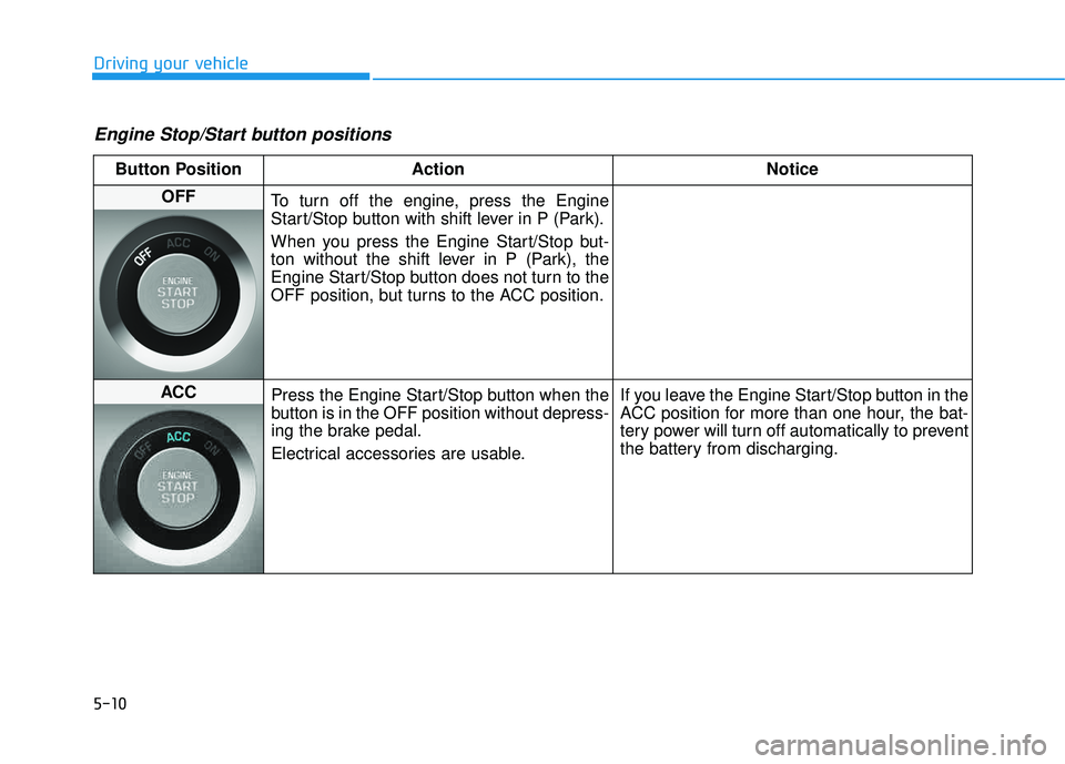
Engine Stop/Start button positions
Button Position ActionNotice
OFF
To turn off the engine, press the Engine
Start/Stop button with shift lever in P (Park).
When you press the Engine Start/Stop but-
ton without the shift lever in P (Park), the
Engine Start/Stop button does not turn to the
OFF position, but turns to the ACC position.
ACC Press the Engine Start/Stop button when the
button is in the OFF position without depress-
ing the brake pedal.
Electrical accessories are usable. If you leave the Engine Start/Stop button in the
ACC position for more than one hour, the bat-
tery power will turn off automatically to prevent
the battery from discharging.
Page 395 of 642
5-11
Driving your vehicle
5
Button Position ActionNotice
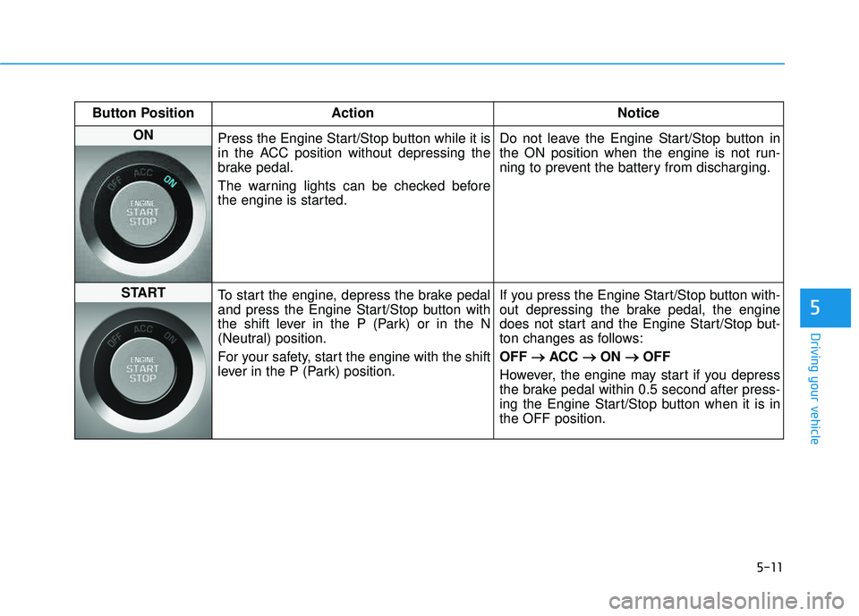
ON
Press the Engine Start/Stop button while it is
in the ACC position without depressing the
brake pedal.
The warning lights can be checked before
the engine is started. Do not leave the Engine Start/Stop button in
the ON position when the engine is not run-
ning to prevent the battery from discharging.
START
To start the engine, depress the brake pedal
and press the Engine Start/Stop button with
the shift lever in the P (Park) or in the N
(Neutral) position.
For your safety, start the engine with the shift
lever in the P (Park) position. If you press the Engine Start/Stop button with-
out depressing the brake pedal, the engine
does not start and the Engine Start/Stop but-
ton changes as follows: OFF
�
�
ACC ��
ON ��
OFF
However, the engine may start if you depress
the brake pedal within 0.5 second after press-
ing the Engine Start/Stop button when it is inthe OFF position.
Page 493 of 642
6-6
What to do in an emergency
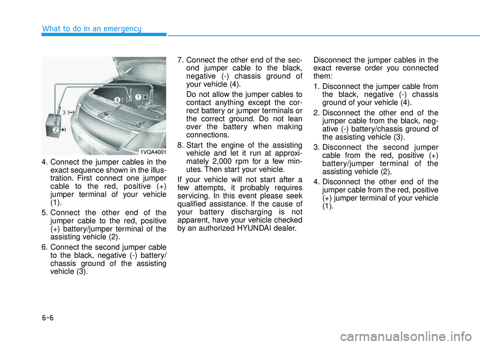
4. Connect the jumper cables in theexact sequence shown in the illus-
tration. First connect one jumper
cable to the red, positive (+)
jumper terminal of your vehicle(1).
5. Connect the other end of the jumper cable to the red, positive
(+) battery/jumper terminal of the
assisting vehicle (2).
6. Connect the second jumper cable to the black, negative (-) battery/
chassis ground of the assisting
vehicle (3). 7. Connect the other end of the sec-
ond jumper cable to the black,
negative (-) chassis ground of
your vehicle (4).
Do not allow the jumper cables to
contact anything except the cor-
rect battery or jumper terminals or
the correct ground. Do not lean
over the battery when making
connections.
8. Start the engine of the assisting vehicle and let it run at approxi-
mately 2,000 rpm for a few min-
utes. Then start your vehicle.
If your vehicle will not start after a
few attempts, it probably requires
servicing. In this event please seek
qualified assistance. If the cause of
your battery discharging is not
apparent, have your vehicle checked
by an authorized HYUNDAI dealer. Disconnect the jumper cables in the
exact reverse order you connectedthem:
1. Disconnect the jumper cable from
the black, negative (-) chassis
ground of your vehicle (4).
2. Disconnect the other end of the jumper cable from the black, neg-
ative (-) battery/chassis ground of
the assisting vehicle (3).
3. Disconnect the second jumper cable from the red, positive (+)
battery/jumper terminal of the
assisting vehicle (2).
4. Disconnect the other end of the jumper cable from the red, positive
(+) jumper terminal of your vehicle(1).
1VQA4001