tow HYUNDAI VELOSTER TURBO 2016 User Guide
[x] Cancel search | Manufacturer: HYUNDAI, Model Year: 2016, Model line: VELOSTER TURBO, Model: HYUNDAI VELOSTER TURBO 2016Pages: 406, PDF Size: 7.83 MB
Page 124 of 406
447
Features of your vehicle
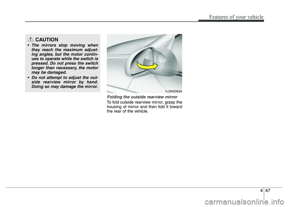
Folding the outside rearview mirror
To fold outside rearview mirror, grasp the
housing of mirror and then fold it toward
the rear of the vehicle.
1LDA2083A
CAUTION
• The mirrors stop moving when
they reach the maximum adjust-
ing angles, but the motor contin-
ues to operate while the switch is
pressed. Do not press the switch
longer than necessary, the motor
may be damaged.
• Do not attempt to adjust the out-
side rearview mirror by hand.
Doing so may damage the mirror.
Page 129 of 406
Features of your vehicle
52 4
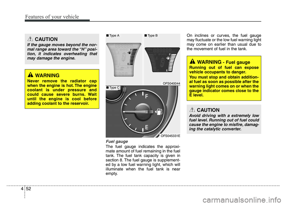
Fuel gauge
The fuel gauge indicates the approxi-
mate amount of fuel remaining in the fuel
tank.
The fuel tank capacity is given in
section 8.The fuel gauge is supplement-
ed by a low fuel warning light, which will
illuminate when the fuel tank is near
empty.On inclines or curves, the fuel gauge
may fluctuate or the low fuel warning light
may come on earlier than usual due to
the movement of fuel in the tank.
WARNING- Fuel gauge
Running out of fuel can expose
vehicle occupants to danger.
You must stop and obtain addition-
al fuel as soon as possible after the
warning light comes on or when the
gauge indicator comes close to the
E level.
CAUTION
Avoid driving with a extremely low
fuel level. Running out of fuel could
cause the engine to misfire, damag-
ing the catalytic converter.
CAUTION
If the gauge moves beyond the nor-
mal range area toward the “H” posi-
tion, it indicates overheating that
may damage the engine.
WARNING
Never remove the radiator cap
when the engine is hot. The engine
coolant is under pressure and
could cause severe burns. Wait
until the engine is cool before
adding coolant to the reservoir.OFS040044
OFS045331E
■Type A■Type B
■Type C
Page 142 of 406
465
Features of your vehicle
Parking brake & brake fluid
warning light
Parking brake warning
This light is illuminated when the parking
brake is applied with the ignition switch in
the START or ON position. The warning
light should go off when the parking
brake is released.
Low brake fluid level warning
If the warning light remains on, it may
indicate that the brake fluid level in the
reservoir is low.
If the warning light remains on:
1. Drive carefully to the nearest safe
location and stop your vehicle.
2. With the engine stopped, check the
brake fluid level immediately and add
fluid as required. Then check all brake
components for fluid leaks.
3. Do not drive the vehicle if leaks are
found, the warning light remains on or
the brakes do not operate properly.
Have the vehicle towed to any author-
ized HYUNDAI dealer for a brake sys-
tem inspection and necessary repairs.Your vehicle is equipped with a dual-
diagonal braking system. This means you
still have braking on two wheels even if
one of the brake circuits is damaged or
malfunctions. With only one of the circuits
working, more than normal pedal travel
and greater pedal pressure are required
to stop the car. Also, the car will not stop
in as short a distance with only a portion
of the brake system working. If the
brakes fail while you are driving, shift to a
lower gear for additional engine braking
and stop the car as soon as it is safe to
do so.
To check bulb operation, check whether
the parking brake and brake fluid warning
light illuminates when the ignition switch
is in the ON position.
Low tire pressure telltale
(if equipped)
The low tire pressure telltale illuminates
when one or more of your tires is signifi-
cantly underinflated.
Inflate your tires to the correct inflation
pressure.
The low tire pressure telltale will illumi-
nate after it blinks for approximately one
minute when there is a problem with the
Tire Pressure Monitoring System.
If this occurs, have the system checked
by an authorized HYUNDAI dealer as
soon as possible.
For details, refer to the TPMS on chapter 6.
WARNING
Driving the vehicle with a warning
light on is dangerous. If the brake
warning light remains on, have the
brakes checked and repaired imme-
diately by an authorized HYUNDAI
dealer.
WARNING - Low tire pres-
sure
Significantly low tire pressure
makes the vehicle unstable and can
contribute to loss of vehicle control
and increased braking distances.
Continued driving on tires with low
pressure will cause the tires to
overheat and fail.
Page 156 of 406
479
Features of your vehicle
• The sensing distance while the rear
parking assist system is in operation is
approximately 120 cm (47 in.).
• When more than two objects are
sensed at the same time, the closest
one will be recognized first.Types of warning sound
• When an object is 120 cm to 81 cm (47
in. to 32 in.) from the rear bumper:
Buzzer beeps intermittently
• When an object is 80 cm to 41 cm (31
in. to 16 in.) from the rear bumper:
Buzzer beeps more frequently
• When an object is within 40 cm (15 in.)
of the rear bumper:
Buzzer sounds continuously.
Non-operational conditions of
rear parking assist system
The rear parking assist system may
not operate properly when:
1. Moisture is frozen to the sensor. (It will
operate normally when the moisture
has been cleared.)
2. The sensor is covered with foreign
matter, such as snow or water, or the
sensor cover is blocked. (It will operate
normally when the material is removed
or the sensor is no longer blocked.)
3. Driving on uneven road surfaces
(unpaved roads, gravel, bumps, gradi-
ent).
4. Objects generating excessive noise
(vehicle horns, loud motorcycle
engines, or truck air brakes) are within
range of the sensor.
5. Heavy rain or water spray exists.
6. Wireless transmitters or mobile
phones are within range of the sensor.
7. Trailer towing.
Page 163 of 406
Features of your vehicle
86 4
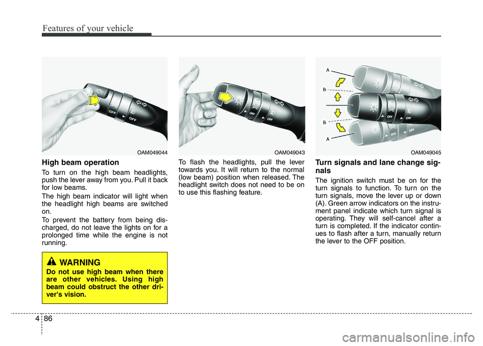
High beam operation
To turn on the high beam headlights,
push the lever away from you. Pull it back
for low beams.
The high beam indicator will light when
the headlight high beams are switched
on.
To prevent the battery from being dis-
charged, do not leave the lights on for a
prolonged time while the engine is not
running.To flash the headlights, pull the lever
towards you. It will return to the normal
(low beam) position when released. The
headlight switch does not need to be on
to use this flashing feature.
Turn signals and lane change sig-
nals
The ignition switch must be on for the
turn signals to function. To turn on the
turn signals, move the lever up or down
(A). Green arrow indicators on the instru-
ment panel indicate which turn signal is
operating. They will self-cancel after a
turn is completed. If the indicator contin-
ues to flash after a turn, manually return
the lever to the OFF position.
OAM049043OAM049044
WARNING
Do not use high beam when there
are other vehicles. Using high
beam could obstruct the other dri-
ver's vision.
OAM049045
Page 166 of 406
489
Features of your vehicle
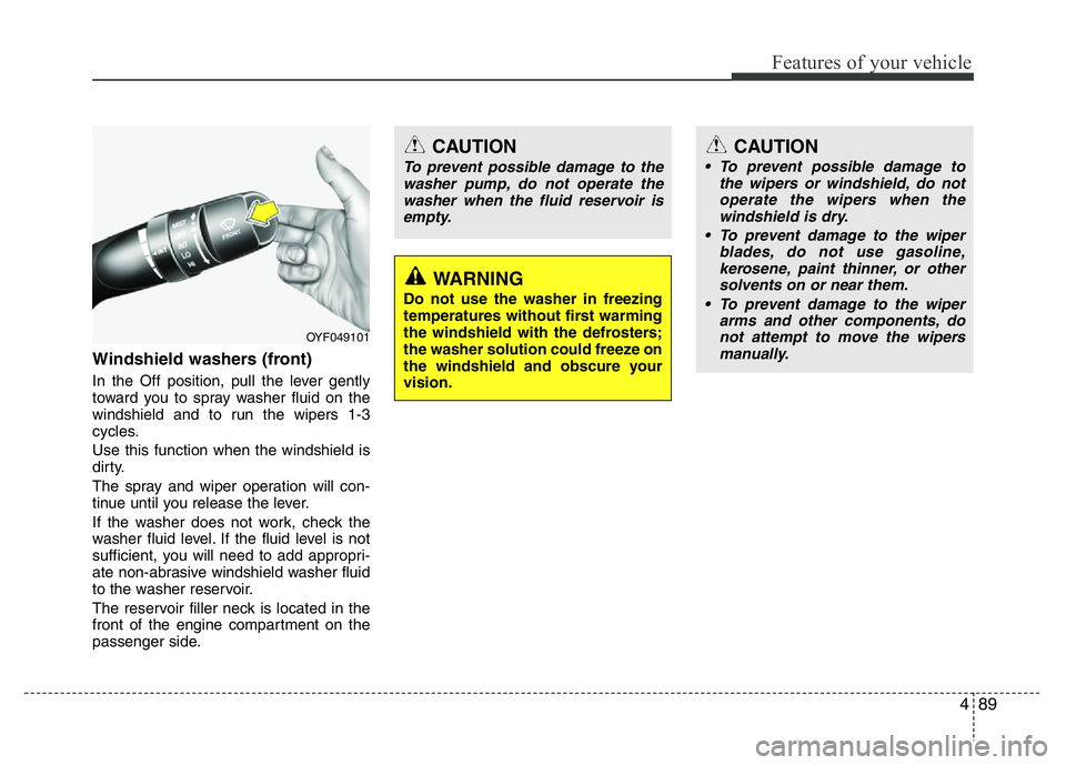
Windshield washers (front)
In the Off position, pull the lever gently
toward you to spray washer fluid on the
windshield and to run the wipers 1-3
cycles.
Use this function when the windshield is
dirty.
The spray and wiper operation will con-
tinue until you release the lever.
If the washer does not work, check the
washer fluid level. If the fluid level is not
sufficient, you will need to add appropri-
ate non-abrasive windshield washer fluid
to the washer reservoir.
The reservoir filler neck is located in the
front of the engine compartment on the
passenger side.
OYF049101
WARNING
Do not use the washer in freezing
temperatures without first warming
the windshield with the defrosters;
the washer solution could freeze on
the windshield and obscure your
vision.
CAUTION
To prevent possible damage to the
washer pump, do not operate the
washer when the fluid reservoir is
empty.
CAUTION
• To prevent possible damage to
the wipers or windshield, do not
operate the wipers when the
windshield is dry.
• To prevent damage to the wiper
blades, do not use gasoline,
kerosene, paint thinner, or other
solvents on or near them.
• To prevent damage to the wiper
arms and other components, do
not attempt to move the wipers
manually.
Page 174 of 406
497
Features of your vehicle
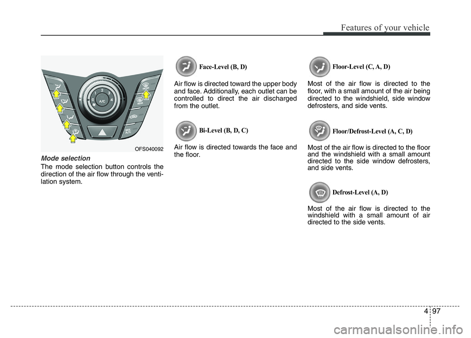
Mode selection
The mode selection button controls the
direction of the air flow through the venti-
lation system.
Face-Level (B, D)
Air flow is directed toward the upper body
and face. Additionally, each outlet can be
controlled to direct the air discharged
from the outlet.
Bi-Level (B, D, C)
Air flow is directed towards the face and
the floor.
Floor-Level (C, A, D)
Most of the air flow is directed to the
floor, with a small amount of the air being
directed to the windshield, side window
defrosters, and side vents.
Floor/Defrost-Level (A, C, D)
Most of the air flow is directed to the floor
and the windshield with a small amount
directed to the side window defrosters,
and side vents.
Defrost-Level (A, D)
Most of the air flow is directed to the
windshield with a small amount of air
directed to the side vents.
OFS040092
Page 175 of 406
Features of your vehicle
98 4
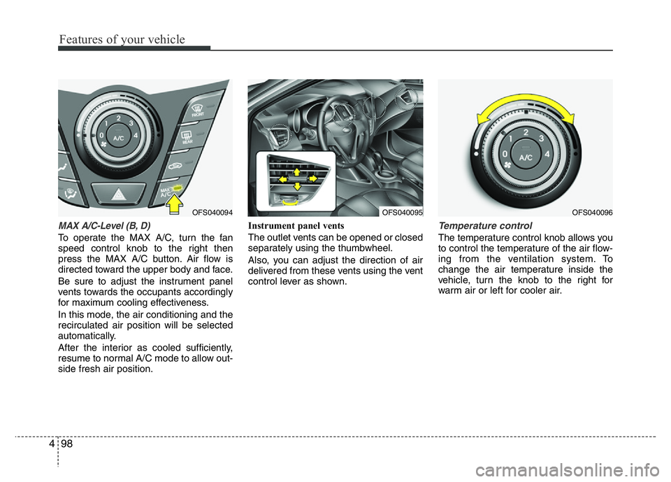
MAX A/C-Level (B, D)
To operate the MAX A/C, turn the fan
speed control knob to the right then
press the MAX A/C button. Air flow is
directed toward the upper body and face.
Be sure to adjust the instrument panel
vents towards the occupants accordingly
for maximum cooling effectiveness.
In this mode, the air conditioning and the
recirculated air position will be selected
automatically.
After the interior as cooled sufficiently,
resume to normal A/C mode to allow out-
side fresh air position.Instrument panel vents
The outlet vents can be opened or closed
separately using the thumbwheel.
Also, you can adjust the direction of air
delivered from these vents using the vent
control lever as shown.
Temperature control
The temperature control knob allows you
to control the temperature of the air flow-
ing from the ventilation system. To
change the air temperature inside the
vehicle, turn the knob to the right for
warm air or left for cooler air.
OFS040095OFS040096OFS040094
Page 184 of 406
4107
Features of your vehicle
Face-Level
Air flow is directed toward the upper body
and face. Additionally, each outlet can be
controlled to direct the air discharged
from the outlet.
Bi-Level
Air flow is directed towards the face and
the floor.
Floor-Level
Most of the air flow is directed to the
floor, with a small amount of the air being
directed to the windshield and side win-
dow defrosters.
Floor/Defrost-Level
Most of the air flow is directed to the floor
and the windshield with a small amount
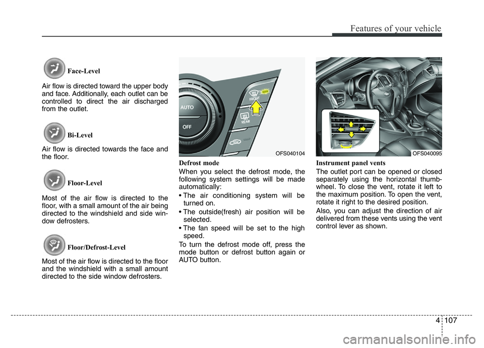
directed to the side window defrosters.Defrost mode
When you select the defrost mode, the
following system settings will be made
automatically:
• The air conditioning system will be
turned on.
• The outside(fresh) air position will be
selected.
• The fan speed will be set to the high
speed.
To turn the defrost mode off, press the
mode button or defrost button again or
AUTO button.Instrument panel vents
The outlet port can be opened or closed
separately using the horizontal thumb-
wheel. To close the vent, rotate it left to
the maximum position. To open the vent,
rotate it right to the desired position.
Also, you can adjust the direction of air
delivered from these vents using the vent
control lever as shown.
OFS040095OFS040104
Page 192 of 406
4115
Features of your vehicle
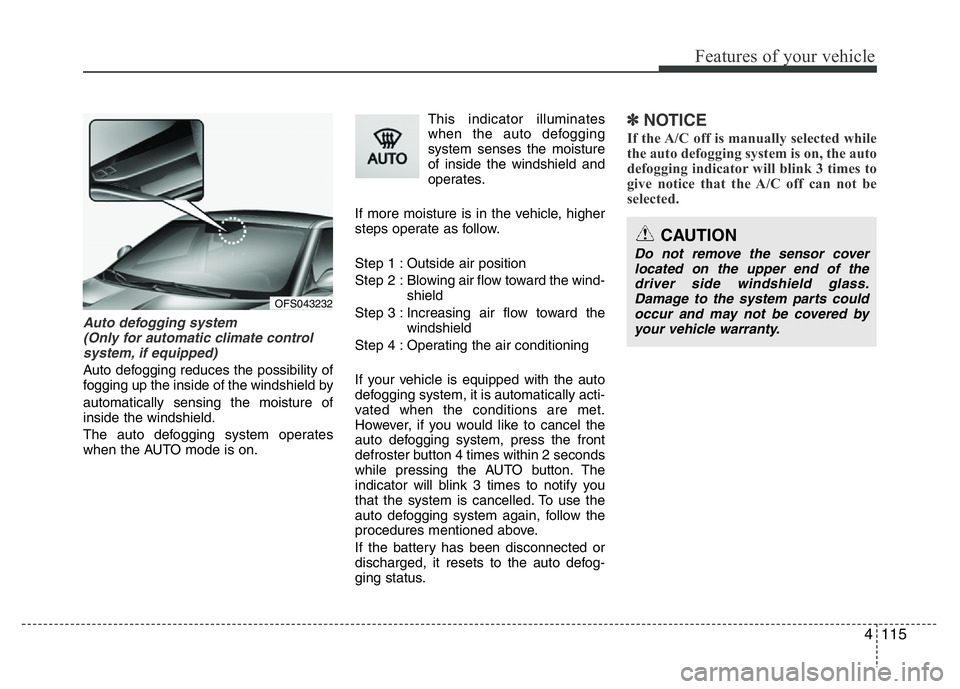
Auto defogging system
(Only for automatic climate control
system, if equipped)
Auto defogging reduces the possibility of
fogging up the inside of the windshield by
automatically sensing the moisture of
inside the windshield.
The auto defogging system operates
when the AUTO mode is on.This indicator illuminates
when the auto defogging
system senses the moisture
of inside the windshield and
operates.
If more moisture is in the vehicle, higher
steps operate as follow.
Step 1 : Outside air position
Step 2 : Blowing air flow toward the wind-
shield
Step 3 : Increasing air flow toward the
windshield
Step 4 : Operating the air conditioning
If your vehicle is equipped with the auto
defogging system, it is automatically acti-
vated when the conditions are met.
However, if you would like to cancel the
auto defogging system, press the front
defroster button 4 times within 2 seconds
while pressing the AUTO button. The
indicator will blink 3 times to notify you
that the system is cancelled. To use the
auto defogging system again, follow the
procedures mentioned above.
If the battery has been disconnected or
discharged, it resets to the auto defog-
ging status.
✽NOTICE
If the A/C off is manually selected while
the auto defogging system is on, the auto
defogging indicator will blink 3 times to
give notice that the A/C off can not be
selected.
OFS043232
CAUTION
Do not remove the sensor cover
located on the upper end of the
driver side windshield glass.
Damage to the system parts could
occur and may not be covered by
your vehicle warranty.