bat fl INFINITI FX35 2004 Repair Manual
[x] Cancel search | Manufacturer: INFINITI, Model Year: 2004, Model line: FX35, Model: INFINITI FX35 2004Pages: 4449, PDF Size: 99.66 MB
Page 720 of 4449

NAVIGATION SYSTEM
AV-129
C
D
E
F
G
H
I
J
L
MA
B
AV
Revision: 2004 November 2004 FX35/FX45
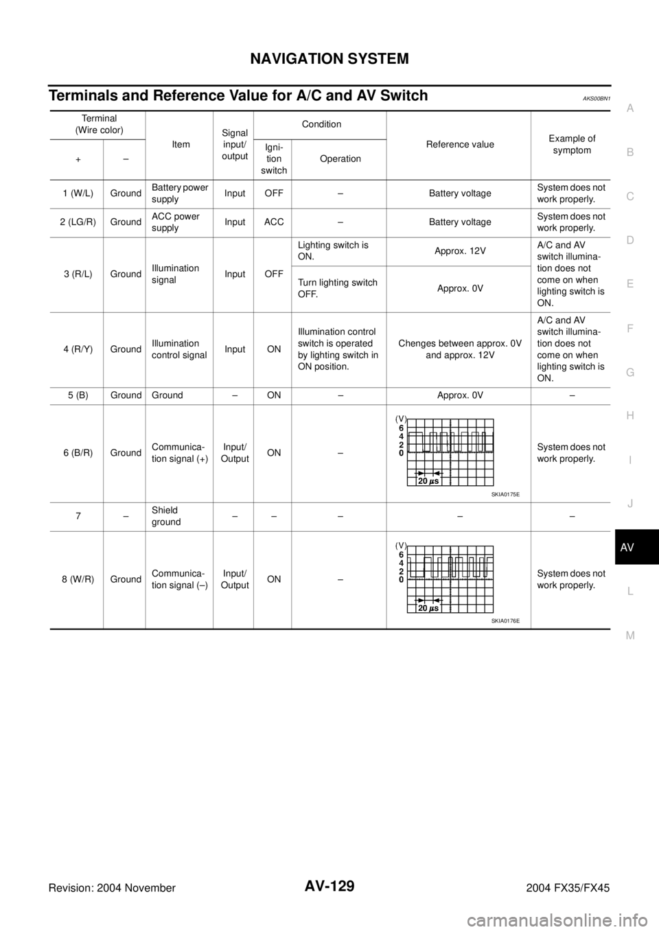
Terminals and Reference Value for A/C and AV SwitchAKS00BN1
Te r m i n a l
(Wire color)
ItemSignal
input/
outputCondition
Reference valueExample of
symptom
+–Igni-
tion
switchOperation
1 (W/L) GroundBattery power
supplyInput OFF – Battery voltageSystem does not
work properly.
2 (LG/R) GroundACC power
supplyInput ACC – Battery voltageSystem does not
work properly.
3 (R/L) GroundIllumination
signal Input OFFLighting switch is
ON.Approx. 12VA/C and AV
switch illumina-
tion does not
come on when
lighting switch is
ON. Turn lighting switch
OFF.Approx. 0V
4 (R/Y) GroundIllumination
control signalInput ONIllumination control
switch is operated
by lighting switch in
ON position.Chenges between approx. 0V
and approx. 12V A/C and AV
switch illumina-
tion does not
come on when
lighting switch is
ON.
5 (B) Ground Ground – ON – Approx. 0V –
6 (B/R) GroundCommunica-
tion signal (+)Input/
OutputON –System does not
work properly.
7–Shield
ground –– – – –
8 (W/R) GroundCommunica-
tion signal (–)Input/
OutputON –System does not
work properly.
SKIA0175E
SKIA0176E
Page 736 of 4449

NAVIGATION SYSTEM
AV-145
C
D
E
F
G
H
I
J
L
MA
B
AV
Revision: 2004 November 2004 FX35/FX45
Power Supply and Ground Circuit Check for NAVI Control UnitAKS00BN7
1. CHECK FUSE
Make sure that the following fuses of the NAVI control unit are not blown.
OK or NG
OK >> GO TO 2.
NG >> If fuse is blown, be sure to eliminate case of malfunction before installing new fuse. Refer to PG-3,
"POWER SUPPLY ROUTING CIRCUIT" .
2. CHECK POWER SUPPLY CIRCUIT
1. Check voltage between NAVI control unit harness connector ter-
minals and ground.
OK or NG
OK >> GO TO 3.
NG >> Repair harness or connector.
3. CHECK GROUND CIRCUIT
1. Turn ignition switch OFF.
2. Disconnect NAVI control unit connector.
3. Check continuity between NAVI control unit harness connector
B208 terminals 1 (B), 4 (B) and ground.
OK or NG
OK >> INSPECTION END
NG >> Repair harness or connector.
Unit Signal Fuse No.
NAVI control unitBattery power supply 32
ACC power supply 6
Terminals Ignition switch position
(+)
(–) OFF ACC ON
ConnectorTerminal
(Wire color)
B2082 (Y), 3 (Y)
GroundBattery
voltageBattery
voltageBattery
voltage
6 (LG) 0VBattery
voltageBattery
voltage
SKIA8932E
1, 4 – Ground : Continuity should exist.
PKIA2853E
Page 737 of 4449

AV-146
NAVIGATION SYSTEM
Revision: 2004 November 2004 FX35/FX45
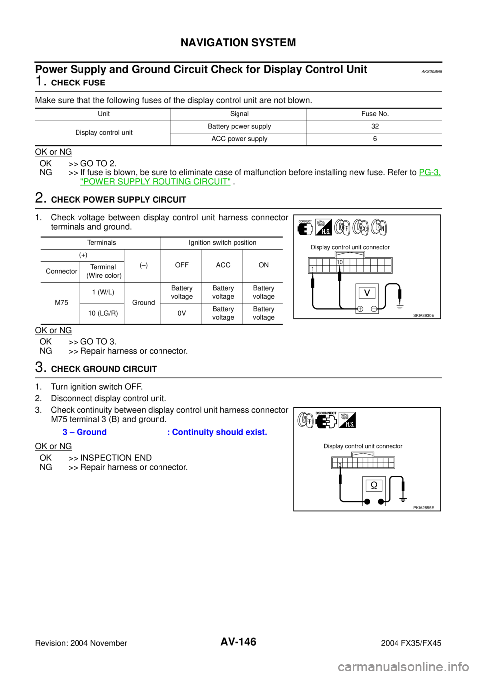
Power Supply and Ground Circuit Check for Display Control UnitAKS00BN8
1. CHECK FUSE
Make sure that the following fuses of the display control unit are not blown.
OK or NG
OK >> GO TO 2.
NG >> If fuse is blown, be sure to eliminate case of malfunction before installing new fuse. Refer to PG-3,
"POWER SUPPLY ROUTING CIRCUIT" .
2. CHECK POWER SUPPLY CIRCUIT
1. Check voltage between display control unit harness connector
terminals and ground.
OK or NG
OK >> GO TO 3.
NG >> Repair harness or connector.
3. CHECK GROUND CIRCUIT
1. Turn ignition switch OFF.
2. Disconnect display control unit.
3. Check continuity between display control unit harness connector
M75 terminal 3 (B) and ground.
OK or NG
OK >> INSPECTION END
NG >> Repair harness or connector.
Unit Signal Fuse No.
Display control unitBattery power supply 32
ACC power supply 6
Terminals Ignition switch position
(+)
(–) OFF ACC ON
ConnectorTerminal
(Wire color)
M751 (W/L)
GroundBattery
voltageBattery
voltageBattery
voltage
10 (LG/R) 0VBattery
voltageBattery
voltage
SKIA8930E
3 – Ground : Continuity should exist.
PKIA2855E
Page 740 of 4449

NAVIGATION SYSTEM
AV-149
C
D
E
F
G
H
I
J
L
MA
B
AV
Revision: 2004 November 2004 FX35/FX45
Power Supply and Ground Circuit Check for A/C and AV SwitchAKS00BNA
1. CHECK FUSE
Make sure that the following fuses of the A/C and AV switch are not blown.
OK or NG
OK >> GO TO 2.
NG >> If fuse is blown, be sure to eliminate case of malfunction before installing new fuse. Refer to PG-3,
"POWER SUPPLY ROUTING CIRCUIT" .
2. CHECK POWER SUPPLY CIRCUIT
1. Check voltage between AC and AV switch harness connector
terminals and ground.
OK or NG
OK >> GO TO 3.
NG >> Repair harness or connector.
3. CHECK GROUND CIRCUIT
1. Turn ignition switch OFF.
2. Disconnect A/C and AV switch connector.
3. Check continuity between A/C and AV switch harness connector
M64 terminals 5 (B) and ground.
OK or NG
OK >> INSPECTION END
NG >> Repair harness or connector.
Vehicle Speed Signal Check for NAVI Control UnitAKS00BNB
1. VEHICLE SPEED OPERATION CHECK
Does speedmeter is operated normally?
YES or NO
YES >> GO TO 2.
NO >> Check combination meter trouble diagnosis. Refer to DI-13, "
Diagnosis Flow" .
Unit Signal Fuse No.
A/C and AV switchBattery power supply 32
ACC power supply 6
Terminals Ignition switch position
(+)
(–) OFF ACC ON
ConnectorTe r m i n a l
(Wire color)
M641 (W/L)
GroundBattery
voltageBattery
voltageBattery
voltage
2 (LG/R) 0VBattery
voltageBattery
voltage
SKIA8937E
5 – Ground : Continuity should exist.
SKIA8938E
Page 743 of 4449

AV-152
NAVIGATION SYSTEM
Revision: 2004 November 2004 FX35/FX45
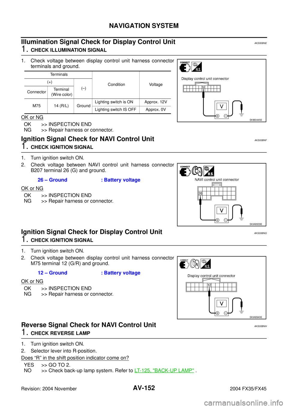
Illumination Signal Check for Display Control Unit AKS00BNE
1. CHECK ILLUMINATION SIGNAL
1. Check voltage between display control unit harness connector
terminals and ground.
OK or NG
OK >> INSPECTION END
NG >> Repair harness or connector.
Ignition Signal Check for NAVI Control UnitAKS00BNF
1. CHECK IGNITION SIGNAL
1. Turn ignition switch ON.
2. Check voltage between NAVI control unit harness connector
B207 terminal 26 (G) and ground.
OK or NG
OK >> INSPECTION END
NG >> Repair harness or connector.
Ignition Signal Check for Display Control UnitAKS00BNG
1. CHECK IGNITION SIGNAL
1. Turn ignition switch ON.
2. Check voltage between display control unit harness connector
M75 terminal 12 (G/R) and ground.
OK or NG
OK >> INSPECTION END
NG >> Repair harness or connector.
Reverse Signal Check for NAVI Control UnitAKS00BNH
1. CHECK REVERSE LAMP
1. Turn ignition switch ON.
2. Selector lever into R-position.
Does
“R” in the shift position indicator come on?
YES >> GO TO 2.
NO >> Check back-up lamp system. Refer to LT- 1 2 5 , "
BACK-UP LAMP" .
Terminals
Condition Voltage (+)
(–)
ConnectorTe r m i n a l
(Wire color)
M75 14 (R/L) GroundLighting switch is ON Approx. 12V
Lighting switch IS OFF Approx. 0V
SKIB0445E
26 – Ground : Battery voltage
SKIA8939E
12 – Ground : Battery voltage
SKIA8940E
Page 779 of 4449

AV-188
INFINITI MOBILE ENTERTAINMENT SYSTEM
Revision: 2004 November 2004 FX35/FX45
Terminals and Reference Value for DVD PlayerAKS00BOX
Terminal
(Wire color)
ItemSignal
input/
outputCondition
Reference valueExample of symp-
tom
(+) (-)Ignition
switchOperation
1 (L) 2 (R)MES output
signal (LH)
Output ACCRear AV
switch is ONNo sound
from speaker LH
3 (LG) 4 (PU)MES output
signal (RH)No sound
from speaker RH
8–Shield – – – – –
9
(Y/B)GroundAudio ON
signal (MES -
H/U) Output ACCPush “POWER”
switch of DVD
playerApprox. 5VSystem dose not
work properly
10
(R/Y)GroundIllumination
control signalInput OFFIllumination con-
trol switch is oper-
ated by lighting
switch in 1st posi-
tion.Changes between approx. 0 and
approx. 12V.DVD player illumi-
nation does not
come on then light-
ing switch is ON
11
(L/W)GroundControl sig-
nal (H/U -
MES)Input ACCPush “POWER”
switch of DVD
playerApprox. 5VSystem dose not
work properly
12
(R/L)GroundIllumination
signalInput OFFLighting switch is
ON (1st position).Approx. 12VDVD player illumi-
nation dose not
come on then light-
ing switch is ON Lighting switch
OFF.Approx. 0V
15
(LG/R)GroundACC power
supplyInput ACC – Battery voltageSystem does not
work properly
16
(W/L)GroundBattery
power supplyInput OFF – Battery voltageSystem dose not
work properly
17 (G) 19 (LG)MES output
signal (Com-
mon)Output ACCPlay CD or DVD
videoApprox. 0V –
18 (L) 19 (LG)MES output
signal (L+)Output ACCPlay CD or DVD
videoNo sound from
head phone LH
19 (LG) Ground Ground – ON – Approx. 0V –
20 (Y) 19 (LG)MES output
signal (R+)Output ACCPlay CD or DVD
videoNo sound from
head phone RH
21 (L) GroundACC power
supplyOutput ACC – Approx. 5VDisplay does not
work properly
22 (B) Ground Ground – ON – Approx. 0V –
SKIA0177E
SKIA5828E
SKIA5828E
Page 780 of 4449

INFINITI MOBILE ENTERTAINMENT SYSTEM
AV-189
C
D
E
F
G
H
I
J
L
MA
B
AV
Revision: 2004 November 2004 FX35/FX45
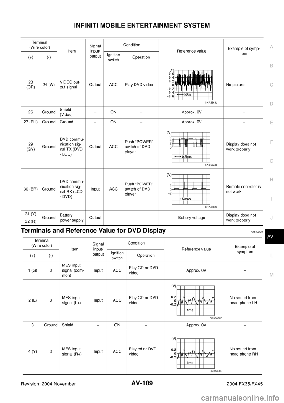
Terminals and Reference Value for DVD DisplayAKS00BOY
23
(OR)24 (W)VIDEO out-
put signalOutput ACC Play DVD video No picture
26 GroundShield
(Video)– ON – Approx. 0V –
27 (PU) Ground Ground – ON – Approx. 0V –
29
(GY)GroundDVD commu-
nication sig-
nal TX (DVD
- LCD)Output ACCPush “POWER”
switch of DVD
player Display does not
work properly
30 (BR) GroundDVD commu-
nication sig-
nal RX (LCD
- DVD)Input ACCPush “POWER”
switch of DVD
playerRemote controler is
not work
31 (Y)
GroundBattery
power supplyOutput – – Battery voltageDisplay dose not
work properly
32 (R)Terminal
(Wire color)
ItemSignal
input/
outputCondition
Reference valueExample of symp-
tom
(+) (-)Ignition
switchOperation
SKIA8863J
SKIB0322E
SKIA5832E
Te r m i n a l
(Wire color)
ItemSignal
input/
outputCondition
Reference valueExample of
symptom
(+) (-)Ignition
switchOperation
1 (G) 3MES input
signal (com-
mon)Input ACCPlay CD or DVD
videoApprox. 0V –
2 (L) 3MES input
signal (L+)Input ACCPlay CD or DVD
videoNo sound from
head phone LH
3 Ground Shield – ON – Approx. 0V –
4 (Y) 3MES input
signal (R+)Input ACCPlay cd or DVD
videoNo sound from
head phone RH
SKIA5828E
SKIA5828E
Page 781 of 4449

AV-190
INFINITI MOBILE ENTERTAINMENT SYSTEM
Revision: 2004 November 2004 FX35/FX45
5 (L) Ground Switch power Input ACC – Approx. 5VDisplay does not
work properly
6 (LG) Ground Ground – ON – Approx. 0V –
7 (OR) 8 (W)VIDEO input
signal Input ACC Play DVD video No picture
9 GroundShield
(Video)– ON – Approx. 0V –
10 (G) GroundShield (MES
data)– ON – Approx. 0V –
12 (PU) Ground Ground – ON – Approx. 0V –
13 (GY) 10 (G)DVD commu-
nication sig-
nal RX (DVD
- LCD)Input ACCPush “POWER”
switch of DVD
playerDisplay does not
work properly
14 (BR) 10 (G)DVD commu-
nication sig-
nal TX (LCD -
DVD)Output ACCPush “POWER”
switch of DVD
playerRemote con-
troler is not work
15 (Y)
GroundBattery
power supplyInput OFF – Battery voltageDisplay dose not
work properly
16 (R)Terminal
(Wire color)
ItemSignal
input/
outputCondition
Reference valueExample of
symptom
(+) (-)Ignition
switchOperation
SKIA8863J
SKIB0322E
SKIA5832E
Page 782 of 4449

INFINITI MOBILE ENTERTAINMENT SYSTEM
AV-191
C
D
E
F
G
H
I
J
L
MA
B
AV
Revision: 2004 November 2004 FX35/FX45
DVD Player Is Not WorkAKS00BOZ
1. CHECK FUSE
Make sure that the following fuse of the DVD player are not blown.
OK or NG
OK >> GO TO 2
NG >> If fuse is blown be sure to eliminate case of problem before installing new fuse, refer to PG-3,
"POWER SUPPLY ROUTING CIRCUIT" .
2. CHECK POWER SUPPLY CIRCUIT
Check voltage between DVD player harness connector terminals
and ground.
OK or NG
OK >> GO TO 3
NG >> Repair harness or connector.
3. CHECK GROUND CIRCUIT
1. Turn ignition switch OFF.
2. Disconnect DVD player connector.
3. Check continuity between the following DVD player harness
connector B19 terminal 22 (B) and ground.
OK or NG
OK >> GO TO 4.
NG >> Repair harness or connector.
Unit Signal Fuse NO.
DVD playerBattery power supply 32
ACC power supply 6
Terminals
Condition Voltage (+)
(-)
ConnectorTerminal
(Wire color)
M7316
(W/L)
GroundIgnition switch
OFFBattery voltage
15
(LG/R) Ignition switch
ACCBattery voltage
SKIB0323E
22 – Ground : Continuity should exist.
SKIA5846E
Page 784 of 4449

INFINITI MOBILE ENTERTAINMENT SYSTEM
AV-193
C
D
E
F
G
H
I
J
L
MA
B
AV
Revision: 2004 November 2004 FX35/FX45
Screen Is Not Shown (While Sounds Come Out of an Audio Speaker, Did not do
of a Head Phone)
AKS00BP0
1. CHECK POWER SUPPLY CIRCUIT
1. Check voltage between DVD player harness connector B19 ter-
minals 31 (Y), 32 (R) and ground.
2. Turn ignition switch ACC.
3. Check voltage between DVD player harness connector B19 ter-
minal 21 (L) and ground.
OK or NG
OK >> GO TO 2
NG >> Replace DVD player.
2. CHECK HARNESS
1. Turn ignition switch OFF.
2. Disconnect DVD display connector.
3. Check continuity between DVD player harness connector B19
terminals 21 (L), 31 (Y), 32 (R) and DVD display harness con-
nector B192 terminals 5 (L), 15 (Y), 16 (R).
4. Check continuity between DVD player harness connector B19
terminals 21 (L), 31 (Y), 32 (R) and ground.
5. Check continuity between DVD player harness connector B19
terminals 19 (LG), 27 (PU) and DVD display harness connector
B192 terminals 6 (LG), 12 (PU).
OK or NG
OK >> Replace DVD display.
NG >> Repair harness or connector.31, 32 – Ground : Battery voltage
SKIB0514E
21 – Ground : Approx. 5V
SKIA7021E
21 – 5 : Continuity should exist.
31 – 15 : Continuity should exist.
32 – 16 : Continuity should exist.
21, 31, 32 – Ground : Continuity should not exist.
19 – 6 : Continuity should exist.
27 – 12 : Continuity should exist.
SKIB0515E