height INFINITI FX35 2008 Owners Manual
[x] Cancel search | Manufacturer: INFINITI, Model Year: 2008, Model line: FX35, Model: INFINITI FX35 2008Pages: 3924, PDF Size: 81.37 MB
Page 3574 of 3924
RFD-32
< SERVICE INFORMATION >
REAR FINAL DRIVE ASSEMBLY
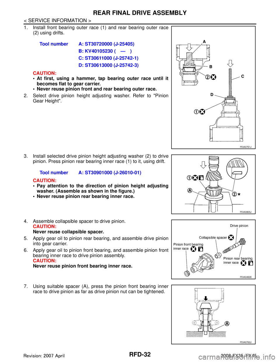
1. Install front bearing outer race (1) and rear bearing outer race(2) using drifts.
CAUTION:
At first, using a hammer, tap bearing outer race until it
becomes flat to gear carrier.
Never reuse pinion front and rear bearing outer race.
2. Select drive pinion height adjusting washer. Refer to "Pinion Gear Height".
3. Install selected drive pinion height adjusting washer (2) to drive pinion. Press pinion rear bearing inner race (1) to it, using drift.
CAUTION:
Pay attention to the direction of pinion height adjustingwasher. (Assemble as shown in the figure.)
Never reuse pinion rear bearing inner race.
4. Assemble collapsible spacer to drive pinion. CAUTION:
Never reuse collapsible spacer.
5. Apply gear oil to pinion rear bearing, and assemble drive pinion into gear carrier.
6. Apply gear oil to pinion front bearing, and assemble pinion front bearing inner race to drive pinion assembly.
CAUTION:
Never reuse pinion front bearing inner race.
7. Using suitable spacer (A), press the pinion front bearing inner race to drive pinion as far as drive pinion nut can be tightened.Tool number A: ST30720000 (J-25405)
B: KV40105230 ( — )
C: ST30611000 (J-25742-1)
D: ST30613000 (J-25742-3)
PDIA0761J
Tool number A: ST30901000 (J-26010-01)
PDIA0805J
PDIA0492E
PDIA0762J
3AA93ABC3ACD3AC03ACA3AC03AC63AC53A913A773A893A873A873A8E3A773A983AC73AC93AC03AC3
3A893A873A873A8F3A773A9D3AAF3A8A3A8C3A863A9D3AAF3A8B3A8C
Page 3581 of 3924
SERVICE DATA AND SPECIFICATIONS (SDS)
RFD-39
< SERVICE INFORMATION >
C EF
G H
I
J
K L
M A
B
RFD
N
O P
*: Always check with the Parts Department for the latest parts information.
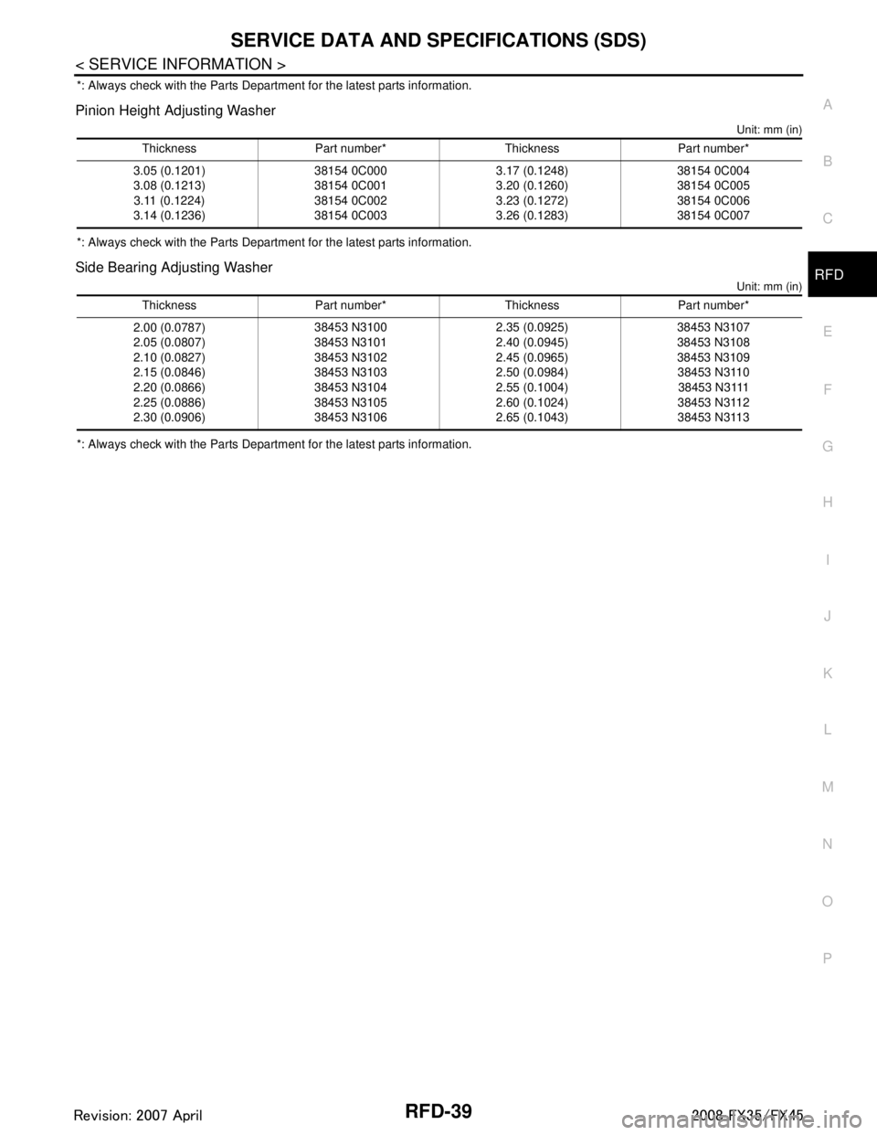
Pinion Height Adjusting Washer
Unit: mm (in)
*: Always check with the Parts Department for the latest parts information.
Side Bearing Adjusting Washer
Unit: mm (in)
*: Always check with the Parts Department for the latest parts information. Thickness Part number* Thickness Part number*
3.05 (0.1201)
3.08 (0.1213) 3.11 (0.1224)
3.14 (0.1236) 38154 0C000
38154 0C001
38154 0C002
38154 0C003 3.17 (0.1248)
3.20 (0.1260)
3.23 (0.1272)
3.26 (0.1283)38154 0C004
38154 0C005
38154 0C006
38154 0C007
Thickness Part number* Thickness Part number*
2.00 (0.0787)
2.05 (0.0807)
2.10 (0.0827)
2.15 (0.0846)
2.20 (0.0866)
2.25 (0.0886)
2.30 (0.0906) 38453 N3100
38453 N3101
38453 N3102
38453 N3103
38453 N3104
38453 N3105
38453 N3106 2.35 (0.0925)
2.40 (0.0945)
2.45 (0.0965)
2.50 (0.0984)
2.55 (0.1004)
2.60 (0.1024)
2.65 (0.1043)38453 N3107
38453 N3108
38453 N3109
38453 N3110 38453 N3111
38453 N3112
38453 N3113
3AA93ABC3ACD3AC03ACA3AC03AC63AC53A913A773A893A873A873A8E3A773A983AC73AC93AC03AC3
3A893A873A873A8F3A773A9D3AAF3A8A3A8C3A863A9D3AAF3A8B3A8C
Page 3582 of 3924

RSU-1
SUSPENSION
C
DF
G H
I
J
K L
M
SECTION RSU
A
B
RSU
N
O PCONTENTS
REAR SUSPENSION
SERVICE INFORMATION .. ..........................2
PRECAUTIONS .............................................. .....2
Cautions .............................................................. ......2
PREPARATION ...................................................3
Special Service Tool ........................................... ......3
Commercial Service Tool ..........................................3
NOISE, VIBRATION AND HARSHNESS
(NVH) TROUBLESHOOTING .............................
4
NVH Troubleshooting Chart ................................ ......4
REAR SUSPENSION ASSEMBLY .....................5
On-Vehicle Inspection and Service ..................... ......5
Wheel AlignmentInspection .......................................5
Removal and Installation ...........................................6
SHOCK ABSORBER ..........................................9
Removal and Installation ..................................... ......9
Disassembly and Assembly ......................................9
SUSPENSION ARM ..........................................11
Removal and Installation ..................................... ....11
RADIUS ROD ................................... .................13
Removal and Installation ..................................... ....13
FRONT LOWER LINK .......................................14
Removal and Installation .........................................14
REAR LOWER LINK & COIL SPRING .............15
Removal and Installation .........................................15
STABILIZER BAR .............................................16
Removal and Installation .........................................16
REAR SUSPENSION MEMBER .......................17
Removal and Installation ..................................... ....17
SERVICE DATA AND SPECIFICATIONS
(SDS) .................................................................
18
Wheel Alignment (Unladen*) ...................................18
Ball Joint ..................................................................18
Wheelarch Height (Unladen*) ..................................18
3AA93ABC3ACD3AC03ACA3AC03AC63AC53A913A773A893A873A873A8E3A773A983AC73AC93AC03AC3
3A893A873A873A8F3A773A9D3AAF3A8A3A8C3A863A9D3AAF3A8B3A8C
Page 3589 of 3924
RSU-8
< SERVICE INFORMATION >
REAR SUSPENSION ASSEMBLY
REMOVAL
1. Remove tires from vehicle with power tool.
2. Remove brake caliper with power tool. Hang it in a place where it will not interfere with work. Refer to BR-
24.
NOTE:
Avoid depressing brake pedal while brake caliper is removed.
3. Remove wheel sensor from rear final drive, t hen remove wheel sensor harness from rear suspension
member.
4. Remove height sensor harness from rear suspension member (if equipped).
5. Remove center muffler and main muffler. Refer to EX-3, "
Component".
6. Remove stabilizer bar. Refer to RSU-16, "
Removal and Installation".
7. Remove rear propeller shaft. Refer to PR-9, "
Removal and Installation".
8. Separate attachments between parking brake cable and vehicle and rear suspension member.
9. Remove rear lower link and coil spring. Refer to RSU-14, "
Removal and Installation".
10. Remove fixing bolt in lower side of shock absorber with power tool.
11. Set jack under rear final drive.
12. Remove fixing bolts and nuts of tunnel stay and mem ber stay with power tool, then remove those parts
from vehicle.
13. Remove fixing bolts and nuts of rear pin stay with pow er tool and then remove rear pin stay from vehicle.
14. Gradually lowering jack, remove rear suspension assembly.
INSTALLATION
Refer to "Removal and installation" for tightening torque. Install in the reverse order of removal.
NOTE:
Refer to component parts location and do not reuse non-reusable parts.
Perform final tightening of installation position of links (rubber bushing) under unladen conditions with tires on level ground. Check wheel alignment. Refer to RSU-5, "
Wheel AlignmentInspection".
After adjusting wheel alignment, adjust neutral position of steering angle sensor. Refer to BRC-8, "
Adjust-
ment of Steering Angle Sensor Neutral Position".
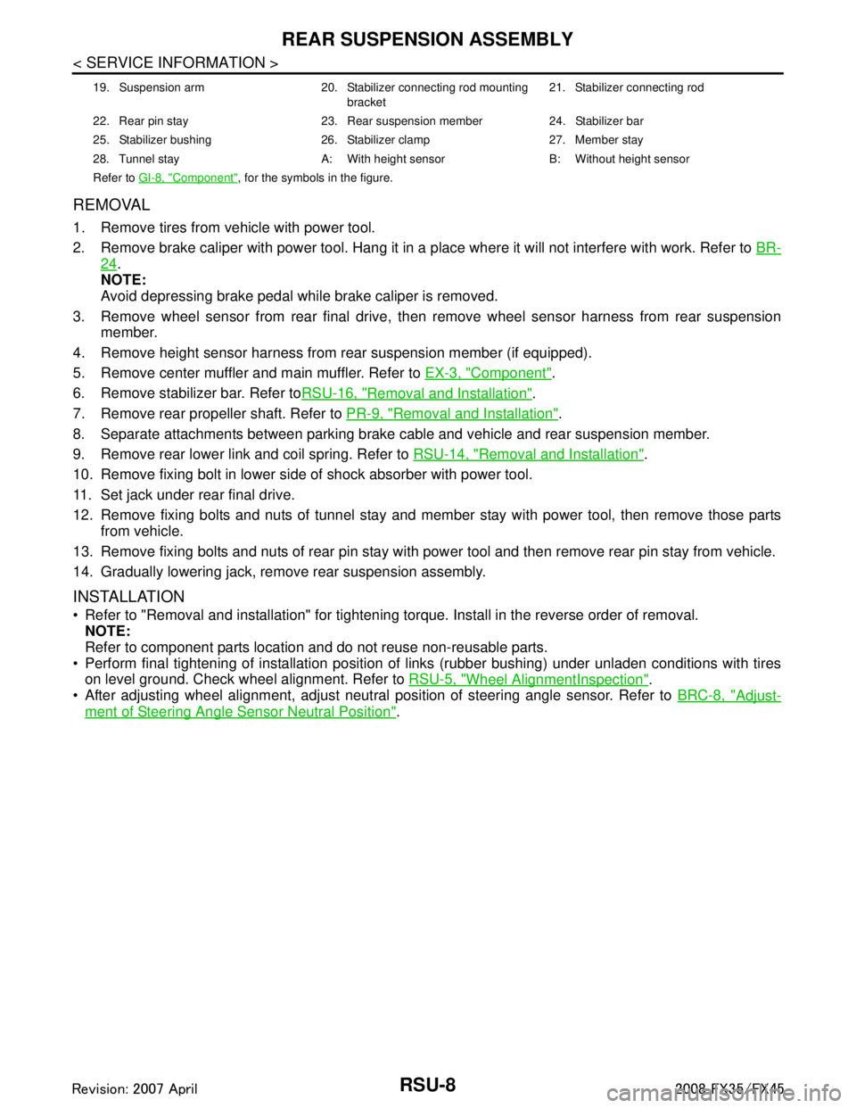
19. Suspension arm 20. Stabilizer connecting rod mounting
bracket21. Stabilizer connecting rod
22. Rear pin stay 23. Rear suspension member 24. Stabilizer bar
25. Stabilizer bushing 26. Stabilizer clamp 27. Member stay
28. Tunnel stay A: With height sensor B: Without height sensor
Refer to GI-8, "
Component", for the symbols in the figure.
3AA93ABC3ACD3AC03ACA3AC03AC63AC53A913A773A893A873A873A8E3A773A983AC73AC93AC03AC3
3A893A873A873A8F3A773A9D3AAF3A8A3A8C3A863A9D3AAF3A8B3A8C
Page 3598 of 3924
REAR SUSPENSION MEMBERRSU-17
< SERVICE INFORMATION >
C
DF
G H
I
J
K L
M A
B
RSU
N
O P
REAR SUSPENSION MEMBER
Removal and InstallationINFOID:0000000001327562
REMOVAL
1. Remove tires from vehicle with power tool.
2. Remove brake caliper with power tool. Hang it in a place where it will not interfere with work. Refer to BR-
24.
NOTE:
Avoid depressing brake pedal while brake caliper is removed.
3. Remove wheel sensor from rear final drive, t hen remove wheel sensor harness from rear suspension
member. Refer to BRC-52
.
4. Remove height sensor harness from rear suspension member (if equipped).
5. Remove center muffler and main muffler. Refer to EX-3
.
6. Remove stabilizer bar. Refer to RSU-16, "
Removal and Installation".
7. Remove rear drive shaft. Refer to RAX-10
.
8. Remove propeller shaft. Refer to PR-7
.
9. Remove rear final drive. Refer to RFD-16, "
Removal and Installation".
10. Separate attachments between parking brake cable and vehicle and rear suspension member. Refer to PB-4
.
11. Remove rear lower link and coil spring. Refer to RSU-14, "
Removal and Installation".
12. Remove fixing bolt in lower side of shock absorber with power tool.
13. Set jack under rear suspension member.
14. Remove fixing bolts and nuts of tunnel stay and member stay with power tool, then remove those parts from vehicle and rear suspension member.
15. Remove fixing bolts and nuts of rear pin stay with pow er tool and then remove rear pin stay from vehicle
and rear suspension member.
16. Slowly lowering jack, then remove rear suspension me mber, suspension arm, radius rod, front lower link
and axle from vehicle as a unit.
17. Remove fixing bolts and nuts with power tool, then re move suspension arm, front lower link, and radius
rod from rear suspension member.
INSPECTION AFTER REMOVAL
Check rear suspension member for deformation, cracks, and other damage and replace if necessary.
INSTALLATION
Refer to RSU-6, "Removal and Installation", for tightening torque. Install in the reverse order of removal.
NOTE:
Refer to component parts location and do not reuse non-reusable parts.
Perform final tightening of installation position of links (rubber bushing) under unladen conditions with tires
on level ground. Check wheel alignment. Refer to RSU-5, "
Wheel AlignmentInspection".
After adjusting wheel alignment, adjust neutral position of steering angle sensor. Refer to BRC-8, "
Adjust-
ment of Steering Angle Sensor Neutral Position".
3AA93ABC3ACD3AC03ACA3AC03AC63AC53A913A773A893A873A873A8E3A773A983AC73AC93AC03AC3
3A893A873A873A8F3A773A9D3AAF3A8A3A8C3A863A9D3AAF3A8B3A8C
Page 3599 of 3924

RSU-18
< SERVICE INFORMATION >
SERVICE DATA AND SPECIFICATIONS (SDS)
SERVICE DATA AND SPECIFICATIONS (SDS)
Wheel Alignment (Unladen*)INFOID:0000000001327563
*: Fuel, engine coolant and lubricant are oil full. Spare tire, jack, hand tools and mats are in designated positions.
Ball JointINFOID:0000000001327564
Wheelarch Height (Unladen*)INFOID:0000000001327565
*: Fuel, engine coolant and lubricant are oil full. Spare tire, jack, hand tools and mats are in designated positions.Camber
Degree minute (Decimal degree)
Minimum –1
°18 ′ (–1.30 °)
Nominal –0 °48 ′ (–0.80 °)
Maximum –0 °18 ′ (–0.30 °)
To t a l t o e - i n Distance
Minimum 2.4 mm (0.09 in)
Nominal 4.7 mm (0.19 in)
Maximum 7.0 mm (0.28 in)
Angle (left wheel or right wheel)
Degree minute (Decimal degree) Minimum 0
°05 ′ (0.08 °)
Nominal 0 °10 ′ (0.17 °)
Maximum 0 °15 ′ (0.25 °)
Axial end play 0 mm (0 in)
Swing torque 0.5 − 3.4 N·m (0.06 − 0.34 kg-m, 5 − 30 in-lb)
Measurement on spring balance (cotter pinhole position) 9.7 − 66.0 N (0.98 − 6.7 kg, 2.18 − 14.8 lb)
Rotating torque 0.5 − 3.4 N·m (0.06 − 0.34 kg-m, 5 − 30 in-lb)
Destination USA Canada
Engine VQ35DE VK45DE VQ35DE VK45DE
Axle 2WD AWD AWD
Tire size 265/60R18 265/50R20 265/60R18 265/50R20 265/60R18 265/50R20
Front (Hf) 835 mm
(32.87 in) 834 mm
(32.83 in) 834 mm
(32.83 in) 833 mm
(32.80 in) 832 mm
(32.76 in) 834 mm
(32.83 in) 833 mm
(32.80 in) 832 mm
(32.76 in)
Rear (Hr) 822 mm
(32.36 in) 821 mm
(32.32 in) 829 mm
(32.64 in) 827 mm
(32.56 in) 825 mm
(32.48 in) 827 mm
(32.56 in) 826 mm
(32.52 in) 823 mm
(32.40 in)
SFA818A
3AA93ABC3ACD3AC03ACA3AC03AC63AC53A913A773A893A873A873A8E3A773A983AC73AC93AC03AC3
3A893A873A873A8F3A773A9D3AAF3A8A3A8C3A863A9D3AAF3A8B3A8C
Page 3605 of 3924
SB-6
< SERVICE INFORMATION >
SEAT BELTS
6. Remove the outer side retractor and center seat retractor mounting anchor bolts.
7. Remove the seat belt assembly.
INSTALLATION OF REAR SEAT BELT RETRACTOR
Install in the reverse order of removal.
Seat Belt InspectionINFOID:0000000001327737
AFTER A COLLISION
WARNING:
Inspect all seat belt assemblies in cluding retractors and attaching hardware after any collision.
NISSAN recommends that all seat belt assemblies in use during a collision be replaced unless the col-
lision was minor and the belts show no damage and continue to operate properly. Failure to do so
could result in serious personal injury in an acci dent. Seat belt assemblies not in use during a colli-
sion should also be replaced if ei ther damage or improper operation is noted. Seat belt pre-tensioners
should be replaced even if the seat belts are not in use during a frontal collision in which the air bags
are deployed.
Replace any seat belt assembly (including anchor bolts) if:
The seat belt was in use at the time of a collision (except for minor collisions and the belts, retractors and
buckles show no damage and continue to operate properly).
The seat belt was damaged in an accident. (i.e. torn webbing, bent retractor or guide).
The seat belt attaching point was damaged in an acci dent. Inspect the seat belt attaching area for damage
or distortion and repair as necessary before installing a new seat belt assembly.
Anchor bolts are deformed or worn out.
The front seat belt pre-tensioner should be replaced even if the seat belts are not in use during the collision
in which the air bags are deployed.
PRELIMINARY CHECK
1. Check the seat belt warning lamp/chime for proper operation as follows:
a. Turn ignition switch ON. The seat belt warning lamp should illuminate. Also, the seat belt warning chime should sound for about six seconds.
b. Fasten driver's seat belt. The seat belt warni ng lamp should go out and the chime (if sounding) should
stop.
2. If the air bag warning lamp is blinking, perform self-diagnosis using CONSULT-II, and air bag warning lamp. Refer to SRS-23, "
SRS Operation Check".
3. Make sure that the seat belt retractor, seat belt anchor and buckle bolts are securely attached.
4. Check the shoulder seat belt guide and shoulder belt height adjuster for\
front seats. Ensure guide swivels freely and that webbing lays flat and does not bind in guide. Ensure height adjuster operates properly and
holds securely.
5. Check retractor operation:
a. Fully extend the seat belt webbing and c heck for twists, tears or other damage.
b. Allow the seat belt to retract. Ensure that webbing returns smoothly and completely into the retractor. If
the seat belt does not return smoothly, wipe the insi de of the loops with a clean paper cloth, because dirt
built up in the loops of the upper anchors can cause the seat belts to retract slowly.
c. Fasten the seat belt. Check the seat belt returns sm oothly and completely to the retractor. If the webbing
does not return smoothly, the cause may be an accumulation of dust or dirt. Use the “SEAT BELT TAPE
SET” and perform the following steps.
Inspect the front seat belt through-anchor:
1. Pull the seat belt out to a length of 500 mm (19.69 in) or more.
2. Use a clip or other device to the fix the seat belt at the center pillar webbing opening.
3. Pass a thin wire through the through-anchor webbing opening. Hold both ends of the wire and pull taut while moving it up and down several times along the webbing opening surface to remove dirt.
4. Any dirt that cannot be removed with the wir e can be removed by cleaning the opening with a clean
cloth.
5. Apply tape at the point where the webbi ng contacts the through-anchor webbing opening.
NOTE:
Apply the tape so that there is no looseness or wrinkling.
6. Remove the clip fixing the seat belt and ensure that the webbing returns smoothly.
3AA93ABC3ACD3AC03ACA3AC03AC63AC53A913A773A893A873A873A8E3A773A983AC73AC93AC03AC3
3A893A873A873A8F3A773A9D3AAF3A8A3A8C3A863A9D3AAF3A8B3A8C
Page 3639 of 3924

SC-30
< SERVICE INFORMATION >
SERVICE DATA AND SPECIFICATIONS (SDS)
SERVICE DATA AND SPECIFICATIONS (SDS)
BatteryINFOID:0000000001328260
StarterINFOID:0000000001328261
AlternatorINFOID:0000000001328262
Typ e11 0 D 2 6 L
Capacity V - AH 12 - 75
Cold cranking current (F or reference value) A 720
Applied model VK45DE VQ3 5DE (2WD) VQ35DE (AWD)
Ty p e M002T85075 S114-880A S114-881A
MITSUBISHI make HITACHI make Reduction gear type
System voltage V 12
No-load Te r m i n a l v o l t a g e V 11
Current A Less than 145 Less than 90
Revolution rpm More than 3,300 More than 2,880
Minimum diameter of commutator mm (in) 31.4 (1.236) 28.0 (1.102)
Minimum length of brush mm (in) 11.0 (0.433) 10.5 (0.413)
Brush spring tension N (kg, lb) 26.7 - 36.1
(2.72 - 3.68,
6.80 - 8.12) 16.2 (1.65, 3.6)
Clearance between bearing metal and armature shaft mm (in) Less than 0.2 (0.008)
Clearance between pinion front edge and pinion stopper mm (in) 0.5 - 2.0
(0.020 - 0.079) —
Movement in height of pinion assembly mm (in) — 0.3 - 2.5 (0.012 - 0.098)
Applied model VK45DE VQ35DE
Ty p e LR1110 - 716B A3TG0191
HITACHI make MITSUBISHI make
Nominal rating V - A 12 - 110
Ground polarity Negative
Minimum revolution under no-load (When 13.5 V is applied) rpm Less than 1,100 Less than 1,000
Hot output current (When 13.5 V is applied) A/rpm More than 70/1,800
More than 91/2,500
More than 110/5,000 More than 37/1,300
More than 92/2,500
More than 103/5,000
Regulated output voltage V 14.1 - 14.7
Minimum length of brush mm (in) More than 6.00 (0.236) More than 5.00 (0.197)
Brush spring pressure N (g, oz) 1.00 - 3.43
(102 - 350, 3.60 - 12.34) 4.8 - 6.0
(490 - 612, 17.28 - 21.60)
Slip ring minimum outer diameter mm (in) More than 26.0 (1.024) More than 22.1 (0.870)
Rotor (Field coil) resistance Ω2.31 1.7 - 2.1
3AA93ABC3ACD3AC03ACA3AC03AC63AC53A913A773A893A873A873A8E3A773A983AC73AC93AC03AC3
3A893A873A873A8F3A773A9D3AAF3A8A3A8C3A863A9D3AAF3A8B3A8C
Page 3918 of 3924

REAR WIPER AND WASHER SYSTEMWW-43
< SERVICE INFORMATION >
C
DE
F
G H
I
J
L
M A
B
WW
N
O P
Washer Nozzle AdjustmentINFOID:0000000001328592
Adjust spray positions as shown in the figure.
Unit: mm (in)
Insert a needle or suitable tool into the nozzle hole and move it to adjust the spray position.
Washer Tube LayoutINFOID:0000000001328593
Removal and Installation of Washer NozzleINFOID:0000000001328594
REMOVAL
Spray position h (height) (width)φ
S
A, B 2.5 (0.098) 80 (3.15) 30 (1.18)
SKIA5088E
Adjustable range : ± 15 ° (In any direction)
SKIA5087E
PKIC9709E
3AA93ABC3ACD3AC03ACA3AC03AC63AC53A913A773A893A873A873A8E3A773A983AC73AC93AC03AC3
3A893A873A873A8F3A773A9D3AAF3A8A3A8C3A863A9D3AAF3A8B3A8C