height INFINITI FX35 2008 User Guide
[x] Cancel search | Manufacturer: INFINITI, Model Year: 2008, Model line: FX35, Model: INFINITI FX35 2008Pages: 3924, PDF Size: 81.37 MB
Page 989 of 3924

BRAKE PEDALBR-5
< SERVICE INFORMATION >
C
DE
G H
I
J
K L
M A
B
BR
N
O P
BRAKE PEDAL
Inspection and AdjustmentINFOID:0000000001327607
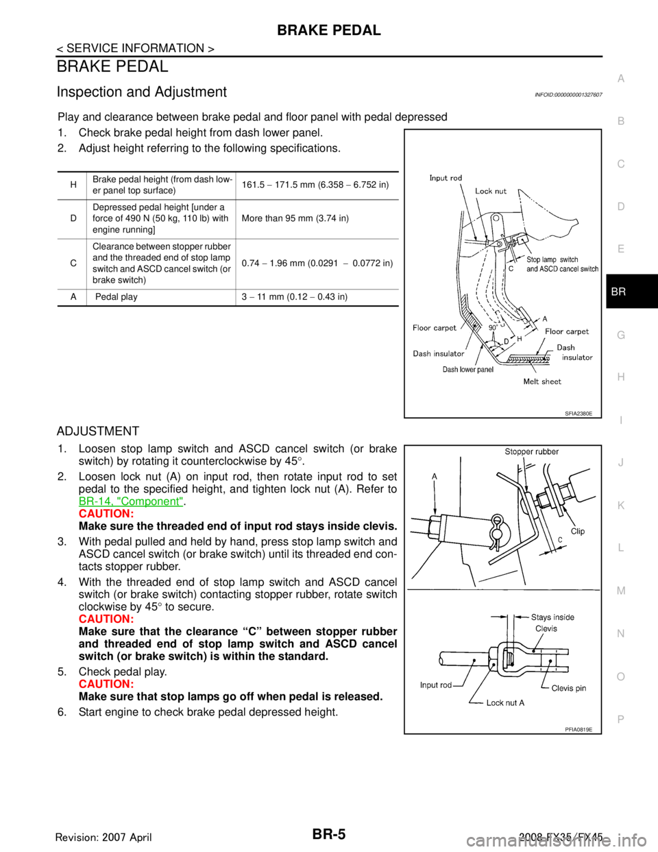
Play and clearance between brake pedal and floor panel with pedal depressed
1. Check brake pedal height from dash lower panel.
2. Adjust height referring to the following specifications.
ADJUSTMENT
1. Loosen stop lamp switch and ASCD cancel switch (or brake switch) by rotating it counterclockwise by 45 °.
2. Loosen lock nut (A) on input rod, then rotate input rod to set pedal to the specified height, and tighten lock nut (A). Refer to
BR-14, "
Component".
CAUTION:
Make sure the threaded end of input rod stays inside clevis.
3. With pedal pulled and held by hand, press stop lamp switch and ASCD cancel switch (or brake switch) until its threaded end con-
tacts stopper rubber.
4. With the threaded end of stop lamp switch and ASCD cancel switch (or brake switch) contacting stopper rubber, rotate switch
clockwise by 45 ° to secure.
CAUTION:
Make sure that the clearance “C” between stopper rubber
and threaded end of stop lamp switch and ASCD cancel
switch (or brake switch) is within the standard.
5. Check pedal play. CAUTION:
Make sure that stop lamps go off when pedal is released.
6. Start engine to check brake pedal depressed height.
H Brake pedal height (from dash low-
er panel top surface) 161.5
− 171.5 mm (6.358 − 6.752 in)
D Depressed pedal height [under a
force of 490 N (50 kg, 110 lb) with
engine running] More than 95 mm (3.74 in)
C Clearance between stopper rubber
and the threaded end of stop lamp
switch and ASCD cancel switch (or
brake switch) 0.74
− 1.96 mm (0.0291 −0.0772 in)
A Pedal play 3 − 11 mm (0.12 − 0.43 in)
SFIA2380E
PFIA0819E
3AA93ABC3ACD3AC03ACA3AC03AC63AC53A913A773A893A873A873A8E3A773A983AC73AC93AC03AC3
3A893A873A873A8F3A773A9D3AAF3A8A3A8C3A863A9D3AAF3A8B3A8C
Page 991 of 3924

BRAKE PEDALBR-7
< SERVICE INFORMATION >
C
DE
G H
I
J
K L
M A
B
BR
N
O P
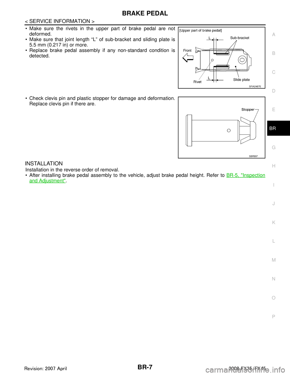
Make sure the rivets in the upper part of brake pedal are not deformed.
Make sure that joint length “L” of sub-bracket and sliding plate is
5.5 mm (0.217 in) or more.
Replace brake pedal assembly if any non-standard condition is detected.
Check clevis pin and plastic stopper for damage and deformation. Replace clevis pin if there are.
INSTALLATION
Installation in the reverse order of removal.
After installing brake pedal assembly to the vehicle, adjust brake pedal height. Refer to BR-5, "
Inspection
and Adjustment".
SFIA2487E
SBR997
3AA93ABC3ACD3AC03ACA3AC03AC63AC53A913A773A893A873A873A8E3A773A983AC73AC93AC03AC3
3A893A873A873A8F3A773A9D3AAF3A8A3A8C3A863A9D3AAF3A8B3A8C
Page 999 of 3924

BRAKE BOOSTERBR-15
< SERVICE INFORMATION >
C
DE
G H
I
J
K L
M A
B
BR
N
O P
CAUTION:
Be careful not to splash brake fluid on painted areas; it may cause paint damage. If brake fluid is
splashed on painted surfaces of body, immediately wipe it off and them wash it away with water
immediately.
Be careful not to deform or bend brake tube while removing and installing brake booster.
Replace clevis pin if it is damaged.
Be careful not to damage brake booster stud bolt thr eads. If brake booster is tilted or inclined during
installation, dash panel may damage the threads.
Install the check valve in the correct direction.
1. Remove vacuum hose from brake booster. Refer to BR-16
.
2. Remove brake master cylinder. Refer to BR-12, "
Removal and Installation".
3. Disconnect harness connector from brake booster assembly. (ICC model)
4. Remove snap pin and clevis pin from inside the vehicle. Refer to BR-6, "
Component".
5. Remove nuts from brake booster and brake pedal bracket.
6. Remove brake booster assembly from engine room.
INSPECTION AFTER REMOVAL
Output Rod Length Inspection
1. Using a handy vacuum pump, apply a vacuum of –66.7 kPa (– 500 mmHg, –19.69 inHg) to brake booster.
2. Check output rod length.
INSTALLATION
1. Loosen lock nut to adjust input r od length so that the length “B”
(shown in the figure) satisfies the specified value.
2. After adjusting “B”, temporarily tighten lock nut to install brake booster assembly to the vehicle. At this time, make sure to
install a gasket between brake booster assembly and the engine
room.
3. Connect brake pedal with clevis of input rod.
4. Install brake pedal bracket mounting nuts and bolt and tighten them to the specified torque. BR-6, "
Component".
5. Install brake tube from brake master cylinder to ABS actuator. Refer to BR-10, "
Hydraulic Circuit".
6. Install master cylinder to booster assembly. Refer to BR-12, "
Removal and Installation".
7. Adjust the height and play of brake pedal. BR-5, "
Inspection and Adjustment".
8. Tighten lock nut of input rod to the specified torque. Refer to BR-14, "
Component".
9. Bleed air. Refer to BR-8, "
Bleeding Brake System".
Standard dimension when
applying a vacuum of
− 66.7 kPa ( −500 mmHg, −19.69 inHg):
15.6 − 15.9 mm (0.614 − 0.626 in)
SFIA2146E
Length “B” : 126.5 mm (4.98 in)
SGIA0060E
3AA93ABC3ACD3AC03ACA3AC03AC63AC53A913A773A893A873A873A8E3A773A983AC73AC93AC03AC3
3A893A873A873A8F3A773A9D3AAF3A8A3A8C3A863A9D3AAF3A8B3A8C
Page 1014 of 3924

BR-30
< SERVICE INFORMATION >
SERVICE DATA AND SPECIFICATIONS (SDS)
SERVICE DATA AND SPECIFICATIONS (SDS)
General SpecificationINFOID:0000000001327639
Unit: mm (in)
Brake PedalINFOID:0000000001327640
Brake BoosterINFOID:0000000001327641
Vacuum type
Check ValveINFOID:0000000001327642
Front Disc BrakeINFOID:0000000001327643
Rear Disc BrakeINFOID:0000000001327644
Front brakeRotor outer diameter
× thickness 320 × 34 (12.598 × 1.339)
Pad length × width × thickness 130.0 × 50.0 × 11.0 (5.118 × 1.969 × 0.433)
Cylinder bore diameter 45.0 (1.772) × 2
Rear brake Rotor outer diameter
× thickness 308 × 16 (12.13 × 0.63)
Pad length × width × thickness 83.0 × 33.0 × 8.5 (3.268 × 1.299 × 0.335)
Cylinder bore diameter 42.86 (1.6874)
Master cylinder Cylinder bore diameter 25.4 (1.00)
Control valve Valve model Electric brake force distribution
Brake booster Diaphragm diameter Primary 228.5 (9.0)
Secondary 203.0 (8.0)
Recommended brake fluid DOT 3
Brake pedal height (from dash lower panel top surface) 161.5 − 171.5 mm (6.358 − 6.752 in)
Depressed pedal height
[under a force of 490 N (50 kg, 110 lb) with engine running] More than 95 mm (3.74 in)
Clearance between stopper rubber and the threaded end of stop lamp
switch and ASCD cancel switch (or brake switch) 0.74
− 1.96 mm (0.0291 − 0.0772 in)
Pedal play 3 − 11 mm (0.12 − 0.43 in)
Output rod length 15.6 − 15.9 mm (0.614 − 0.626 in)
Input rod length 126.5 mm (4.98 in)
Vacuum leakage
[at a vacuum of –66.7 kPa (–500 mmHg, –19.69 inHg)]Within vacuum of 1.3 kPa (10 mmHg, 0.39 inHg) for 15
seconds
Brake padStandard thickness 11.0 mm (0.433 in)
Repair limit thickness 2.0 mm (0.079 in)
Disc rotor Standard thickness 34.0 mm (1.339 in)
Wear limit 32.0 mm (1.260 in)
Maximum uneven wear (measured at 8 positions) 0.015mm (0.0006 in) or less
Runout limit (with the disc rotor attached to the vehicle) 0.04 mm (0.0016 in) or less
Brake pad
Standard thickness 8.5 mm (0.335 in)
Repair limit thickness 2.0 mm (0.079 in)
3AA93ABC3ACD3AC03ACA3AC03AC63AC53A913A773A893A873A873A8E3A773A983AC73AC93AC03AC3
3A893A873A873A8F3A773A9D3AAF3A8A3A8C3A863A9D3AAF3A8B3A8C
Page 1089 of 3924
![INFINITI FX35 2008 User Guide
CO-18
< SERVICE INFORMATION >[VQ35DE]
RADIATOR (ALUMINUM TYPE)
2. Install new sealing rubber while pushing it with fingers.
CAUTION:
Be careful not to twist sealing rubber.
3. Caulk tank in numerical INFINITI FX35 2008 User Guide
CO-18
< SERVICE INFORMATION >[VQ35DE]
RADIATOR (ALUMINUM TYPE)
2. Install new sealing rubber while pushing it with fingers.
CAUTION:
Be careful not to twist sealing rubber.
3. Caulk tank in numerical](/img/42/57017/w960_57017-1088.png)
CO-18
< SERVICE INFORMATION >[VQ35DE]
RADIATOR (ALUMINUM TYPE)
2. Install new sealing rubber while pushing it with fingers.
CAUTION:
Be careful not to twist sealing rubber.
3. Caulk tank in numerical order as shown in the figure with the radiator plate pliers A (SST).
Use pliers in the locations where the radiator plate pliers A
[SST: KV99103510 ( — )] cannot be used.
4. Make sure that the rim is completely crimped down.
SLC917A
SLC904-A
PBIC2076E
SLC897
Standard height “H” : 8.0 - 8.4 mm (0.315 - 0.331 in)
SLC554A
3AA93ABC3ACD3AC03ACA3AC03AC63AC53A913A773A893A873A873A8E3A773A983AC73AC93AC03AC3
3A893A873A873A8F3A773A9D3AAF3A8A3A8C3A863A9D3AAF3A8B3A8C
Page 1117 of 3924
![INFINITI FX35 2008 User Guide
CO-46
< SERVICE INFORMATION >[VK45DE]
RADIATOR (ALUMINUM TYPE)
2. Install new sealing rubber while pushing it with fingers.
CAUTION:
Be careful not to twist sealing rubber.
3. Caulk tank in numerical INFINITI FX35 2008 User Guide
CO-46
< SERVICE INFORMATION >[VK45DE]
RADIATOR (ALUMINUM TYPE)
2. Install new sealing rubber while pushing it with fingers.
CAUTION:
Be careful not to twist sealing rubber.
3. Caulk tank in numerical](/img/42/57017/w960_57017-1116.png)
CO-46
< SERVICE INFORMATION >[VK45DE]
RADIATOR (ALUMINUM TYPE)
2. Install new sealing rubber while pushing it with fingers.
CAUTION:
Be careful not to twist sealing rubber.
3. Caulk tank in numerical order as shown in the figure with radia- tor plate pliers A (SST).
Use pliers in the locations where radiator plate pliers A [SST:
KV99103510 ( — )] cannot be used.
4. Make sure that the rim is completely crimped down.
SLC917A
SLC904-A
PBIC2076E
SLC897
Standard height “H” : 8.0 - 8.4 mm (0.315 - 0.331 in)
SLC554A
3AA93ABC3ACD3AC03ACA3AC03AC63AC53A913A773A893A873A873A8E3A773A983AC73AC93AC03AC3
3A893A873A873A8F3A773A9D3AAF3A8A3A8C3A863A9D3AAF3A8B3A8C
Page 1200 of 3924

DI-74
< SERVICE INFORMATION >
LANE DEPARTURE WARNING SYSTEM
The target may not be detected when there is the same pattern of black and white as the target when
the pattern is within 1 m (3.28 ft) from either si de and upward/downward position from the target. (It
is desirable that the vehicle is positioned on the opposite side of a single-color wall.)
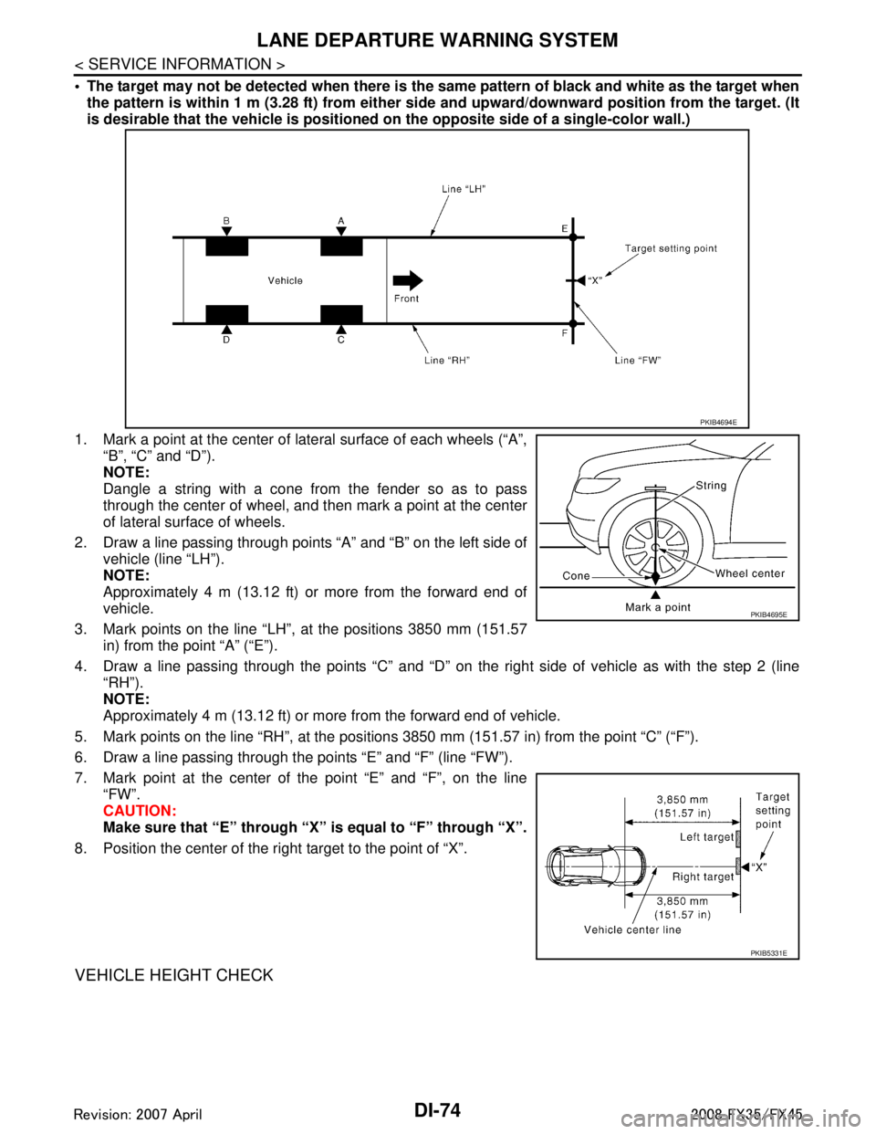
1. Mark a point at the center of lateral surface of each wheels (“A”,
“B”, “C” and “D”).
NOTE:
Dangle a string with a cone from the fender so as to pass
through the center of wheel, and t hen mark a point at the center
of lateral surface of wheels.
2. Draw a line passing through points “A” and “B” on the left side of vehicle (line “LH”).
NOTE:
Approximately 4 m (13.12 ft) or more from the forward end of
vehicle.
3. Mark points on the line “LH”, at the positions 3850 mm (151.57 in) from the point “A” (“E”).
4. Draw a line passing through the points “C” and “D” on t he right side of vehicle as with the step 2 (line
“RH”).
NOTE:
Approximately 4 m (13.12 ft) or more from the forward end of vehicle.
5. Mark points on the line “RH”, at the positions 3850 mm (151.57 in) from the point “C” (“F”).
6. Draw a line passing through the points “E” and “F” (line “FW”).
7. Mark point at the center of the point “E” and “F”, on the line
“FW”.
CAUTION:
Make sure that “E” through “X” is equal to “F” through “X”.
8. Position the center of the right target to the point of “X”.
VEHICLE HEIGHT CHECK
PKIB4694E
PKIB4695E
PKIB5331E
3AA93ABC3ACD3AC03ACA3AC03AC63AC53A913A773A893A873A873A8E3A773A983AC73AC93AC03AC3
3A893A873A873A8F3A773A9D3AAF3A8A3A8C3A863A9D3AAF3A8B3A8C
Page 1201 of 3924

LANE DEPARTURE WARNING SYSTEMDI-75
< SERVICE INFORMATION >
C
DE
F
G H
I
J
L
M A
B
DI
N
O P
Measure the wheel arch height. And calculate “Dh”.
NOTE:
“Dh” may be calculated as a minus value.
AIMING ADJUSTMENT
Operation Procedure
CAUTION:
Perform the adjustment under unloaded vehicle condition.
LDW indicator is turned off after the remo val/installation, and blinks after replacement.
NOTE:
When the DTC (C1B01 CAM AIMING INCMP) is disp layed on CONSULT-III screen, perform the aiming
adjustment after erasing the DTC.
1. Select “Work Support” on LDW with CONSULT-III.
2. Select “AUTO AIM”.
3. Confirm following.
a. The target should be accurately placed.
b. The vehicle should be stopped.
4. Select “Start” to perform aiming.
CAUTION:
Never Select “Start” when the target is not placed.
5. Input “Dh”, and then select “Start”. NOTE:
Check the value “Dh”. Refer to "VEHICLE HEIGHT CHECK".
CAUTION:
Never change “Ht” and “Dt”.
6. Check it display item.
a. “Normally Completed” is displayed, then selecting “Completion”.
b. Perform the following services when displa yed “SUSPENSION” or “ABNORMALLY COMPLETED”.
NOTE:
Replace camera unit if “SUSPENSION” is repeatedly indicated though the above tw o service is performed.
7. Check if “Normally Completed” is displayed and close the aiming adjustment procedure by selecting
“End”.
Check After The Adjustment
1. Perform self-diagnosis of LDW camera unit. Refer to DI-81, "CONSULT-III Function (LDW)".
2. Test the LDW system operation by running test. Refer to DI-71, "
Action Test".
Dh [mm] = (Hfl + Hfr)
÷ 2 − 840
where, Hfl: Front left wheel arch height [mm]
Hfr: Front right wheel arch height [mm]
SKIB3164E
Displays item Service procedure
SUSPENSION 00H Routine not activated
Position the target appropriately again. Perform the aiming again.
Refer to "Camera Aiming Adjustment".
10H Writing error
ABNORMALLY COMPLETED —
3AA93ABC3ACD3AC03ACA3AC03AC63AC53A913A773A893A873A873A8E3A773A983AC73AC93AC03AC3
3A893A873A873A8F3A773A9D3AAF3A8A3A8C3A863A9D3AAF3A8B3A8C
Page 1210 of 3924

DI-84
< SERVICE INFORMATION >
LANE DEPARTURE WARNING SYSTEM
Preliminary Check
INFOID:0000000001328502
1.CHECK CAMERA LENS AND WINDSHIELD
Are camera lens and windshield contaminated with foreign materials?
YES >> Clean camera lens and windshield.
NO >> GO TO 2.
2.CHECK CAMERA UNIT IN STALLATION CONDITION
Check camera unit installation condition (installat ion position, properly tightened, a bent bracket).
OK or NG
OK >> GO TO 3.
NG >> Install camera unit properly, and adjust camera aiming. Refer to DI-71, "
Camera Aiming Adjust-
ment".
3.CHECK VEHICLE HEIGHT
Check vehicle height. Refer to GI-47, "
Dimensions".
Is vehicle height appropriate?
OK >> GO TO 4.
NG >> Repair vehicle to appropriate height.
4.CHECK LDW CAMERA UNIT (CONSULT-III)
Perform self-diagnosis of LDW camera unit. Refer to DI-81, "
CONSULT-III Function (LDW)".
Self
-diagnosis results
No malfunction detected >> GO TO 5.
Malfunction detected >> Check applicable parts, and repair or replace corresponding parts.
5.CHECK COMBINATION METER
Check combination meter function.
Do speedometer and turn signal indicator normal function?
YES >> INSPECTION END
NO >> Check combination meter. Refer to DI-15, "
Trouble Diagnosis".
Power Supply and Ground Circuit InspectionINFOID:0000000001328503
1.CHECK FUSE
Check for blown LDW camera unit fuse.
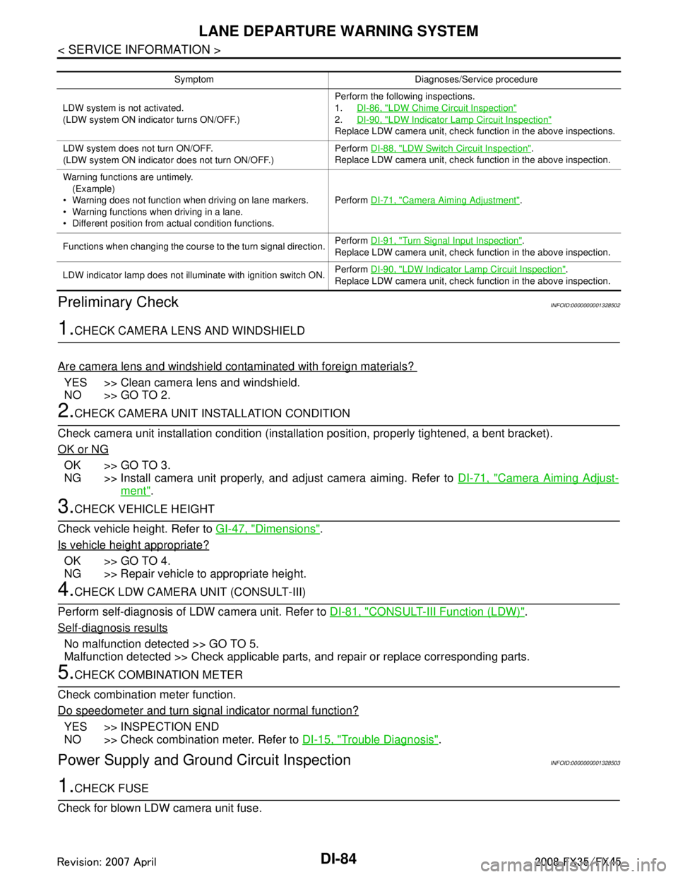
Symptom Diagnoses/Service procedure
LDW system is not activated.
(LDW system ON indicator turns ON/OFF.) Perform the following inspections.
1.
DI-86, "
LDW Chime Circuit Inspection"
2.DI-90, "LDW Indicator Lamp Circuit Inspection"
Replace LDW camera unit, check function in the above inspections.
LDW system does not turn ON/OFF.
(LDW system ON indicator does not turn ON/OFF.) Perform
DI-88, "
LDW Switch Circuit Inspection".
Replace LDW camera unit, check function in the above inspection.
Warning functions are untimely. (Example)
Warning does not function when driving on lane markers.
Warning functions when driving in a lane.
Different position from actual condition functions. Perform
DI-71, "
Camera Aiming Adjustment".
Functions when changing the course to the turn signal direction. Perform
DI-91, "
Turn Signal Input Inspection".
Replace LDW camera unit, check function in the above inspection.
LDW indicator lamp does not illuminate with ignition switch ON. Perform
DI-90, "
LDW Indicator Lamp Circuit Inspection".
Replace LDW camera unit, check function in the above inspection.
3AA93ABC3ACD3AC03ACA3AC03AC63AC53A913A773A893A873A873A8E3A773A983AC73AC93AC03AC3
3A893A873A873A8F3A773A9D3AAF3A8A3A8C3A863A9D3AAF3A8B3A8C
Page 1399 of 3924
![INFINITI FX35 2008 User Guide
DTC P0031, P0032, P0051, P0052 A/F SENSOR 1 HEATER
EC-159
< SERVICE INFORMATION > [VQ35DE]
C
D
E
F
G H
I
J
K L
M A
EC
NP
O
Check resistance between terminals 3 and 4.
Check continuity between termina INFINITI FX35 2008 User Guide
DTC P0031, P0032, P0051, P0052 A/F SENSOR 1 HEATER
EC-159
< SERVICE INFORMATION > [VQ35DE]
C
D
E
F
G H
I
J
K L
M A
EC
NP
O
Check resistance between terminals 3 and 4.
Check continuity between termina](/img/42/57017/w960_57017-1398.png)
DTC P0031, P0032, P0051, P0052 A/F SENSOR 1 HEATER
EC-159
< SERVICE INFORMATION > [VQ35DE]
C
D
E
F
G H
I
J
K L
M A
EC
NP
O
Check resistance between terminals 3 and 4.
Check continuity between terminals
3 and 1, 2, 5, 6, terminals 4 and
1, 2, 5, 6.
If NG, replace the air fuel ratio (A/F) sensor 1.
CAUTION:
Discard any air fuel ratio (A/F) sensor which has been dropped from a height of more than 0.5 m (19.7 in) onto a hard
surface such as a concrete floor; use a new one.
Before installing new air fuel ratio (A/F) sensor, clean exhaust
system threads using Heated O xygen Sensor Thread Cleaner
tool J-43897-18 or J-43897-12 and approved anti-seize lubri-
cant.
Removal and InstallationINFOID:0000000001325972
AIR FUEL RATIO (A/F) SENSOR 1
Refer to EM-26.
Resistance: 2.3 - 4.3
Ω [at 25 °C (77 °F)]
Continuity should not exist.
PBIB1684E
3AA93ABC3ACD3AC03ACA3AC03AC63AC53A913A773A893A873A873A8E3A773A983AC73AC93AC03AC3
3A893A873A873A8F3A773A9D3AAF3A8A3A8C3A863A9D3AAF3A8B3A8C