key INFINITI FX35 2008 Service Manual
[x] Cancel search | Manufacturer: INFINITI, Model Year: 2008, Model line: FX35, Model: INFINITI FX35 2008Pages: 3924, PDF Size: 81.37 MB
Page 2914 of 3924

GW-1
BODY
C
DE
F
G H
J
K L
M
SECTION GW
A
B
GW
N
O P
CONTENTS
GLASSES, WINDOW SYSTEM & MIRRORS
SERVICE INFORMATION .. ..........................3
PRECAUTIONS .............................................. .....3
Precaution for Supplemental Restraint System
(SRS) "AIR BAG" and "SEAT BELT PRE-TEN-
SIONER" ............................................................. ......
3
Precaution for Procedure without Cowl Top Cover ......3
Handling for Adhesive and Primer ............................3
PREPARATION ...................................................4
Special Service Tool ........................................... ......4
Commercial Service Tool ..........................................4
SQUEAK AND RATTLE TROUBLE DIAG-
NOSES ................................................................
5
Work Flow ........................................................... ......5
Generic Squeak and Rattle Troubleshooting ............7
Diagnostic Worksheet ...............................................9
WINDSHIELD GLASS ........................................11
Removal and Installation ..................................... ....11
BACK DOOR WINDOW GLASS ........................13
Removal and Installation ..................................... ....13
POWER WINDOW SYSTEM ..............................15
Component Parts and Harness Connector Loca-
tion ...................................................................... ....
15
System Description .................................................15
CAN Communication System Description ...............18
CAN Communication Unit .......................................19
Schematic ...............................................................19
Wiring Diagram - WINDOW - ..................................20
Terminal and Reference Value for BCM .................23
Terminal and Reference Value for Power Window
Main Switch .............................................................
24
Terminal and Reference Value for Front Power
Window Switch (Passenger Side) ...........................
25
CONSULT-III Function ............................................26
Work Flow ...............................................................27
Trouble Diagnosis Symptom Chart .........................27
Check BCM Power Supply and Ground Circuit .......28
Check Power Window Main Switch Power Supply
Circuit .................................................................. ....
28
Check Front Power Window Switch (Passenger
Side) Power Supply and Ground Circuit ..................
30
Check Front Power Window Motor (Driver Side)
Circuit ......................................................................
30
Check Front Power Window Motor (Passenger
Side) Circuit .............................................................
31
Check rear Power Window Motor (LH) Circuit .........32
Check Rear Power Window Motor (RH) Circuit .......34
Check Limit Switch Circuit (Driver Side) .............. ....36
Check Limit Switch Circuit (Passenger Side) ..........37
Check Encoder Circuit (Driver Side) ........................39
Check Encoder Circuit (Passenger Side) ................40
Check Door Switch ..................................................42
Check Front Door Key Cylinder Switch ...................43
Check Power Window Serial Link (Passenger
Side) ........................................................................
45
Check Power Window Lock Switch .........................46
SIDE WINDOW GLASS ....................................48
Removal and Installation .........................................48
FRONT DOOR GLASS AND REGULATOR .....50
Removal and Installation .........................................50
Disassembly and assembly .....................................52
Inspection after Installation ......................................52
REAR DOOR GLASS AND REGULATOR .......54
Removal and Installation .........................................54
Disassembly and assembly .....................................56
Fitting Inspection .....................................................56
INSIDE MIRROR ...............................................57
Wiring Diagram - I/MIRR - .......................................57
Removal and Installation .........................................58
REAR WINDOW DEFOGGER ..........................60
Component Parts and Harness Connector Loca-
tion ...........................................................................
60
System Description ..................................................60
CAN Communication System Description ...............61
3AA93ABC3ACD3AC03ACA3AC03AC63AC53A913A773A893A873A873A8E3A773A983AC73AC93AC03AC3
3A893A873A873A8F3A773A9D3AAF3A8A3A8C3A863A9D3AAF3A8B3A8C
Page 2928 of 3924
POWER WINDOW SYSTEMGW-15
< SERVICE INFORMATION >
C
DE
F
G H
J
K L
M A
B
GW
N
O P
POWER WINDOW SYSTEM
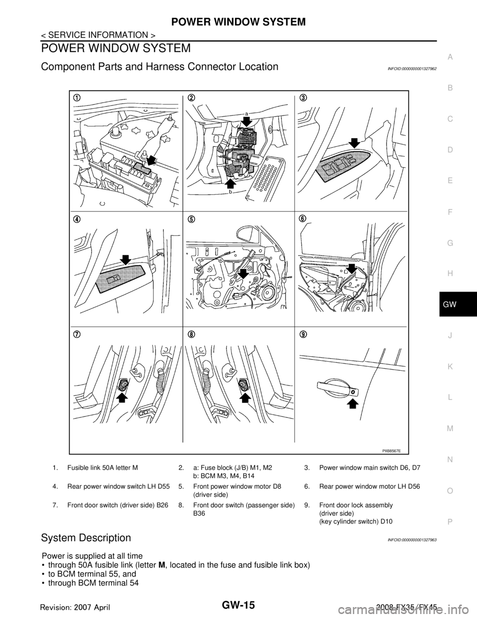
Component Parts and Har ness Connector LocationINFOID:0000000001327962
System DescriptionINFOID:0000000001327963
Power is supplied at all time
through 50A fusible link (letter M, located in the fuse and fusible link box)
to BCM terminal 55, and
through BCM terminal 54
1. Fusible link 50A letter M 2. a: Fuse block (J/B) M1, M2
b: BCM M3, M4, B143. Power window main switch D6, D7
4. Rear power window switch LH D55 5. Front power window motor D8 (driver side)6. Rear power window motor LH D56
7. Front door switch (driver side) B26 8. Front door switch (passenger side) B369. Front door lock assembly
(driver side)
(key cylinder switch) D10
PIIB8567E
3AA93ABC3ACD3AC03ACA3AC03AC63AC53A913A773A893A873A873A8E3A773A983AC73AC93AC03AC3
3A893A873A873A8F3A773A9D3AAF3A8A3A8C3A863A9D3AAF3A8B3A8C
Page 2931 of 3924
GW-18
< SERVICE INFORMATION >
POWER WINDOW SYSTEM
The one is applied only for front doors and the other is for all doors.
POWER WINDOW SERIAL LINK
Power window main switch, front power window switch (passenger side), and BCM transmit and receive the
signal by power window serial link.
The under mentioned signal is transmitted from BCM to power window main switch and front power window
switch (passenger side)
Keyless power window down signal.
The under mentioned signal is transmitted from power window main switch to front power window switch (pas-
senger side)
Front passenger side door window operation signal.
Power window control by key cylinder switch signal.
Power window lock signal.
Retained power operation signal.
POWER WINDOW LOCK
The power window lock is designed to lock operation of all windows except for driver side door window.
When the lock position, ground of the rear power window switches in the power window main switch is discon-
nected. The power window lock signal is transmitted to front power window switch (passenger side) by power
window serial link. This prevents t he power window motors from operating.
RETAINED POWER OPERATION
When the ignition switch is turned to the OFF position from ON or START position.
Power is supplied for 45 seconds
through BCM terminal 53
to power window main switch terminal 10
to rear power window switch (LH and RH) terminals 1.
When power and ground are supplied, the BCM conti nues to be energized, and the power window can be
operated.
The retained power operation is canceled when the driver or passenger side door is opened.
RAP signal period can be changed by CONSULT-III. Refer to GW-26, "
CONSULT-III Function".
ANTI-PINCH SYSTEM
Power window main switch and front power window switch (passenger side) monitors the power window motor
operation and the power window position (full closed or other) for driver side and passenger side power win-
dow by the signals from encoder and limit switch in front power window motor (driver side and passenger
side).
When power window main switch detects inte rruption during the following close operation,
automatic close operation when igniti on switch is in the “ON” position
automatic close operation during retained power operation
manual close operation during retained power operation
power window main switch or front power window swit ch (passenger side) controls each power window motor
for open and the power window will be lowered about 150 mm (5.91 in).
POWER WINDOW CONTROL BY THE KEY CYLINDER SWITCH
When ignition key switch is OFF, front power window can be opened or closed by turning the key cylinder
switch UNLOCK / LOCK position more than 1.5 second over condition.
Power window can be opened as the door key cylinder is kept fully turning to the UNLOCK position.
Power window can be closed as the door key cylinder is kept fully turning to the LOCK position.
The power window DOWN stops when the following operations are carried out.
While performing open / close the window, power window is stopped at the position as the door key cylinder is placed on NEUTRAL.
When the ignition switch is turned ON while the power window DOWN is operated.
CAN Communication System DescriptionINFOID:0000000001327964
CAN (Controller Area Network) is a serial communication line for real time application. It is an on-vehicle mul-
tiplex communication line with high data communication s peed and excellent error detection ability. Many elec-
tronic control units are equipped onto a vehicle, and each control unit shares information and links with other
control units during operation (not independent). In CA N communication, control units are connected with 2
communication lines (CAN H line, CAN L line) allowing a high rate of information transmission with less wiring.
Each control unit transmits/receives data but selectively reads required data only.
3AA93ABC3ACD3AC03ACA3AC03AC63AC53A913A773A893A873A873A8E3A773A983AC73AC93AC03AC3
3A893A873A873A8F3A773A9D3AAF3A8A3A8C3A863A9D3AAF3A8B3A8C
Page 2937 of 3924
GW-24
< SERVICE INFORMATION >
POWER WINDOW SYSTEM
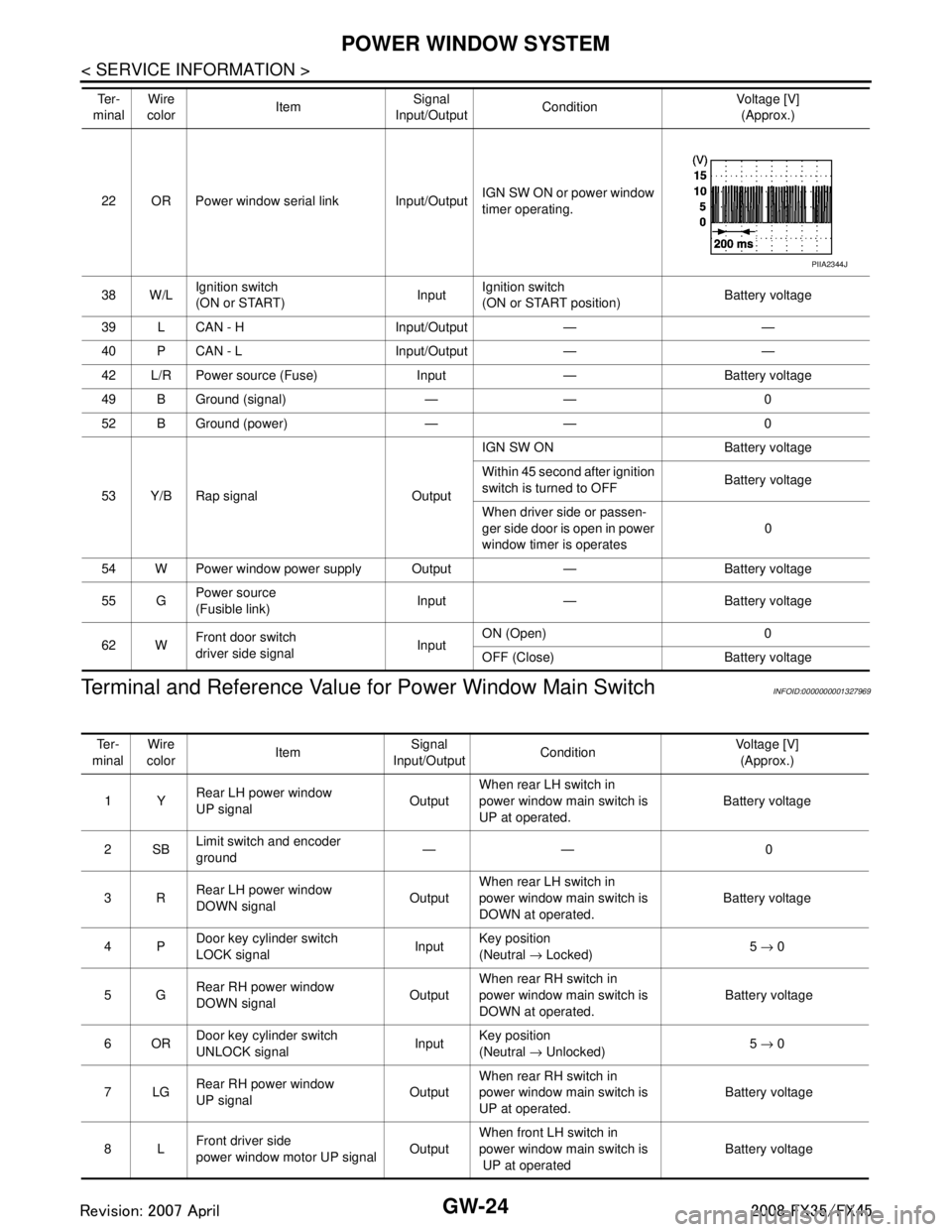
Terminal and Reference Value for Power Window Main Switch
INFOID:0000000001327969
22 OR Power window serial link Input/Output IGN SW ON or power window
timer operating.
38 W/L Ignition switch
(ON or START) InputIgnition switch
(ON or START position) Battery voltage
39 L CAN - H Input/Output — —
40 P CAN - L Input/Output — —
42 L/R Power source (Fuse) Input — Battery voltage
49 B Ground (signal) — — 0
52 B Ground (power) — — 0
53 Y/B Rap signal Output IGN SW ON Battery voltage
Within 45 second after ignition
switch is turned to OFF
Battery voltage
When driver side or passen-
ger side door is open in power
window timer is operates 0
54 W Power window power supply Output — Battery voltage
55 G Power source
(Fusible link)
Input — Battery voltage
62 W Front door switch
driver side signal InputON (Open) 0
OFF (Close) Battery voltage
Te r -
minal Wire
color Item Signal
Input/Output Condition Voltage [V]
(Approx.)
PIIA2344J
Te r -
minal Wire
color Item Signal
Input/Output Condition Voltage [V]
(Approx.)
1Y Rear LH power window
UP signal OutputWhen rear LH switch in
power window main switch is
UP at operated. Battery voltage
2SB Limit switch and encoder
ground —— 0
3R Rear LH power window
DOWN signal OutputWhen rear LH switch in
power window main switch is
DOWN at operated. Battery voltage
4P Door key cylinder switch
LOCK signal InputKey position
(Neutral
→ Locked) 5
→ 0
5G Rear RH power window
DOWN signal OutputWhen rear RH switch in
power window main switch is
DOWN at operated. Battery voltage
6OR Door key cylinder switch
UNLOCK signal Input
Key position
(Neutral
→ Unlocked) 5
→ 0
7LG Rear RH power window
UP signal OutputWhen rear RH switch in
power window main switch is
UP at operated. Battery voltage
8L Front driver side
power window motor UP signal
OutputWhen front LH switch in
power window main switch is
UP at operated
Battery voltage
3AA93ABC3ACD3AC03ACA3AC03AC63AC53A913A773A893A873A873A8E3A773A983AC73AC93AC03AC3
3A893A873A873A8F3A773A9D3AAF3A8A3A8C3A863A9D3AAF3A8B3A8C
Page 2940 of 3924
POWER WINDOW SYSTEMGW-27
< SERVICE INFORMATION >
C
DE
F
G H
J
K L
M A
B
GW
N
O P
Work FlowINFOID:0000000001327972
1. Check the symptom and customer's requests.
2. Understand the outline of system. Refer to GW-15, "
System Description"
3. According to the trouble diagnosis chart, repa ir or replace the cause of the malfunction.
Refer to GW-27, "
Trouble Diagnosis Symptom Chart".
4. Does power window system operate normally ? Yes, GO TO 5, If No, GO TO 3.
5. INSPECTION END
Trouble Diagnosis Symptom ChartINFOID:0000000001327973
Make sure other systems using the signal of the following systems operate normally.
DOOR SW–DR Indicates (ON / OFF) condition of front door switch driver side
DOOR SW–AS Indicates (ON / OFF) condition of front door switch passenger side
Symptom Repair order Refer to page
None of the power windows can be operated using any switch. 1. Check BCM power supply and ground circuit
GW-28
2. Check power window main switch power
supply and ground circuitGW-28
3. Check power window serial link
GW-45
Driver side power window alone does not operated. 1. Check front power wind
ow motor (driver side)
circuit GW-30
2. Replace power window main switch —
Front passenger side power window alone does not operated. 1. Check front power window switch (passenger
side) power and ground circuit
GW-30
2. Check power window serial link
GW-45
3. Check front power window motor (passenger
side) circuitGW-31
4. Replace BCM
BCS-13
Rear LH side power window alone does not operated Check rear power window motor (LH) circuit GW-32
Rear RH side power window alone does not operated Check rear power window motor (RH) circuitGW-34
Anti-pinch system does not operate normally (driver side)1. Door window sliding part malfunction
A foreign material adheres to window glass or
glass run rubber.
Glass run rubber wear or deformation.
Sash is tilted too much, or no enough. —
2. Limit switch adjusting GW-52
3. Check limit switch circuit (driver side)GW-36
4. Check encoder circuit (driver side) GW-39
Anti-pinch system does not operate normally (passenger side) 1. Door window sliding part malfunction
A foreign material adheres to window glass or
glass run rubber.
Glass run rubber wear or deformation.
Sash is tilted too much, or no enough. —
2. Limit switch adjusting GW-52
3. Check limit switch circuit (passenger side)GW-37
4. Check encoder circuit (passenger side)GW-40
Power window retained power operation does not operate properly 1. Check the retained power operation mode
setting.
GW-262. Check door switch
GW-42
3. Replace BCM.BCS-13
Does not operate by key cylinder switch 1. Check door key cylinder switch
GW-432. Replace power window main switch —
3AA93ABC3ACD3AC03ACA3AC03AC63AC53A913A773A893A873A873A8E3A773A983AC73AC93AC03AC3
3A893A873A873A8F3A773A9D3AAF3A8A3A8C3A863A9D3AAF3A8B3A8C
Page 2956 of 3924
POWER WINDOW SYSTEMGW-43
< SERVICE INFORMATION >
C
DE
F
G H
J
K L
M A
B
GW
N
O P
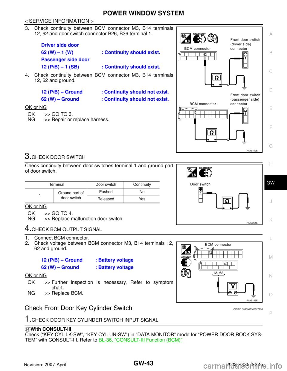
3. Check continuity between BCM connector M3, B14 terminals 12, 62 and door switch connector B26, B36 terminal 1.
4. Check continuity between BCM connector M3, B14 terminals 12, 62 and ground.
OK or NG
OK >> GO TO 3.
NG >> Repair or replace harness.
3.CHECK DOOR SWITCH
Check continuity between door switches terminal 1 and ground part
of door switch.
OK or NG
OK >> GO TO 4.
NG >> Replace malfunction door switch.
4.CHECK BCM OUTPUT SIGNAL
1. Connect BCM connector.
2. Check voltage between BCM connector M3, B14 terminals 12, 62 and ground.
OK or NG
OK >> Further inspection is necessary, Refer to symptom chart.
NG >> Replace BCM.
Check Front Door Key Cylinder SwitchINFOID:0000000001327986
1.CHECK DOOR KEY CYLINDER SWITCH INPUT SIGNAL
With CONSULT-III
Check (“KEY CYL LK-SW”, “KEY CYL UN-SW”) in “D ATA MONITOR” mode for “POWER DOOR ROCK SYS-
TEM” with CONSULT-III. Refer to BL-36, "
CONSULT-III Function (BCM)"
Driver side door
62 (W) – 1 (W) : Continuity should exist.
Passenger side door
12 (P/B) – 1 (SB) : Continuity should exist.
12 (P/B) – Ground : Contin uity should not exist.
62 (W) – Ground : Contin uity should not exist.
PIIA6159E
Terminal Door switch Continuity
1 Ground part of
door switch Pushed No
Released Yes
PIIA3351E
12 (P/B) – Ground : Battery voltage
62 (W) – Ground : Battery voltage
PIIA6158E
3AA93ABC3ACD3AC03ACA3AC03AC63AC53A913A773A893A873A873A8E3A773A983AC73AC93AC03AC3
3A893A873A873A8F3A773A9D3AAF3A8A3A8C3A863A9D3AAF3A8B3A8C
Page 2957 of 3924
GW-44
< SERVICE INFORMATION >
POWER WINDOW SYSTEM
Without CONSULT-III
1. Turn ignition switch OFF.
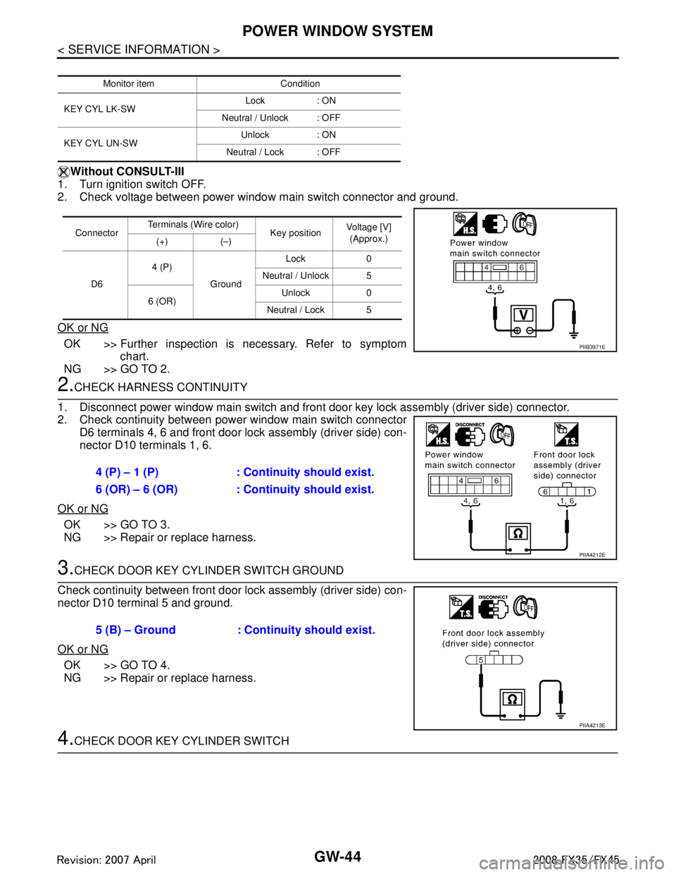
2. Check voltage between power window main switch connector and ground.
OK or NG
OK >> Further inspection is necessary. Refer to symptom chart.
NG >> GO TO 2.
2.CHECK HARNESS CONTINUITY
1. Disconnect power window main switch and front door key lock assembly (driver side) connector.
2. Check continuity between power window main switch connector D6 terminals 4, 6 and front door lock assembly (driver side) con-
nector D10 terminals 1, 6.
OK or NG
OK >> GO TO 3.
NG >> Repair or replace harness.
3.CHECK DOOR KEY CYLINDER SWITCH GROUND
Check continuity between front door lock assembly (driver side) con-
nector D10 terminal 5 and ground.
OK or NG
OK >> GO TO 4.
NG >> Repair or replace harness.
4.CHECK DOOR KEY CYLINDER SWITCH
Monitor item Condition
KEY CYL LK-SW Lock : ON
Neutral / Unlock : OFF
KEY CYL UN-SW Unlock : ON
Neutral / Lock : OFF
Connector Terminals (Wire color)
Key position Voltage [V]
(Approx.)
(+) (–)
D6 4 (P)
Ground Lock 0
Neutral / Unlock 5
6 (OR) Unlock 0
Neutral / Lock 5
PIIB3971E
4 (P) – 1 (P) : Conti nuity should exist.
6 (OR) – 6 (OR) : Cont inuity should exist.
PIIA4212E
5 (B) – Ground : Continuity should exist.
PIIA4213E
3AA93ABC3ACD3AC03ACA3AC03AC63AC53A913A773A893A873A873A8E3A773A983AC73AC93AC03AC3
3A893A873A873A8F3A773A9D3AAF3A8A3A8C3A863A9D3AAF3A8B3A8C
Page 2958 of 3924
POWER WINDOW SYSTEMGW-45
< SERVICE INFORMATION >
C
DE
F
G H
J
K L
M A
B
GW
N
O P
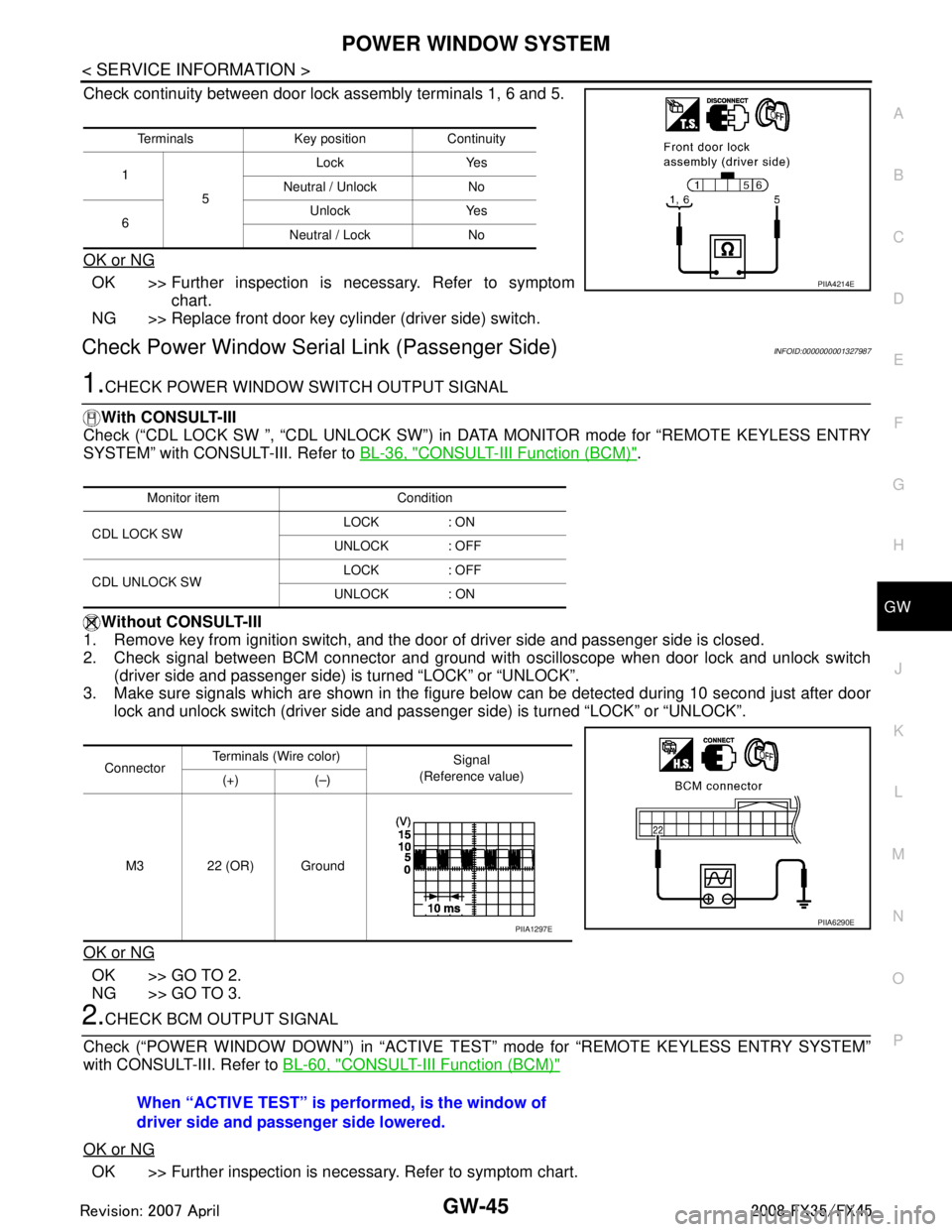
Check continuity between door lock assembly terminals 1, 6 and 5.
OK or NG
OK >> Further inspection is necessary. Refer to symptom chart.
NG >> Replace front door key cylinder (driver side) switch.
Check Power Window Serial Link (Passenger Side)INFOID:0000000001327987
1.CHECK POWER WINDOW SWITCH OUTPUT SIGNAL
With CONSULT-III
Check (“CDL LOCK SW ”, “CDL UNLOCK SW”) in DATA MONITOR mode for “REMOTE KEYLESS ENTRY
SYSTEM” with CONSULT-III. Refer to BL-36, "
CONSULT-III Function (BCM)".
Without CONSULT-III
1. Remove key from ignition switch, and the door of driver side and passenger side is closed.
2. Check signal between BCM connector and ground wit h oscilloscope when door lock and unlock switch
(driver side and passenger side) is turned “LOCK” or “UNLOCK”.
3. Make sure signals which are shown in the figure below can be detected during 10 second just after door
lock and unlock switch (driver side and passenger side) is turned “LOCK” or “UNLOCK”.
OK or NG
OK >> GO TO 2.
NG >> GO TO 3.
2.CHECK BCM OUTPUT SIGNAL
Check (“POWER WINDOW DOWN”) in “ACTIVE T EST” mode for “REMOTE KEYLESS ENTRY SYSTEM”
with CONSULT-III. Refer to BL-60, "
CONSULT-III Function (BCM)"
OK or NG
OK >> Further inspection is necessary. Refer to symptom chart.
Terminals Key position Continuity
1 5 Lock Yes
Neutral / Unlock No
6 Unlock Yes
Neutral / Lock No
PIIA4214E
Monitor item Condition
CDL LOCK SW LOCK : ON
UNLOCK : OFF
CDL UNLOCK SW LOCK : OFF
UNLOCK : ON
Connector Terminals (W
ire color)
Signal
(Reference value)
(+) (–)
M3 22 (OR) Ground
PIIA6290EPIIA1297E
When “ACTIVE TEST” is performed, is the window of
driver side and passenger side lowered.
3AA93ABC3ACD3AC03ACA3AC03AC63AC53A913A773A893A873A873A8E3A773A983AC73AC93AC03AC3
3A893A873A873A8F3A773A9D3AAF3A8A3A8C3A863A9D3AAF3A8B3A8C
Page 3021 of 3924

LAN-1
ELECTRICAL
C
DE
F
G H
I
J
L
M
SECTION LAN
A
B
LAN
N
O P
CONTENTS
LAN SYSTEM
CAN FUNDAMENTAL
SERVICE INFORMATION .. ..........................
3
PRECAUTIONS .............................................. .....3
Precaution for Trouble Diagnosis ........................ ......3
Precaution for Harness Repair ..................................3
SYSTEM DESCRIPTION .....................................4
CAN Communication System .............................. ......4
Diag on CAN .............................................................5
TROUBLE DIAGNOSIS ......................................7
Condition of Error Detection ................................ ......7
Symptom When Error Occurs in CAN Communi-
cation System ...................................................... ......
7
Self-Diagnosis .........................................................10
CAN Diagnostic Support Monitor ............................10
TROUBLE DIAGNOSES WORK FLOW ............13
Information Needed for Trouble Diagnosis ......... ....13
How to Use CAN Communication Signal Chart ......13
Trouble Diagnosis Flow Chart .................................14
Trouble Diagnosis Procedure ..................................14
CAN
SERVICE INFORMATION .. .........................
36
INDEX FOR DTC ............................................ ....36
DTC No. Index .................................................... ....36
HOW TO USE THIS SECTION ...........................37
Caution ................................................................ ....37
Abbreviation List ......................................................37
PRECAUTIONS ..................................................38
Precaution for Supplemental Restraint System
(SRS) "AIR BAG" and "SEAT BELT PRE-TEN-
SIONER" ............................................................. ....
38
Precaution for Trouble Diagnosis ............................38
Precaution for Harness Repair ................................38
TROUBLE DIAGNOSIS ....................................39
CAN Diagnostic Support Monitor ......................... ....39
CAN System Specification Chart .............................43
CAN Communication Signal Chart ..........................44
Schematic ................................................................54
Wiring Diagram - CAN - ...........................................55
Interview Sheet ........................................................58
Data Sheet ...............................................................58
CAN System (Type 1) ..............................................60
CAN System (Type 2) ..............................................61
CAN System (Type 3) ..............................................62
CAN System (Type 4) ..............................................63
CAN System (Type 5) ..............................................64
CAN System (Type 6) ..............................................65
CAN System (Type 7) ..............................................66
CAN system (Type 8) ..............................................67
Component Parts Location ......................................68
Harness Layout .......................................................68
Malfunction Area Chart ............................................68
Main Line Between TCM and Data Link Connector
....
69
Main Line Between Data Link Connector and Uni-
fied Meter and A/C Amp. .........................................
69
Main Line Between Unified Meter and A/C Amp.
and ABS Actuator and Electric Unit (Control Unit) ....
70
Main Line Between ABS Actu ator and Electric Unit
(Control Unit) and Driver Seat Control Unit .............
71
ECM Branch Line Circuit ..................................... ....72
AWD Control Unit Branch Line Circuit .....................72
Display Control Unit Branch Line Circuit .................73
ICC Unit Branch Line Circuit ................................ ....74
TCM Branch Line Circuit .........................................74
BCM Branch Line Circuit .........................................75
Data Link Connector Branch Line Circuit ................75
Intelligent Key Unit Branch Line Circuit ...................76
LDW Camera Unit Branch Line Circuit ....................76
Steering Angle Sensor Branch Line Circuit .............77
Unified Meter and A/C Amp. Branch Line Circuit ....78
ABS Actuator and Electric Unit (Control Unit)
Branch Line Circuit ..................................................
78
3AA93ABC3ACD3AC03ACA3AC03AC63AC53A913A773A893A873A873A8E3A773A983AC73AC93AC03AC3
3A893A873A873A8F3A773A9D3AAF3A8A3A8C3A863A9D3AAF3A8B3A8C
Page 3043 of 3924
![INFINITI FX35 2008 Service Manual
TROUBLE DIAGNOSES WORK FLOWLAN-23
< SERVICE INFORMATION > [CAN FUNDAMENTAL]
C
D
E
F
G H
I
J
L
M A
B
LAN
N
O P
c. Reception item of “AV”: “UNKWN” is not indicat ed. This indicates normal commu INFINITI FX35 2008 Service Manual
TROUBLE DIAGNOSES WORK FLOWLAN-23
< SERVICE INFORMATION > [CAN FUNDAMENTAL]
C
D
E
F
G H
I
J
L
M A
B
LAN
N
O P
c. Reception item of “AV”: “UNKWN” is not indicat ed. This indicates normal commu](/img/42/57017/w960_57017-3042.png)
TROUBLE DIAGNOSES WORK FLOWLAN-23
< SERVICE INFORMATION > [CAN FUNDAMENTAL]
C
D
E
F
G H
I
J
L
M A
B
LAN
N
O P
c. Reception item of “AV”: “UNKWN” is not indicat ed. This indicates normal communication between AV and
its receiving units. Do not draw any line.
d. Reception item of “BCM”: On “TCM”, “UNKWN” is indicated. This means BCM cannot receive the signal
from TCM. Draw a line to indicate an error between BCM and TCM (line 2-d in the figure below).
e. Reception item of “EPS” and “I-KEY”: “UNKWN” is not indicated. This indicates normal communication
between EPS and I-KEY and their receiving units. Do not draw any line.
NOTE:
PKID1215E
3AA93ABC3ACD3AC03ACA3AC03AC63AC53A913A773A893A873A873A8E3A773A983AC73AC93AC03AC3
3A893A873A873A8F3A773A9D3AAF3A8A3A8C3A863A9D3AAF3A8B3A8C