wheel INFINITI FX35 2008 Service Manual
[x] Cancel search | Manufacturer: INFINITI, Model Year: 2008, Model line: FX35, Model: INFINITI FX35 2008Pages: 3924, PDF Size: 81.37 MB
Page 3555 of 3924

FRONT OIL SEALRFD-13
< SERVICE INFORMATION >
CEF
G H
I
J
K L
M A
B
RFD
N
O P
5. Tighten to drive pinion lock nut, while adjust total preload torque.
CAUTION:
Adjust to the lower limit of the drive pinion lock nut tight-
ening torque first.
If the preload torque exceeds the specified value, replace
collapsible spacer and tighte n it again to adjust. Never
loosen drive pinion lock nut to adjust the preload torque.
6. Make a stamping for identificati on of front oil seal replacement
frequency. Refer to "IDENTIFICATION STAMP OF REPLACE-
MENT FREQUENCY OF FRONT OIL SEAL".
CAUTION:
Be sure to make a stamping after replacing front oil seal.
7. Install propeller shaft. Refer to PR-9, "
Removal and Installation".
8. Install side flange with the following procedure.
a. Attach the protector to side oil seal.
b. After the side flange is inserted and the serrated part of side gear has engaged the serrated part of flange, remove the pro-
tector.
c. Put a suitable drift on the center of side flange, then drive it until sound changes.
NOTE:
When installation is completed, driving sound of the side flange turns into a sound which seems to affect
the whole final drive.
d. Confirm that the dimension of the side flange installation (Mea- surement A) in the figure comes into the following.
9. Install drive shaft. Refer to RAX-10
.
10. Install rear wheel sensor. Refer to BRC-52
.
11. Install center muffler. Refer to EX-3
.
12. Refill gear oil to the final drive and check oil level. Refer to RFD-
9, "Changing Differential Gear Oil".
13. Check the final drive for oil leakage. Refer to RFD-9, "
Checking
Differential Gear Oil".
Tool number A: ST3127S000 (J-25765-A)
Drive pinion lock nut tightening torque:
147 - 323 N·m (15 - 32 kg-m, 109 - 238 ft-lb)
Total preload torque: Total preload torque should equal the measurement tak-
en during removal plus an ad ditional 0.1 - 0.4 N·m (0.01 -
0.04 kg-m, 1 - 3 in-lb).
Tool number : KV38107900 (J-39352)
PDIA0981E
SDIA0822E
Measurement A: 326 - 328 mm (12.83 - 12.91 in)
SDIA1039E
3AA93ABC3ACD3AC03ACA3AC03AC63AC53A913A773A893A873A873A8E3A773A983AC73AC93AC03AC3
3A893A873A873A8F3A773A9D3AAF3A8A3A8C3A863A9D3AAF3A8B3A8C
Page 3556 of 3924

RFD-14
< SERVICE INFORMATION >
SIDE OIL SEAL
SIDE OIL SEAL
Removal and InstallationINFOID:0000000001327498
REMOVAL
1. Remove center muffler with a power tool. Refer to EX-3.
2. Remove rear wheel sensor. Refer to BRC-52
.
3. Remove drive shaft from final drive. Then suspend it by wire etc. Refer to RAX-10
.
4. Install attachment to side flange, and then pull out the side flange with the sliding hammer.
For VQ35DE models
NOTE:
Circular clip installation position: Final drive side
For VK45DE models
NOTE:
Circular clip installation position: Final drive side
5. Remove side oil seal, using a flat-bladed screwdriver. CAUTION:
Be careful not to damage gear carrier.
INSTALLATION
1. Apply multi-purpose grease to side oil seal lips. Tool number A: KV40104100 ( — )
B: ST36230000 (J-25840-A)
SDIA1582E
Tool number A: KV40101000 ( — )B: ST36230000 (J-25840-A)
SDIA1583E
SDIA1584E
3AA93ABC3ACD3AC03ACA3AC03AC63AC53A913A773A893A873A873A8E3A773A983AC73AC93AC03AC3
3A893A873A873A8F3A773A9D3AAF3A8A3A8C3A863A9D3AAF3A8B3A8C
Page 3557 of 3924

SIDE OIL SEALRFD-15
< SERVICE INFORMATION >
CEF
G H
I
J
K L
M A
B
RFD
N
O P
2. Install side oil seal until it becomes flush with the case end, using the drift.
CAUTION:
Never reuse oil seal.
When installing, never incline oil seal.
3. Install side flange with the following procedure.
a. Attach the protector to side oil seal.
b. After the side flange is inserted and the serrated part of side gear has engaged the serrated part of flange, remove the pro-
tector.
c. Put a suitable drift on the center of side flange, then drive it until sound changes.
NOTE:
When installation is completed, driving sound of the side flange turns into a sound which seems to affect
the whole final drive.
d. Confirm that the dimension of the side flange installation (Mea- surement A) in the figure comes into the following.
4. Install drive shaft. Refer to RAX-10
.
5. Install rear wheel sensor. Refer to BRC-52
.
6. Install center muffler. Refer to EX-3, "
Component".
7. When oil leaks while removing, check oil level after the installa- tion. Refer to RFD-9
.
Tool number : KV38100200 (J-26233)
SDIA1585E
Tool number : KV38107900 (J-39352)
SDIA0822E
Measurement A: 326 - 328 mm (12.83 - 12.91 in)
SDIA1039E
3AA93ABC3ACD3AC03ACA3AC03AC63AC53A913A773A893A873A873A8E3A773A983AC73AC93AC03AC3
3A893A873A873A8F3A773A9D3AAF3A8A3A8C3A863A9D3AAF3A8B3A8C
Page 3558 of 3924

RFD-16
< SERVICE INFORMATION >
REAR FINAL DRIVE ASSEMBLY
REAR FINAL DRIVE ASSEMBLY
Removal and InstallationINFOID:0000000001327499
COMPONENTS
REMOVAL
1. Remove center muffler with a power tool. Refer to EX-3.
2. Remove rear stabilizer bar with a power tool. Refer to RSU-16
.
3. Remove propeller shaft from the final drive. Refer to PR-9, "
Removal and Installation".
4. Remove drive shaft from final drive with a power tool. Then sus- pend it by wire etc. Refer to RAX-10
.
5. Remove breather hose from the final drive.
6. Remove rear wheel sensor. Refer to BRC-52
.
7. Set a suitable jack to rear final drive assembly. CAUTION:
Never place a suitable jack on the rear cover (aluminum case).
1. Rear final drive assembly 2. Upper stopper 3. Propeller shaft
4. Washer 5. Lower stopper 6. Drive shaft
: For VQ35DE models
: For VK45DE models
Refer to GI-8, "
Component", for the symbols in the figure.
SDIA3563E
SDIA1094E
3AA93ABC3ACD3AC03ACA3AC03AC63AC53A913A773A893A873A873A8E3A773A983AC73AC93AC03AC3
3A893A873A873A8F3A773A9D3AAF3A8A3A8C3A863A9D3AAF3A8B3A8C
Page 3582 of 3924

RSU-1
SUSPENSION
C
DF
G H
I
J
K L
M
SECTION RSU
A
B
RSU
N
O PCONTENTS
REAR SUSPENSION
SERVICE INFORMATION .. ..........................2
PRECAUTIONS .............................................. .....2
Cautions .............................................................. ......2
PREPARATION ...................................................3
Special Service Tool ........................................... ......3
Commercial Service Tool ..........................................3
NOISE, VIBRATION AND HARSHNESS
(NVH) TROUBLESHOOTING .............................
4
NVH Troubleshooting Chart ................................ ......4
REAR SUSPENSION ASSEMBLY .....................5
On-Vehicle Inspection and Service ..................... ......5
Wheel AlignmentInspection .......................................5
Removal and Installation ...........................................6
SHOCK ABSORBER ..........................................9
Removal and Installation ..................................... ......9
Disassembly and Assembly ......................................9
SUSPENSION ARM ..........................................11
Removal and Installation ..................................... ....11
RADIUS ROD ................................... .................13
Removal and Installation ..................................... ....13
FRONT LOWER LINK .......................................14
Removal and Installation .........................................14
REAR LOWER LINK & COIL SPRING .............15
Removal and Installation .........................................15
STABILIZER BAR .............................................16
Removal and Installation .........................................16
REAR SUSPENSION MEMBER .......................17
Removal and Installation ..................................... ....17
SERVICE DATA AND SPECIFICATIONS
(SDS) .................................................................
18
Wheel Alignment (Unladen*) ...................................18
Ball Joint ..................................................................18
Wheelarch Height (Unladen*) ..................................18
3AA93ABC3ACD3AC03ACA3AC03AC63AC53A913A773A893A873A873A8E3A773A983AC73AC93AC03AC3
3A893A873A873A8F3A773A9D3AAF3A8A3A8C3A863A9D3AAF3A8B3A8C
Page 3583 of 3924

RSU-2
< SERVICE INFORMATION >
PRECAUTIONS
SERVICE INFORMATION
PRECAUTIONS
CautionsINFOID:0000000001327548
• When installing rubber bushings, final tightening must be carried out under unladen conditions with tires on
level ground. Oil will shorten the life of rubber bushings. Be sure to wipe off any spilled oil.
Unladen conditions means that fuel, engine coolant and lubricant are full. Spare tire, jack, hand tools and
mats are in designated positions.
After servicing suspension parts, be sure to check wheel alignment.
Caulking nuts are not reusable. Always use new ones w hen installing. Since new caulking nuts are pre-oiled,
tighten as they are.
3AA93ABC3ACD3AC03ACA3AC03AC63AC53A913A773A893A873A873A8E3A773A983AC73AC93AC03AC3
3A893A873A873A8F3A773A9D3AAF3A8A3A8C3A863A9D3AAF3A8B3A8C
Page 3585 of 3924

RSU-4
< SERVICE INFORMATION >
NOISE, VIBRATION AND HARSHNESS (NVH) TROUBLESHOOTING
NOISE, VIBRATION AND HARSHNESS (NVH) TROUBLESHOOTING
NVH Troubleshooting ChartINFOID:0000000001327551
Use chart below to help you find the cause of the symp tom. If necessary, repair or replace these parts.
×: ApplicableReference page
RSU-6RSU-9—
—
—
RSU-6FSU-5RSU-16
NVH in PR section
NVH in RFD section
NVH in RAX and RSU section
NVH in WT section
NVH in WT section
NVH in RAX section
NVH in BR sectionNVH in PS section
Possible cause and SUSPECTED PARTS
Improper installation, looseness
Shock absorber deformation, damage or deflection
Bushing or mounting deterioration
Parts interference
Spring fatigue
Suspension looseness
Incorrect wheel alignment
Stabilizer bar fatigue
PROPELLER SHAFT
DIFFERENTIAL
REAR AXLE AND REAR SUSPENSION
TIRE
ROAD WHEEL
DRIVE SHAFT
BRAKE
STEERING
Symptom REAR SUSPENSION Noise
×××××× ××××××××
Shake ×××× × × ××××××
Vibration ××××× × ×× × ×
Shimmy ×××× × ××× ××
Judder ××× ××× ××
Poor quality ride or
handling ××××× ×× ×××
3AA93ABC3ACD3AC03ACA3AC03AC63AC53A913A773A893A873A873A8E3A773A983AC73AC93AC03AC3
3A893A873A873A8F3A773A9D3AAF3A8A3A8C3A863A9D3AAF3A8B3A8C
Page 3586 of 3924

REAR SUSPENSION ASSEMBLYRSU-5
< SERVICE INFORMATION >
C
DF
G H
I
J
K L
M A
B
RSU
N
O P
REAR SUSPENSION ASSEMBLY
On-Vehicle Inspection and ServiceINFOID:0000000001327552
Make sure the mounting conditions (looseness, ba ck lash) of each component and component status (wear,
damage) are normal.
INSPECTION OF BALL JOINT END PLAY
Measure axial end play by installing and moving up/down with an
iron pry bar or something similar between suspension arm and axle.
CAUTION:
Be careful not to damage ball joint boot.
SHOCK ABSORBER INSPECTION
Check shock absorber for oil leakage, damage and replace if necessary.
Wheel AlignmentInspectionINFOID:0000000001327553
DESCRIPTION
Measure wheel alignment under unladen conditions. “U nladen conditions” means that fuel, engine coolant,
and lubricant are full. Spare tire, jack, hand tools and mats in designated positions.
PRELIMINARY INSPECTION
Check tires for improper air pressure and wear.
Check road wheels for runout.
Check wheel bearing axial end play.
Check ball joint axial end play of suspension arm.
Check shock absorber operation.
Check each mounting point of axle and suspension for looseness and deformation.
Check each link, arm and member for cracks, deformation, and other damage.
Check vehicle posture.
GENERAL INFORMATION AND RECOMMENDATIONS
A four-wheel thrust alignment should be performed.
- This type of alignment is recomm ended for any NISSAN/INFINITI vehicle.
- The four-wheel “thrust” process helps ensure that t he vehicle is properly aligned and the steering wheel is
centered.
- The alignment rack itself should be capable of accepting any NISSAN/INFINITI vehicle.
- The rack should be checked to ensure that it is level.
Make sure the machine is properly calibrated.
- Your alignment equipment should be regularly ca librated in order to give correct information.
- Check with the manufacturer of your specific equi pment for their recommended Service/Calibration Sched-
ule.
THE ALIGNMENT PROCESS
IMPORTANT:
Use only the alignment specificati ons listed in this Service Manual.
When displaying the alignment settings, many alignment machines use “indicators”: (Green/red, plus or
minus, Go/No Go). Do NOT use these indicators.
- The alignment specifications programmed into your machine that operate these indicators may not be cor-
rect.
- This may result in an ERROR.
Some newer alignment machines are equipped with an optional “Rolling Compensation” method to “com-
pensate” the sensors (alignment targets or head units). DO NOT use this “Rolling Compensation”
method. Standard value
Axial end play : 0 mm (0 in)
SEIA0245J
3AA93ABC3ACD3AC03ACA3AC03AC63AC53A913A773A893A873A873A8E3A773A983AC73AC93AC03AC3
3A893A873A873A8F3A773A9D3AAF3A8A3A8C3A863A9D3AAF3A8B3A8C
Page 3587 of 3924

RSU-6
< SERVICE INFORMATION >
REAR SUSPENSION ASSEMBLY
- Use the “Jacking Compensation Method”. After installing the alignment targets or head units, raise the vehi-
cle and rotate the wheels 1/2 turn both ways.
- See Instructions in the alignment machine you're using for more information on this.
CAMBER INSPECTION
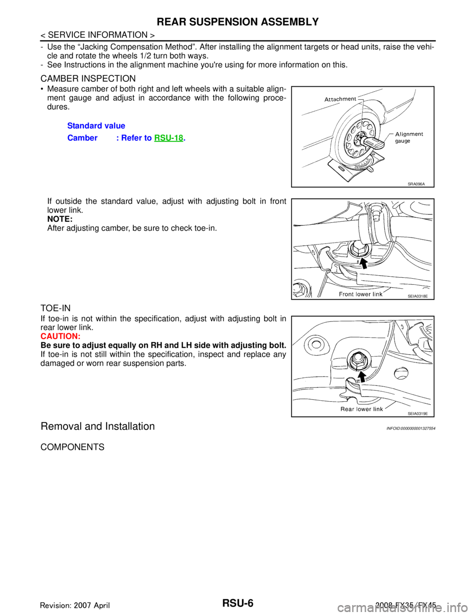
Measure camber of both right and left wheels with a suitable align-
ment gauge and adjust in accordance with the following proce-
dures.
If outside the standard value, adjust with adjusting bolt in front
lower link.
NOTE:
After adjusting camber, be sure to check toe-in.
TOE-IN
If toe-in is not within the specif ication, adjust with adjusting bolt in
rear lower link.
CAUTION:
Be sure to adjust equally on RH and LH side with adjusting bolt.
If toe-in is not still within the specification, inspect and replace any
damaged or worn rear suspension parts.
Removal and InstallationINFOID:0000000001327554
COMPONENTS
Standard value
Camber : Refer to RSU-18
.
SRA096A
SEIA0318E
SEIA0319E
3AA93ABC3ACD3AC03ACA3AC03AC63AC53A913A773A893A873A873A8E3A773A983AC73AC93AC03AC3
3A893A873A873A8F3A773A9D3AAF3A8A3A8C3A863A9D3AAF3A8B3A8C
Page 3589 of 3924

RSU-8
< SERVICE INFORMATION >
REAR SUSPENSION ASSEMBLY
REMOVAL
1. Remove tires from vehicle with power tool.
2. Remove brake caliper with power tool. Hang it in a place where it will not interfere with work. Refer to BR-
24.
NOTE:
Avoid depressing brake pedal while brake caliper is removed.
3. Remove wheel sensor from rear final drive, t hen remove wheel sensor harness from rear suspension
member.
4. Remove height sensor harness from rear suspension member (if equipped).
5. Remove center muffler and main muffler. Refer to EX-3, "
Component".
6. Remove stabilizer bar. Refer to RSU-16, "
Removal and Installation".
7. Remove rear propeller shaft. Refer to PR-9, "
Removal and Installation".
8. Separate attachments between parking brake cable and vehicle and rear suspension member.
9. Remove rear lower link and coil spring. Refer to RSU-14, "
Removal and Installation".
10. Remove fixing bolt in lower side of shock absorber with power tool.
11. Set jack under rear final drive.
12. Remove fixing bolts and nuts of tunnel stay and mem ber stay with power tool, then remove those parts
from vehicle.
13. Remove fixing bolts and nuts of rear pin stay with pow er tool and then remove rear pin stay from vehicle.
14. Gradually lowering jack, remove rear suspension assembly.
INSTALLATION
Refer to "Removal and installation" for tightening torque. Install in the reverse order of removal.
NOTE:
Refer to component parts location and do not reuse non-reusable parts.
Perform final tightening of installation position of links (rubber bushing) under unladen conditions with tires on level ground. Check wheel alignment. Refer to RSU-5, "
Wheel AlignmentInspection".
After adjusting wheel alignment, adjust neutral position of steering angle sensor. Refer to BRC-8, "
Adjust-
ment of Steering Angle Sensor Neutral Position".
19. Suspension arm 20. Stabilizer connecting rod mounting
bracket21. Stabilizer connecting rod
22. Rear pin stay 23. Rear suspension member 24. Stabilizer bar
25. Stabilizer bushing 26. Stabilizer clamp 27. Member stay
28. Tunnel stay A: With height sensor B: Without height sensor
Refer to GI-8, "
Component", for the symbols in the figure.
3AA93ABC3ACD3AC03ACA3AC03AC63AC53A913A773A893A873A873A8E3A773A983AC73AC93AC03AC3
3A893A873A873A8F3A773A9D3AAF3A8A3A8C3A863A9D3AAF3A8B3A8C