drain bolt INFINITI FX35 2008 Owner's Manual
[x] Cancel search | Manufacturer: INFINITI, Model Year: 2008, Model line: FX35, Model: INFINITI FX35 2008Pages: 3924, PDF Size: 81.37 MB
Page 513 of 3924

ATC-108
< SERVICE INFORMATION >
HEATER & COOLING UNIT ASSEMBLY
HEATER & COOLING UNIT ASSEMBLY
Removal and InstallationINFOID:0000000001328211
REMOVAL
1. Use a refrigerant collecting equipment (for HFC-134a) to discharge the refrigerant.
2. Drain coolant from cooling system. Refer to CO-10, "
Changing Engine Coolant" (VQ35DE) or CO-37,
"Changing Engine Coolant" (VK45DE).
3. Remove cowl top cover. Refer to EI-23
.
4. Remove high-pressure pipe 2 mounting clip.
5. Remove low-pressure flexible hose bracket mounting bolt. Refer to ATC-128, "
Removal and Installation of
Low-Pressure Flexible Hose".
6. Disconnect low-pressure pipe 1 and high-pressure pipe 2 from evaporator.
a. Set a disconnector [high-pressure side (SST: 9253089908), low- pressure side (SST: 9253089916)] on A/C piping.
b. Slide a disconnector toward vehicle front until it clicks.
c. Slide A/C piping toward vehicle front and disconnect it. CAUTION:
Cap or wrap the joint of low- pressure pipe 1, 2 and high-
pressure pipe 2, 3 with suitab le material such as vinyl tape
to avoid the entry of air.
7. Remove electric throttle control actuator (VQ35DE). Refer to EM-19
.
8. Disconnect two heater hoses from heater core.
9. Remove instrument panel and pad. Refer to IP-10
.
10. Remove blower unit. Refer to ATC-103
.
RJIA2037E
RJIA2077E
RJIA2041E
3AA93ABC3ACD3AC03ACA3AC03AC63AC53A913A773A893A873A873A8E3A773A983AC73AC93AC03AC3
3A893A873A873A8F3A773A9D3AAF3A8A3A8C3A863A9D3AAF3A8B3A8C
Page 514 of 3924
HEATER & COOLING UNIT ASSEMBLYATC-109
< SERVICE INFORMATION >
C
DE
F
G H
I
K L
M A
B
AT C
N
O P
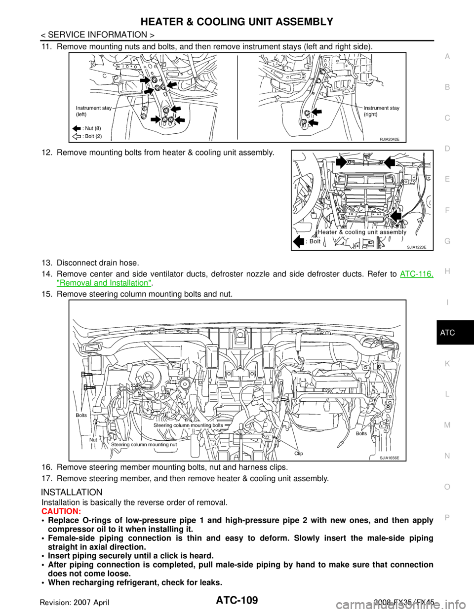
11. Remove mounting nuts and bolts, and then remove instrument stays (left and right side).
12. Remove mounting bolts from heater & cooling unit assembly.
13. Disconnect drain hose.
14. Remove center and side ventilator ducts, defroster nozzle and side defroster ducts. Refer to ATC-116,
"Removal and Installation".
15. Remove steering column mounting bolts and nut.
16. Remove steering member mounting bolts, nut and harness clips.
17. Remove steering member, and then remove heater & cooling unit assembly.
INSTALLATION
Installation is basically the reverse order of removal.
CAUTION:
Replace O-rings of low-pressure pipe 1 and high- pressure pipe 2 with new ones, and then apply
compressor oil to it when installing it.
Female-side piping c onnection is thin and easy to deform. Slowly insert the male-side piping
straight in axial direction.
Insert piping securely until a click is heard.
After piping connection is comple ted, pull male-side piping by hand to make sure that connection
does not come loose.
When recharging refrigerant, check for leaks.
RJIA2042E
SJIA1223E
SJIA1656E
3AA93ABC3ACD3AC03ACA3AC03AC63AC53A913A773A893A873A873A8E3A773A983AC73AC93AC03AC3
3A893A873A873A8F3A773A9D3AAF3A8A3A8C3A863A9D3AAF3A8B3A8C
Page 543 of 3924

ATC-138
< SERVICE INFORMATION >
REFRIGERANT LINES
O-rings are different from low-pressure pipe 1 (high-pressure pipe 2) and low-pressure pipe 2 (high-
pressure pipe 3).
Mark the mounting position of intake sensor bracket prior to removal so that the reinstalled sensor
can be located in the same position.
When recharging refrigerant, check for leaks.
Removal and Installation of Expansion ValveINFOID:0000000001328230
REMOVAL
1. Remove evaporator. Refer to ATC-137, "Removal and Installation of Evaporator".
2. Remove mounting bolts, and then remove expansion valve. CAUTION:
Cap or wrap the joint of evaporator with suitable material
such as vinyl tape to avoid the entry of air.
INSTALLATION
Installation is basically the reverse order of removal.
CAUTION:
Replace O-rings of evaporator with new ones, and then apply compressor oil to it when installing it.
O-rings are different from low-pressure pipe 1 (h igh-pressure pipe 2) and low-pressure pipe 2 (high-
pressure pipe 3).
When recharging refrigerant, check for leaks.
Checking of Refrigerant LeaksINFOID:0000000001328231
Perform a visual inspection of all refrigeration parts, fittings, hoses and components for signs of A/C lubricant
leakage, damage and corrosion. A/C lubricant leakage ma y indicate an area of refrigerant leakage. Allow
extra inspection time in these areas when using either an electrical leak detector or fluorescent dye leak
detector (SST: J-42220).
If dye is observed, c onfirm the leak with an electrical leak detector. It is possible a prior leak was repaired and
not properly cleaned.
When searching for leaks, do not stop when one leak is found but continue to check for additional leaks at all
system components and connections.
When searching for refrigerant leaks using an electric al leak detector, move the probe along the suspected
leak area at 1 to 2 inches per second and no further than 1/4 inch from the component.
CAUTION:
Moving the electrical leak detector probe slower and closer to the suspected leak area will improve the
chances of finding a leak.
Checking System for Leaks Using the Fluore scent Leak DetectorINFOID:0000000001328232
1. Check A/C system for leaks using the UV lamp and safety goggles (SST: J-42220) in a low sunlight area
(area without windows preferable). Illuminate all co mponents, fittings and lines. The dye will appear as a
bright green/yellow area at the point of leakage. Fluorescent dye observed at the evaporator drain open-
ing indicates an evaporator core assembly (tubes, core or expansion valve) leak.
2. If the suspected area is difficult to see, use an adjustable mirror or wipe the area with a clean shop rag or
cloth, with the UV lamp for dye residue.
3. After the leak is repaired, remove any residual dye using dye cleaner (SST: J-43872) to prevent future
misdiagnosis. Low-pressure pipe 1 bracket mounting bolt
: 5.5 N·m (0.56 kg-m, 49 in-lb)
RJIA1864E
3AA93ABC3ACD3AC03ACA3AC03AC63AC53A913A773A893A873A873A8E3A773A983AC73AC93AC03AC3
3A893A873A873A8F3A773A9D3AAF3A8A3A8C3A863A9D3AAF3A8B3A8C
Page 994 of 3924

BR-10
< SERVICE INFORMATION >
BRAKE TUBE AND HOSE
BRAKE TUBE AND HOSE
Hydraulic CircuitINFOID:0000000001327613
CAUTION:
All brake hoses and tubes must be free from excessive bending, twisting and pulling.
Make sure there is no interference with other part s when turning steering both clockwise and coun-
terclockwise.
The brake tubes and hoses is an important safety pa rt. If a brake fluid leak is detected, always disas-
semble the parts. Replace applicable part with a new one, if necessary.
Be careful not to splash brake fluid on painted areas; it way cause paint damage. If brake fluid is
splashed on painted surfaces of bo dy, immediately wipe it off and them wash it away with water
immediately.
Do not bend or twist brake hose sharply, or strongly pull it.
When removing components, cover br ake line connections so that no dirt, no dust, or other foreign
matter gets in.
Refill with new brake fluid “ DOT 3 ”.
Do not reuse drained brake fluid.
Removal and Installation of Fr ont Brake Tube and Brake HoseINFOID:0000000001327614
REMOVAL
1. Drain brake fluid. Refer to BR-8, "Drain and Refill".
2. Using a flare nut wrench, remove brake tube from brake hose.
3. Remove union bolt and remove brake hose from caliper assembly.
4. Remove lock plate and remove brake hose from vehicle.
INSTALLATION
1. Position brake hose by aligning with the protrusion on caliper assembly, and them tighten union bolt to the specified torque.
CAUTION:
Do not reuse copper washer.
2. Install brake hose to brake tube. Temporarily tighten flare nut by hand as much as possible. Secure them it to bracket with lock
plate.
3. Using a flare nut torque wrench, tighten flare nut to the specified
torque.
4. Refill brake fluid and bleed air. Refer to BR-8, "
Bleeding Brake
System".
PFIA0818E
SFIA1204E
3AA93ABC3ACD3AC03ACA3AC03AC63AC53A913A773A893A873A873A8E3A773A983AC73AC93AC03AC3
3A893A873A873A8F3A773A9D3AAF3A8A3A8C3A863A9D3AAF3A8B3A8C
Page 995 of 3924
BRAKE TUBE AND HOSEBR-11
< SERVICE INFORMATION >
C
DE
G H
I
J
K L
M A
B
BR
N
O P
Removal and Installation of R ear Brake Piping and Brake HoseINFOID:0000000001327615
REMOVAL
1. Drain brake fluid. Refer to BR-8, "Drain and Refill".
2. Using a flare nut wrench, remove brake tube from brake hose.
3. Remove union bolt, and then remove brake hose from caliper assembly.
4. Remove lock nut plate and remove brake hose from vehicle.
INSTALLATION
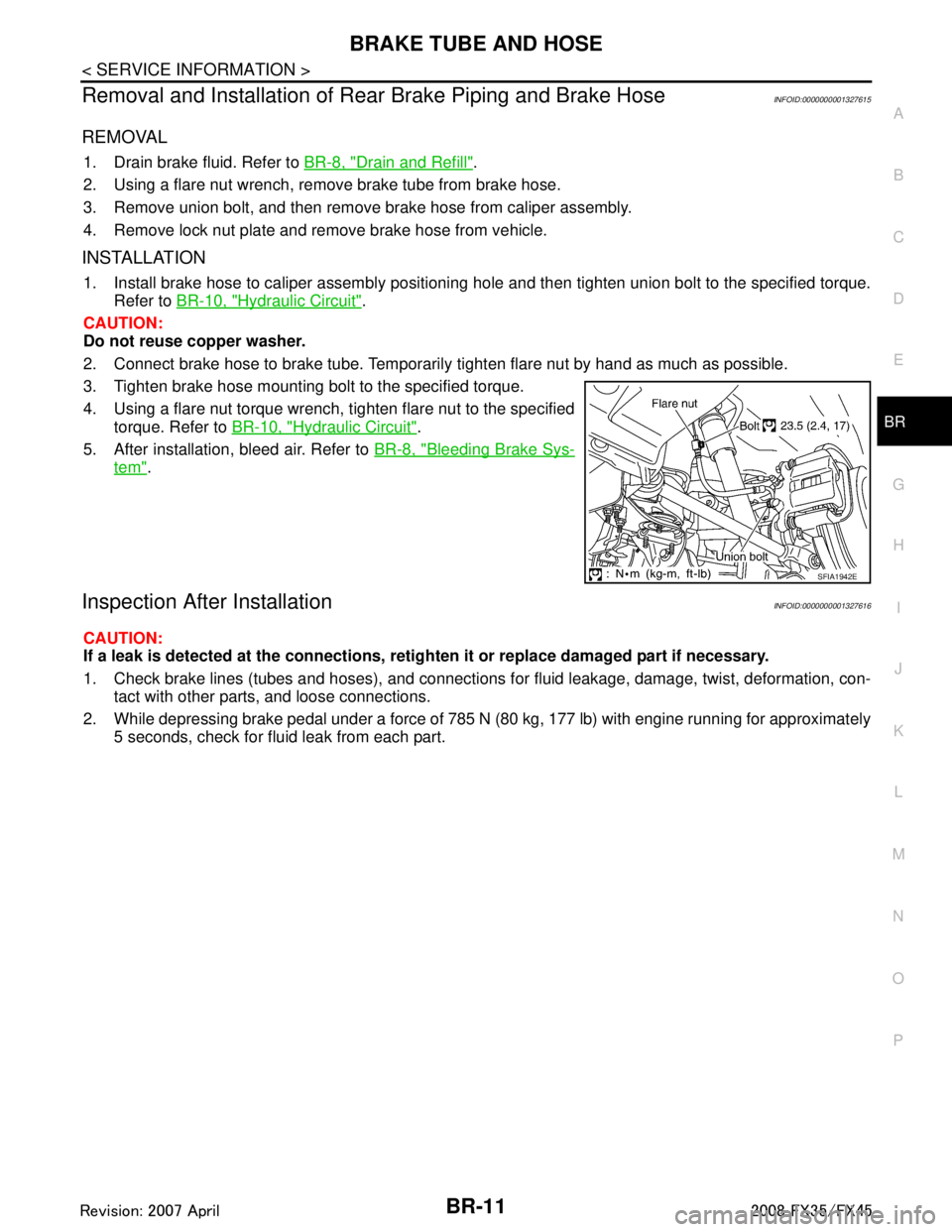
1. Install brake hose to caliper assembly positioni ng hole and then tighten union bolt to the specified torque.
Refer to BR-10, "
Hydraulic Circuit".
CAUTION:
Do not reuse copper washer.
2. Connect brake hose to brake tube. Temporarily tighten flare nut by hand as much as possible.
3. Tighten brake hose mounting bolt to the specified torque.
4. Using a flare nut torque wrench, tighten flare nut to the specified torque. Refer to BR-10, "
Hydraulic Circuit".
5. After installation, bleed air. Refer to BR-8, "
Bleeding Brake Sys-
tem".
Inspection After InstallationINFOID:0000000001327616
CAUTION:
If a leak is detected at the connections, re tighten it or replace damaged part if necessary.
1. Check brake lines (tubes and hoses), and connections for fluid leakage, damage, twist, deformation, con-
tact with other parts, and loose connections.
2. While depressing brake pedal under a force of 785 N (80 kg, 177 lb) with engine running for approximately 5 seconds, check for fluid leak from each part.
SFIA1942E
3AA93ABC3ACD3AC03ACA3AC03AC63AC53A913A773A893A873A873A8E3A773A983AC73AC93AC03AC3
3A893A873A873A8F3A773A9D3AAF3A8A3A8C3A863A9D3AAF3A8B3A8C
Page 1003 of 3924

FRONT DISC BRAKEBR-19
< SERVICE INFORMATION >
C
DE
G H
I
J
K L
M A
B
BR
N
O P
While removing cylinder body, never depr ess brake pedal because piston will pop out.
It is not necessary to remove bolts on torq ue member and brake hose except for disassembly or
replacement of caliper assembly. In this case, suspe nd cylinder body with wire so as not to stretch
brake hose.
Do not damage piston boot.
If any shim is subject to serious corrosion, replace it with a new one.
Always replace shims and shim covers as a set when replacing brake pads.
Keep rotor clean, from brake fluid.
Burnish brake contact surface after refinishing or replacing rotors, after replacing pads, or it a soft
pedal occurs at very low mileage. Refer to BR-23, "
Brake Burnishing Procedure".
Removal and Installation of Brake PadINFOID:0000000001327629
REMOVAL
1. Remove tires from vehicle with power tool.
2. Remove lower sliding pin bolt.
3. Hang cylinder body with a wire, and remove pads, pad retainers,
shims from torque member.
CAUTION:
When removing pad retainer from torque member, lift pad
retainer in the direction show n by arrow (shown in the fig-
ure) so as not to deform it.
INSTALLATION
1. Apply PBC (Poly Butyl Cuprysil) or silicone-based grease to the both sides of inner shim and outer shim, install inner shim and
inner shim cover to inner pad, and outer shim and outer shim
cover to outer pad.
2. Apply PBC (Poly Butyl Cuprysil) or silicone-based grease to pad contact surface on pad retainers, and install pad retainers and
pads to torque member.
CAUTION:
Inner pad and outer pad have pad-return mechanism on
upper side of pad retainer. When installing pad to torque
member, be sure to install pad return lever to pad wear sen-
sor securely.
3. Install cylinder body to torque member. CAUTION:
When replacing pads with new ones, press in piston until pads can be installed. In this case, care-
fully monitor brake fluid level in reservoir tank because brake fluid will return to master cylinder
reservoir tank.
4. Install lower sliding pin bolt, and tighten it to the specified torque. Refer to BR-18, "
Component".
5. Secure disc rotor with wheel nuts. Depress brake pedal a few times until it gets a responsive touch.
6. Check brake for drag.
7. Install tires to vehicle.
Removal and Installation of Brake Caliper AssemblyINFOID:0000000001327630
REMOVAL
1. Remove tires from vehicle with power tool.
2. Fasten disc rotor using wheel nut.
3. Drain brake fluid. Refer to BR-8, "
Drain and Refill".
SBR556E
SBR557E
3AA93ABC3ACD3AC03ACA3AC03AC63AC53A913A773A893A873A873A8E3A773A983AC73AC93AC03AC3
3A893A873A873A8F3A773A9D3AAF3A8A3A8C3A863A9D3AAF3A8B3A8C
Page 1004 of 3924
BR-20
< SERVICE INFORMATION >
FRONT DISC BRAKE
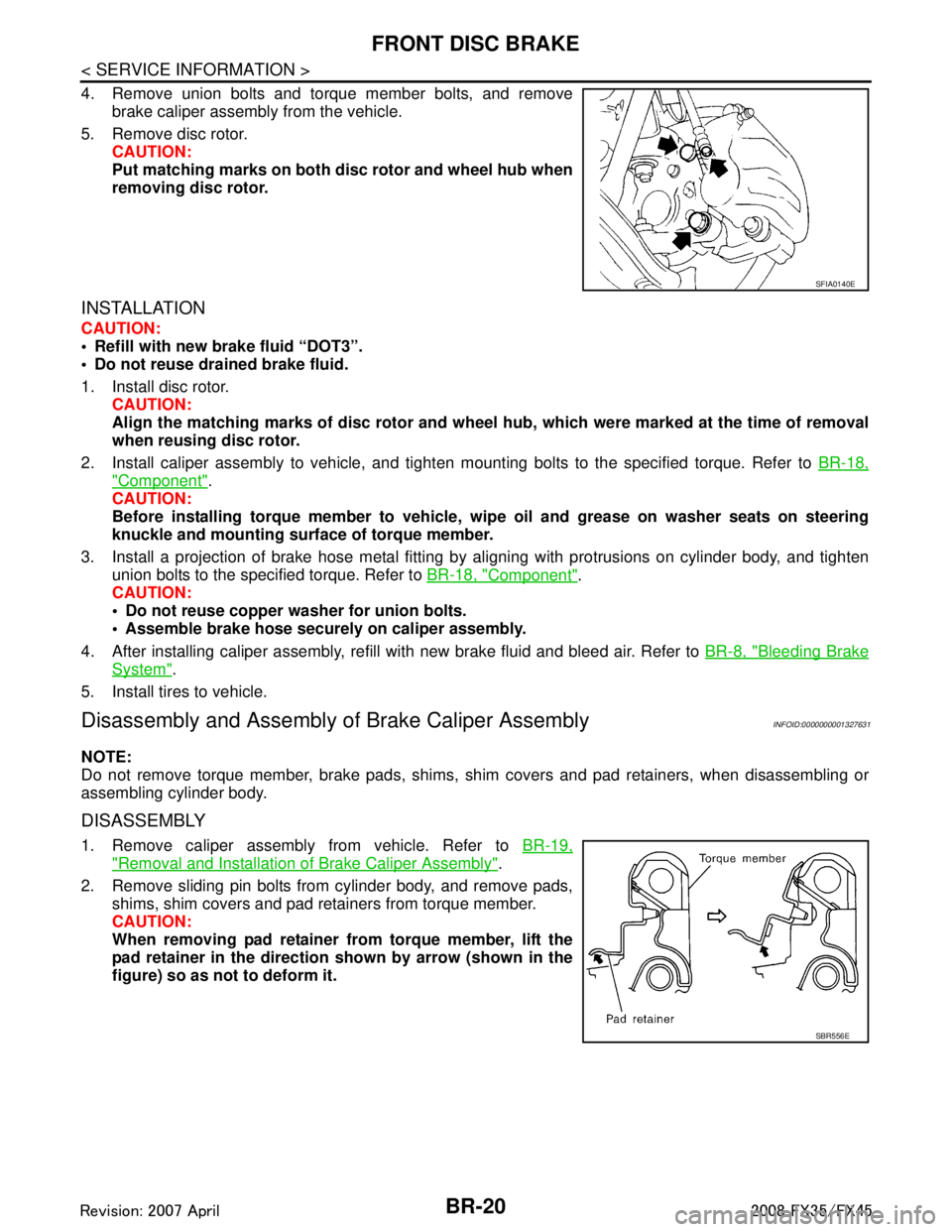
4. Remove union bolts and torque member bolts, and removebrake caliper assembly from the vehicle.
5. Remove disc rotor. CAUTION:
Put matching marks on both disc rotor and wheel hub when
removing disc rotor.
INSTALLATION
CAUTION:
Refill with new brake fluid “DOT3”.
Do not reuse drained brake fluid.
1. Install disc rotor.
CAUTION:
Align the matching marks of disc rotor and wheel hub, which were marked at the time of removal
when reusing disc rotor.
2. Install caliper assembly to vehicle, and tighten mounting bolts to the specified torque. Refer to BR-18,
"Component".
CAUTION:
Before installing torque member to vehicle, wipe oil and grease on washer seats on steering
knuckle and mounting surface of torque member.
3. Install a projection of brake hose metal fitting by aligning with protrusions on cylinder body, and tighten
union bolts to the specified torque. Refer to BR-18, "
Component".
CAUTION:
Do not reuse copper washer for union bolts.
Assemble brake hose securely on caliper assembly.
4. After installing caliper assembly, refill with new brake fluid and bleed air. Refer to BR-8, "
Bleeding Brake
System".
5. Install tires to vehicle.
Disassembly and Assembly of Brake Caliper AssemblyINFOID:0000000001327631
NOTE:
Do not remove torque member, brake pads, shims, shim covers and pad retainers, when disassembling or
assembling cylinder body.
DISASSEMBLY
1. Remove caliper assembly from vehicle. Refer to BR-19,
"Removal and Installation of Brake Caliper Assembly".
2. Remove sliding pin bolts from cylinder body, and remove pads, shims, shim covers and pad retainers from torque member.
CAUTION:
When removing pad retainer fr om torque member, lift the
pad retainer in the direction shown by arrow (shown in the
figure) so as not to deform it.
SFIA0140E
SBR556E
3AA93ABC3ACD3AC03ACA3AC03AC63AC53A913A773A893A873A873A8E3A773A983AC73AC93AC03AC3
3A893A873A873A8F3A773A9D3AAF3A8A3A8C3A863A9D3AAF3A8B3A8C
Page 1009 of 3924

REAR DISC BRAKEBR-25
< SERVICE INFORMATION >
C
DE
G H
I
J
K L
M A
B
BR
N
O P
WARNING:
Clean dust on caliper and brake pad with a vacuum du st collector to minimize the hazard of airborne
particles or other materials.
CAUTION:
While removing cylinder body, never depr ess brake pedal because piston will pop out.
It is not necessary to remove bolts on torq ue member and brake hose except for disassembly or
replacement of caliper assembly. In this case, hang cylinder body with a wire so as not to stretch
brake hose.
Do not damage piston boot.
If any shim is subject to serious corrosion, replace it with a new one.
Always replace shims and shim covers as a set when replacing brake pads.
Keep rotor clean, from brake fluid.
Burnish brake contact surface after refinishing or replacing rotors, after replacing pads, or if a soft
pedal occurs at very low mileage. Refer to BR-29, "
Brake Burnishing Procedure".
Removal and Installation of Brake PadINFOID:0000000001327635
REMOVAL
1. Remove tires from vehicle with power tool.
2. Remove sliding pin bolt (one on top).
3. Suspend cylinder body with a wire, and remove pads, pad retainers, shim from torque member.
INSTALLATION
1. Apply PBC (Poly Butyl Cuprysil) grease or silic one-based grease to the backside of pad and to both sides
of shim, and install inner shim and shim cover to inner pad, and install the outer shim to outer pad.
2. Install pad retainer and mount pad assemblies to torque member.
3. Push piston in so that pad is firmly installed and mount cylinder body to torque member. CAUTION:
When replacing pads with new ones, press in piston until pads can be installed. In this case, care-
fully monitor brake fluid level in reservoir tank because brake fluid will return to master cylinder
reservoir tank.
4. Install sliding pin bolt (one on top) and tighten to the specified torque. Refer to BR-24, "
Component".
5. Check brake for drag.
6. Install tires to the vehicle.
Removal and Installation of Brake Caliper AssemblyINFOID:0000000001327636
REMOVAL
1. Remove tires from vehicle with power tool.
2. Fasten disc rotor using wheel nut.
3. Drain brake fluid. Refer to BR-8, "
Drain and Refill".
4. Remove union bolt and torque member bolts, and remove brake caliper assembly from the vehicle.
5. Remove disc rotor. CAUTION:
Put matching marks on both disc rotor and wheel hub when
removing disc rotor.
INSTALLATION
Refer to GI-8, "Component" and the followings for the symbols in the figure.
1: Apply rubber grease.
2: Apply PBC (Poly Butyl Cuprysil) grease or silicone-based grease.
3: Apply polyglycol ether based lubricant.
: Apply brake fluid.
PFIA0413E
3AA93ABC3ACD3AC03ACA3AC03AC63AC53A913A773A893A873A873A8E3A773A983AC73AC93AC03AC3
3A893A873A873A8F3A773A9D3AAF3A8A3A8C3A863A9D3AAF3A8B3A8C
Page 1010 of 3924

BR-26
< SERVICE INFORMATION >
REAR DISC BRAKE
CAUTION:
Refill with new brake fluid “DOT 3”.
Do not reuse drained brake fluid.
1. Install disc rotor.CAUTION:
Align the matching marks of disc rotor and wheel hub, which were marked at the time of removal
when reusing disc rotor.
2. Install caliper assembly to the vehicle, and tighten bolts to the specified torque. Refer to BR-24, "
Compo-
nent".
CAUTION:
Before installing caliper assembly to the vehicle , wipe off oil and grease on washer seats on axle
assembly and mounting surface of caliper assembly.
3. Install brake hose to caliper assembly and tighten union bolt to the specified torque. Refer to BR-24,
"Component".
CAUTION:
Do not reuse copper washer for union bolts.
Securely install brake hose to protrusion on caliper assembly.
4. After installing caliper assembly, refill with new brake fluid and bleed air. Refer to BR-8, "
Bleeding Brake
System".
5. Install tires to the vehicle.
Disassembly and Assembly of Brake Caliper AssemblyINFOID:0000000001327637
NOTE:
Do not remove torque member, brake pads, shims, shim cover and pad retainers, when disassembling or
assembling cylinder body.
DISASSEMBLY
1. Remove sliding pin bolts, and then remove brake pads, shims, shim cover, and pad retainer from torque
member and cylinder.
CAUTION:
Do not drop brake pads, shims, shim cover and pad retainer from torque member.
2. Remove sliding pin boot from torque member.
3. As shown in the figure, using a flat-bladed screwdriver, remove retaining ring from cylinder body.
4. Place a wooden block as shown in the figure, and blow air from union bolt mounting hole to remove pistons and piston boots.
CAUTION:
Do not get your fingers caught in piston.
SBR028A
BRD0041D
3AA93ABC3ACD3AC03ACA3AC03AC63AC53A913A773A893A873A873A8E3A773A983AC73AC93AC03AC3
3A893A873A873A8F3A773A9D3AAF3A8A3A8C3A863A9D3AAF3A8B3A8C
Page 1097 of 3924
![INFINITI FX35 2008 Owners Manual
CO-26
< SERVICE INFORMATION >[VQ35DE]
WATER PUMP
b. Apply a continuous bead of liquid gasket with the tube presser
(commercial service tool) to mating surface of chain tensioner
cover and water pump](/img/42/57017/w960_57017-1096.png "INFINITI FX35 2008 Owners Manual
CO-26
< SERVICE INFORMATION >[VQ35DE]
WATER PUMP
b. Apply a continuous bead of liquid gasket with the tube presser
(commercial service tool) to mating surface of chain tensioner
cover and water pump")
CO-26
< SERVICE INFORMATION >[VQ35DE]
WATER PUMP
b. Apply a continuous bead of liquid gasket with the tube presser
(commercial service tool) to mating surface of chain tensioner
cover and water pump cover.
Use Genuine RTV Silicone Seal ant or equivalent. Refer to
GI-44, "
Recommended Chemical Product and Sealant".
CAUTION:
Attaching should be done with in 5 minutes after coating.
c. Tighten mounting bolts.
5. Install water drain plug (front) on water pump side of cylinder block. Apply liquid gasket to the thread of water drain plug (front).
Use Genuine RTV Silicone Sealant or equivalent. Refer to GI-44, "
Recommended Chemical Prod-
uct and Sealant".
6. Install in the reverse order of removal for remaining parts. After starting engine, let idle fo r three minutes, then rev engine up to 3,000 rpm under no load to
purge air from the high-pressure chamber of ch ain tensioner. Engine may produce a rattling
noise. This indicates that air still remains in the chamber and is not a matter of concern.
INSPECTION AFTER INSTALLATION
Check for leaks of engine coolant using the radiator cap tester adapter (commercial service tool) and the
radiator cap tester (commercial service tool). Refer to CO-10, "
Inspection".
Start and warm up the engine. Visually make sure that there is no leaks of engine coolant.
PBIC2663E
3AA93ABC3ACD3AC03ACA3AC03AC63AC53A913A773A893A873A873A8E3A773A983AC73AC93AC03AC3
3A893A873A873A8F3A773A9D3AAF3A8A3A8C3A863A9D3AAF3A8B3A8C