dimensions INFINITI FX35 2008 Service Manual
[x] Cancel search | Manufacturer: INFINITI, Model Year: 2008, Model line: FX35, Model: INFINITI FX35 2008Pages: 3924, PDF Size: 81.37 MB
Page 394 of 3924

ASSEMBLYAT-321
< SERVICE INFORMATION >
DE
F
G H
I
J
K L
M A
B
AT
N
O P
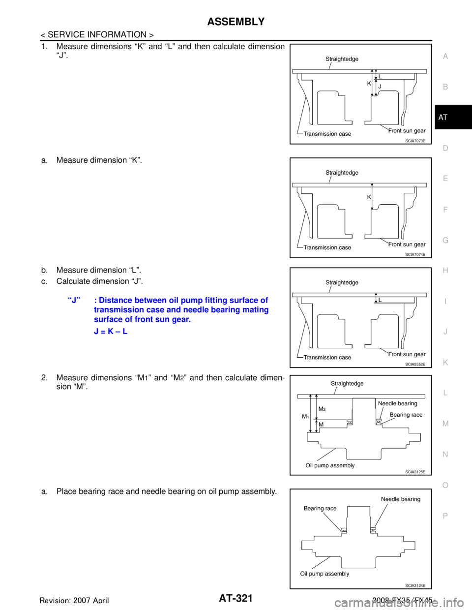
1. Measure dimensions “K” and “L” and then calculate dimension “J”.
a. Measure dimension “K”.
b. Measure dimension “L”.
c. Calculate dimension “J”.
2. Measure dimensions “M
1” and “M2” and then calculate dimen-
sion “M”.
a. Place bearing race and needle bearing on oil pump assembly.
SCIA7073E
SCIA7074E
“J” : Distance between oil pump fitting surface of transmission case and n eedle bearing mating
surface of front sun gear.
J = K – L
SCIA5352E
SCIA3125E
SCIA3124E
3AA93ABC3ACD3AC03ACA3AC03AC63AC53A913A773A893A873A873A8E3A773A983AC73AC93AC03AC3
3A893A873A873A8F3A773A9D3AAF3A8A3A8C3A863A9D3AAF3A8B3A8C
Page 636 of 3924

NAVIGATION SYSTEMAV-89
< SERVICE INFORMATION >
C
DE
F
G H
I
J
L
M A
B
AV
N
O P
In map-matching, alternative routes are prepared and prioritized in addition to the road judged currently driven. Due to the distance
and/or direction error, the incorrect road may be prioritized and
current-location mark may be repositioned to the wrong road.
When two roads are running in parallel, they are judged to the
same priority. Therefore, the current-location mark may appear on
either of them alternately, depending on maneuvering of the steer-
ing wheel and configuration of the road.
Map-matching does not function correctly when a road on which the vehicle is driving is new and not recorded in the DVD-ROM, or
when road pattern stored in the map data and the actual road pat-
tern are different due to repair.
When driving on a road not present in the map, the map-matching
function may find another road and position the current-location
mark on it. Then, when the correc t road is detected, the current-
location mark may change to it.
Effective range for comparing the vehicle position and travel direc-
tion calculated by the distance and direction with the road data
read from the DVD-ROM is limited. Therefore, when there is an
excessive gap between current vehicle position and the position on
the map, correction by map-matching is not possible.
GPS (Global Positioning System)
GPS (Global Positioning System) was developed for and is con-
trolled by the US Department of Defense. The system utilizes GPS
satellites (NAVSTAR), sending out radio waves while flying on an
orbit around the earth at an altitude of approximately 21,000 km
(13,100 miles).
The GPS receiver calculates the vehicle's position in three dimen-
sions (latitude/longitude/altitude) ac cording to the time lag of the
radio waves received from four or more GPS satellites (three-dimen-
sional positioning). If radio waves were received only from three
GPS satellites, the GPS receiver ca lculates the vehicle's position in
two dimensions (latitude/longitude) , and utilize the altitude data cal-
culated previously with radio waves from four or more GPS satellites
(two-dimensional positioning).
Position correction by GPS is not available while the vehicle is stopped.
Accuracy of GPS will deteriorate under the following conditions:
In two-dimensional positioning, GPS accuracy will deter iorate when altitude of the vehicle position changes.
The accuracy can be even lower depending on the arrangement of the GPS satellites utilized for the posi-
tioning.
Position detection is not possible when vehicle is in an area where radio waves from the GPS satellite do not
reach, such as in a tunnel, parking lot in a building, and under an elevated highway. Radio waves from the
GPS satellites may not be received when so me object is located over the GPS antenna.
NOTE:
Even a high-precision three dimensional positioning, the detection result has an error about 10 m (30ft).
Because the signals of GPS satellite is controlled by the Tracking and Control Center in the United States,
the accuracy may be degraded lower intentionally or the radio waves may stop.
Component DescriptionINFOID:0000000001328740
NAVI CONTROL UNIT
SEL686V
SKIA0613E
SEL526V
3AA93ABC3ACD3AC03ACA3AC03AC63AC53A913A773A893A873A873A8E3A773A983AC73AC93AC03AC3
3A893A873A873A8F3A773A9D3AAF3A8A3A8C3A863A9D3AAF3A8B3A8C
Page 951 of 3924

BODY REPAIRBL-217
< SERVICE INFORMATION >
C
DE
F
G H
J
K L
M A
B
BL
N
O P
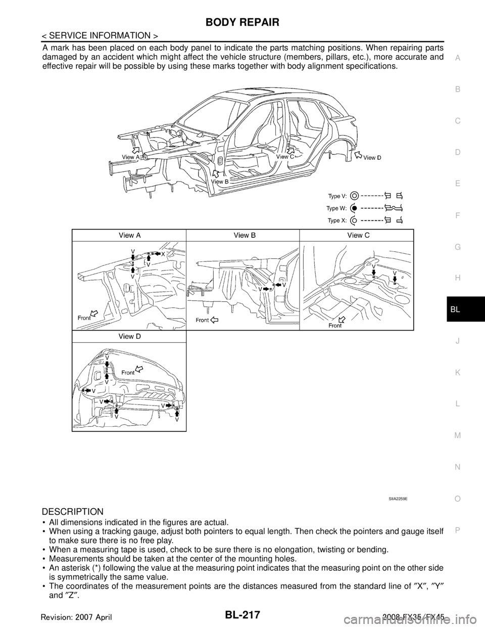
A mark has been placed on each body panel to indicate the parts matching positions. When repairing parts
damaged by an accident which might affect the vehicle stru cture (members, pillars, etc.), more accurate and
effective repair will be possible by using these ma rks together with body alignment specifications.
DESCRIPTION
All dimensions indicated in the figures are actual.
When using a tracking gauge, adjust both pointers to equal length. Then check the pointers and gauge itself
to make sure there is no free play.
When a measuring tape is used, check to be su re there is no elongation, twisting or bending.
Measurements should be taken at the center of the mounting holes.
An asterisk (*) following the value at the measuring poi nt indicates that the measuring point on the other side
is symmetrically the same value.
The coordinates of the measurement points are the distances measured from the standard line of ″X ″, ″Y ″
and ″Z ″.
SIIA2259E
3AA93ABC3ACD3AC03ACA3AC03AC63AC53A913A773A893A873A873A8E3A773A983AC73AC93AC03AC3
3A893A873A873A8F3A773A9D3AAF3A8A3A8C3A863A9D3AAF3A8B3A8C
Page 1075 of 3924
![INFINITI FX35 2008 Service Manual
CO-4
< SERVICE INFORMATION >[VQ35DE]
PRECAUTIONS
3. Attach liquid gasket tube to the tube presser (commercial ser-
vice tool).
Use Genuine RTV Silicone Seal ant or equivalent. Refer to
GI-44, "
Recom INFINITI FX35 2008 Service Manual
CO-4
< SERVICE INFORMATION >[VQ35DE]
PRECAUTIONS
3. Attach liquid gasket tube to the tube presser (commercial ser-
vice tool).
Use Genuine RTV Silicone Seal ant or equivalent. Refer to
GI-44, "
Recom](/img/42/57017/w960_57017-1074.png)
CO-4
< SERVICE INFORMATION >[VQ35DE]
PRECAUTIONS
3. Attach liquid gasket tube to the tube presser (commercial ser-
vice tool).
Use Genuine RTV Silicone Seal ant or equivalent. Refer to
GI-44, "
Recommended Chemical Product and Sealant".
4. Apply liquid gasket without breaks to the specified location with the specified dimensions.
If there is a groove for the liquid gasket application, apply liq-
uid gasket to the groove.
As for the bolt holes, normally apply liquid gasket inside the holes. Occasionally, it should be applied outside the holes.
Make sure to read the text of service manual.
Within five minutes of liquid gasket application, install the mat-
ing component.
If liquid gasket protrudes, wipe it off immediately.
Do not retighten after mounting bolts and nuts the installation.
After 30 minutes or more have passed from the installation, fill engine oil and engine coolant.
CAUTION:
If there are specific instructions in this manual, observe them.
EMA0622D
SEM159F
3AA93ABC3ACD3AC03ACA3AC03AC63AC53A913A773A893A873A873A8E3A773A983AC73AC93AC03AC3
3A893A873A873A8F3A773A9D3AAF3A8A3A8C3A863A9D3AAF3A8B3A8C
Page 1210 of 3924

DI-84
< SERVICE INFORMATION >
LANE DEPARTURE WARNING SYSTEM
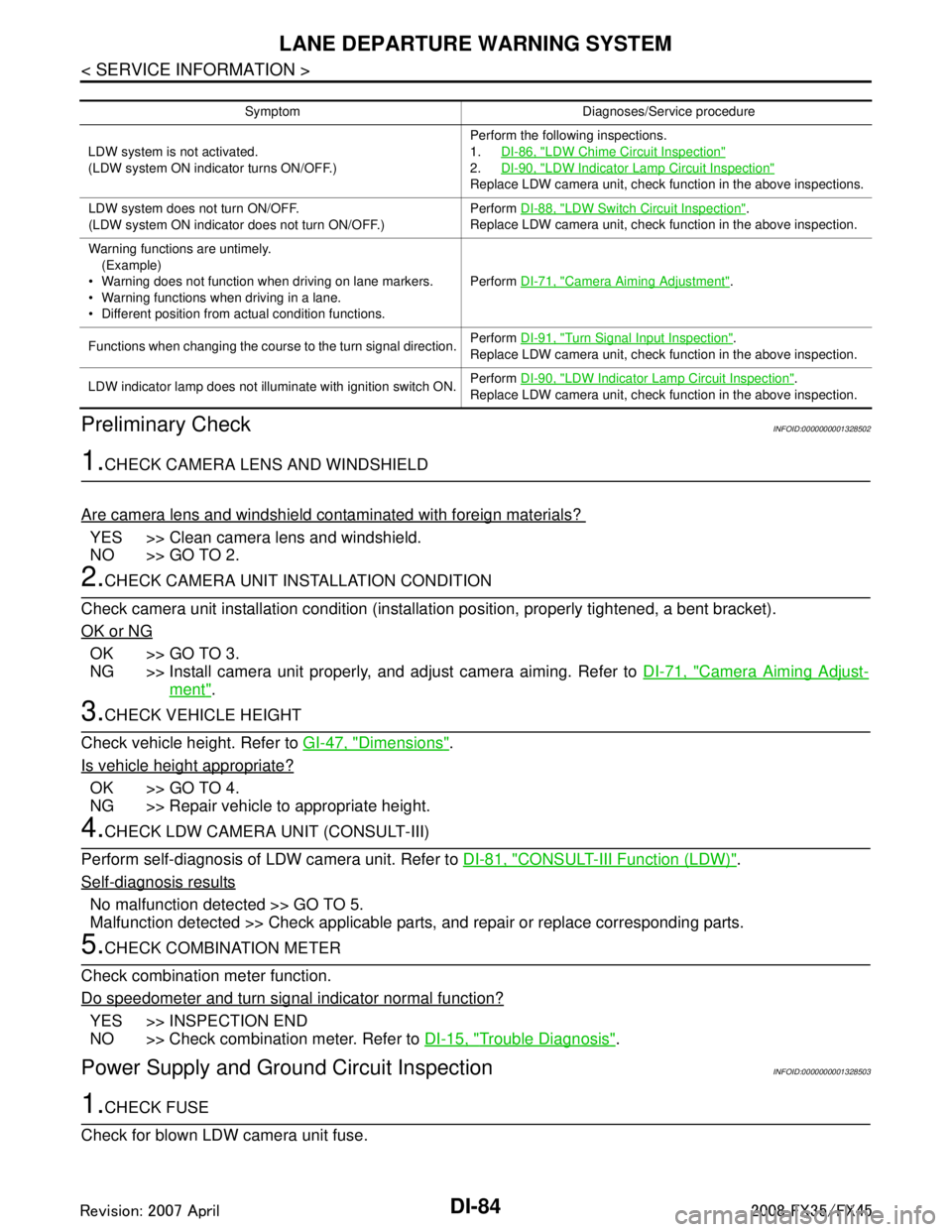
Preliminary Check
INFOID:0000000001328502
1.CHECK CAMERA LENS AND WINDSHIELD
Are camera lens and windshield contaminated with foreign materials?
YES >> Clean camera lens and windshield.
NO >> GO TO 2.
2.CHECK CAMERA UNIT IN STALLATION CONDITION
Check camera unit installation condition (installat ion position, properly tightened, a bent bracket).
OK or NG
OK >> GO TO 3.
NG >> Install camera unit properly, and adjust camera aiming. Refer to DI-71, "
Camera Aiming Adjust-
ment".
3.CHECK VEHICLE HEIGHT
Check vehicle height. Refer to GI-47, "
Dimensions".
Is vehicle height appropriate?
OK >> GO TO 4.
NG >> Repair vehicle to appropriate height.
4.CHECK LDW CAMERA UNIT (CONSULT-III)
Perform self-diagnosis of LDW camera unit. Refer to DI-81, "
CONSULT-III Function (LDW)".
Self
-diagnosis results
No malfunction detected >> GO TO 5.
Malfunction detected >> Check applicable parts, and repair or replace corresponding parts.
5.CHECK COMBINATION METER
Check combination meter function.
Do speedometer and turn signal indicator normal function?
YES >> INSPECTION END
NO >> Check combination meter. Refer to DI-15, "
Trouble Diagnosis".
Power Supply and Ground Circuit InspectionINFOID:0000000001328503
1.CHECK FUSE
Check for blown LDW camera unit fuse.
Symptom Diagnoses/Service procedure
LDW system is not activated.
(LDW system ON indicator turns ON/OFF.) Perform the following inspections.
1.
DI-86, "
LDW Chime Circuit Inspection"
2.DI-90, "LDW Indicator Lamp Circuit Inspection"
Replace LDW camera unit, check function in the above inspections.
LDW system does not turn ON/OFF.
(LDW system ON indicator does not turn ON/OFF.) Perform
DI-88, "
LDW Switch Circuit Inspection".
Replace LDW camera unit, check function in the above inspection.
Warning functions are untimely. (Example)
Warning does not function when driving on lane markers.
Warning functions when driving in a lane.
Different position from actual condition functions. Perform
DI-71, "
Camera Aiming Adjustment".
Functions when changing the course to the turn signal direction. Perform
DI-91, "
Turn Signal Input Inspection".
Replace LDW camera unit, check function in the above inspection.
LDW indicator lamp does not illuminate with ignition switch ON. Perform
DI-90, "
LDW Indicator Lamp Circuit Inspection".
Replace LDW camera unit, check function in the above inspection.
3AA93ABC3ACD3AC03ACA3AC03AC63AC53A913A773A893A873A873A8E3A773A983AC73AC93AC03AC3
3A893A873A873A8F3A773A9D3AAF3A8A3A8C3A863A9D3AAF3A8B3A8C
Page 2490 of 3924
![INFINITI FX35 2008 Service Manual
EM-6
< SERVICE INFORMATION >[VQ35DE]
PRECAUTIONS
3. Attach liquid gasket tube to the tube presser (commercial ser-
vice tool).
Use Genuine RTV Silicone Seal ant or equivalent. Refer to
GI-44
.
4. App INFINITI FX35 2008 Service Manual
EM-6
< SERVICE INFORMATION >[VQ35DE]
PRECAUTIONS
3. Attach liquid gasket tube to the tube presser (commercial ser-
vice tool).
Use Genuine RTV Silicone Seal ant or equivalent. Refer to
GI-44
.
4. App](/img/42/57017/w960_57017-2489.png)
EM-6
< SERVICE INFORMATION >[VQ35DE]
PRECAUTIONS
3. Attach liquid gasket tube to the tube presser (commercial ser-
vice tool).
Use Genuine RTV Silicone Seal ant or equivalent. Refer to
GI-44
.
4. Apply liquid gasket without breaks to the specified location with the specified dimensions.
If there is a groove for liquid gasket application, apply liquid
gasket to the groove.
As for bolt holes, normally apply liquid gasket inside the holes. Occasionally, it should be applied outside the holes. Make
sure to read the text of this manual.
Within five minutes of liquid gasket application, install the mat-
ing component.
If liquid gasket protrudes, wipe it off immediately.
Do not retighten mounting bolts or nuts after the installation.
After 30 minutes or more have passed from the installation, fill engine oil and engine coolant.
CAUTION:
If there are specific instruct ions in this manual, observe
them.
EMA0622D
SEM159F
3AA93ABC3ACD3AC03ACA3AC03AC63AC53A913A773A893A873A873A8E3A773A983AC73AC93AC03AC3
3A893A873A873A8F3A773A9D3AAF3A8A3A8C3A863A9D3AAF3A8B3A8C
Page 2494 of 3924
![INFINITI FX35 2008 Service Manual
EM-10
< SERVICE INFORMATION >[VQ35DE]
PREPARATION
(—)
TORX socketRemoving and installing flywheel
Size: T55
(—)
Manual lift table caddy Removing and installing engine
(J24239-01)
Cylinder head b INFINITI FX35 2008 Service Manual
EM-10
< SERVICE INFORMATION >[VQ35DE]
PREPARATION
(—)
TORX socketRemoving and installing flywheel
Size: T55
(—)
Manual lift table caddy Removing and installing engine
(J24239-01)
Cylinder head b](/img/42/57017/w960_57017-2493.png)
EM-10
< SERVICE INFORMATION >[VQ35DE]
PREPARATION
(—)
TORX socketRemoving and installing flywheel
Size: T55
(—)
Manual lift table caddy Removing and installing engine
(J24239-01)
Cylinder head bolt wrench Loosening and tightening cylinder head bolt,
and used with the angle wrench [SST:
KV10112100 (BT8653-A)]
a: 13 (0.51) dia.
b: 12 (0.47)
c: 10 (0.39)
Unit: mm (in)
(—)
1.Compression tester
2.Adapter Checking compression pressure
(—)
Spark plug wrench Removing and installing spark plug
(—)
Valve seat cutter set Finishing valve seat dimensions
(—)
Piston ring expander Removing and installing piston ring
(Kent-Moore No.)
Tool name
Description
PBIC1113E
ZZA1210D
NT583
ZZA0008D
NT047
NT048
NT030
3AA93ABC3ACD3AC03ACA3AC03AC63AC53A913A773A893A873A873A8E3A773A983AC73AC93AC03AC3
3A893A873A873A8F3A773A9D3AAF3A8A3A8C3A863A9D3AAF3A8B3A8C
Page 2591 of 3924
![INFINITI FX35 2008 Service Manual
CYLINDER HEADEM-107
< SERVICE INFORMATION > [VQ35DE]
C
D
E
F
G H
I
J
K L
M A
EM
NP
O
8. Install valve collet.
Compress valve spring with the valve spring compressor, theattachment and the adapter ( INFINITI FX35 2008 Service Manual
CYLINDER HEADEM-107
< SERVICE INFORMATION > [VQ35DE]
C
D
E
F
G H
I
J
K L
M A
EM
NP
O
8. Install valve collet.
Compress valve spring with the valve spring compressor, theattachment and the adapter (](/img/42/57017/w960_57017-2590.png)
CYLINDER HEADEM-107
< SERVICE INFORMATION > [VQ35DE]
C
D
E
F
G H
I
J
K L
M A
EM
NP
O
8. Install valve collet.
Compress valve spring with the valve spring compressor, theattachment and the adapter (SST). Install valve collet with a
magnet hand.
CAUTION:
When working, take care not to damage valve lifter holes.
Tap valve stem edge lightly with plastic hammer after installa- tion to check its installed condition.
9. Install valve lifter. Install it in the original position.
10. Install spark plug tube. Press-fit spark plug tube as follows:
a. Remove old liquid gasket adhering to cylinder head mounting hole.
b. Apply sealant to area within approximately 12 mm (0.47 in) from edge of spark plug tube press-fit side.
Use Genuine High Strength Locking Sealant or equivalent. Refer to GI-44
.
c. Using drift, press-fit spark plug tube so that its height “H” is as specified in the figure.
CAUTION:
When press-fitting, take care not to deform spark plugtube.
After press-fitting, wipe o ff liquid gasket protruding onto
cylinder-head upper face.
11. Install spark plug with spark plug wrench (commercial service tool).
Inspection After DisassemblyINFOID:0000000001325741
VALVE DIMENSIONS
Check the dimensions of each valv e. For the dimensions, refer to EM-149, "Standard and Limit".
If dimensions are out of the standard, replace valve and check valve seat contact. Refer to "VALVE SEAT
CONTACT".
VALVE GUIDE CLEARANCE
Valve Stem Diameter
Measure the diameter of va lve stem with micrometer.
Valve Guide Inner Diameter
Measure the inner diameter of valve guide with an inside micrometer.
PBIC1803E
Standard press-fit height “H”:
: 38.1 - 39.1 mm (1.500 - 1.539 in)
PBIC2638E
StandardIntake : 5.965 - 5.980 mm (0.2348 - 0.2354 in)
Exhaust : 5.955 - 5.970 mm (0.2344 - 0.2350 in)
SEM938C
3AA93ABC3ACD3AC03ACA3AC03AC63AC53A913A773A893A873A873A8E3A773A983AC73AC93AC03AC3
3A893A873A873A8F3A773A9D3AAF3A8A3A8C3A863A9D3AAF3A8B3A8C
Page 2593 of 3924
![INFINITI FX35 2008 Service Manual
CYLINDER HEADEM-109
< SERVICE INFORMATION > [VQ35DE]
C
D
E
F
G H
I
J
K L
M A
EM
NP
O
4. Heat cylinder head to 110 to 130
°C (230 to 266 °F) by soaking in
heated oil.
5. Using the valve guide drift INFINITI FX35 2008 Service Manual
CYLINDER HEADEM-109
< SERVICE INFORMATION > [VQ35DE]
C
D
E
F
G H
I
J
K L
M A
EM
NP
O
4. Heat cylinder head to 110 to 130
°C (230 to 266 °F) by soaking in
heated oil.
5. Using the valve guide drift](/img/42/57017/w960_57017-2592.png)
CYLINDER HEADEM-109
< SERVICE INFORMATION > [VQ35DE]
C
D
E
F
G H
I
J
K L
M A
EM
NP
O
4. Heat cylinder head to 110 to 130
°C (230 to 266 °F) by soaking in
heated oil.
5. Using the valve guide drift (commercial service tool), press valve guide from camshaft side to the dimensions as in the figure.
WARNING:
Cylinder head contains heat . When working, wear protec-
tive equipment to avo id getting burned.
6. Using the valve guide reamer (commercial service tool), apply reamer finish to valve guide.
VALVE SEAT CONTACT
After confirming that the dimensions of valve guides and valves arewithin the specifications, perform this procedure.
Apply prussian blue (or white lead) onto contacting surface of valve seat to check the condition of the valve contact on the surface.
Check if the contact area band is continuous all around the circum-
ference.
If not, grind to adjust valve fitting and check again. If the contacting surface still has “NG” conditions even after the re-check, replace
valve seat. Refer to "VALVE SEAT REPLACEMENT".
VALVE SEAT REPLACEMENT
When valve seat is removed, replace with oversized [0.5 mm (0.020 in)] valve seat.
1. Bore out old seat until it collapses. Boring shoul d not continue beyond the bottom face of the seat recess
in cylinder head. Set the machine depth stop to ensure this. Refer to EM-149, "
Standard and Limit".
CAUTION:
Prevent to scratch cylinder head by excessive boring.
SEM008A
Projection “L”
Intake and exhaust : 12.6 - 12.8 mm (0.496 - 0.504 in)
SEM950E
Standard:Intake and exhaust : 6.000 - 6.018 mm (0.2362 - 0.2369 in)
SEM932C
SBIA0322E
3AA93ABC3ACD3AC03ACA3AC03AC63AC53A913A773A893A873A873A8E3A773A983AC73AC93AC03AC3
3A893A873A873A8F3A773A9D3AAF3A8A3A8C3A863A9D3AAF3A8B3A8C
Page 2594 of 3924
![INFINITI FX35 2008 Service Manual
EM-110
< SERVICE INFORMATION >[VQ35DE]
CYLINDER HEAD
2. Ream cylinder head recess diameter for service valve seat.
Be sure to ream in circles concentric to valve guide center.This will enable valve INFINITI FX35 2008 Service Manual
EM-110
< SERVICE INFORMATION >[VQ35DE]
CYLINDER HEAD
2. Ream cylinder head recess diameter for service valve seat.
Be sure to ream in circles concentric to valve guide center.This will enable valve](/img/42/57017/w960_57017-2593.png)
EM-110
< SERVICE INFORMATION >[VQ35DE]
CYLINDER HEAD
2. Ream cylinder head recess diameter for service valve seat.
Be sure to ream in circles concentric to valve guide center.This will enable valve to fit correctly.
3. Heat cylinder head to 110 to 130 °C (230 to 266 °F) by soaking in
heated oil.
4. Provide valve seats cooled well with dry ice. Force fit valve seat into cylinder head. WARNING:
Cylinder head contains heat. When working, wear protecti ve equipment to avoid getting burned.
CAUTION:
Avoid directly touching cold valve seats.
5. Using the valve seat cutter set (commercial service tool) or valve
seat grinder, finish seat to the specified dimensions. Refer to
EM-149, "
Standard and Limit".
CAUTION:
When using the valve seat cutter, firmly grip cutter handle
with both hands. Then, pr ess on the contacting surface all
around the circumference to cu t in a single drive. Improper
pressure on with cutter or cutting many different times may
result in stage valve seat.
6. Using compound, grind to adjust valve fitting.
7. Check again for normal contact. Refer to "VALVE SEAT CONTACT".
VALVE SPRING SQUARENESS
Set a try square along the side of valve spring and rotate spring. Measure the maximum clearance between the top of spring and try
square.
If it exceeds the limit, replace valve spring.
VALVE SPRING DIMENSIONS AND VALVE SPRING PRESSURE LOAD
Oversize [0.5 mm (0.020 in)] Intake : 38.500 - 38.516 mm (1.5157 - 1.5164 in)
Exhaust : 32.700 - 32.716 mm (1.2874 - 1.2880 in)
SEM795A
SEM008A
SEM934C
Limit : 2.1 mm (0.083 in)
PBIC0080E
3AA93ABC3ACD3AC03ACA3AC03AC63AC53A913A773A893A873A873A8E3A773A983AC73AC93AC03AC3
3A893A873A873A8F3A773A9D3AAF3A8A3A8C3A863A9D3AAF3A8B3A8C