warning INFINITI FX35 2008 Service Manual
[x] Cancel search | Manufacturer: INFINITI, Model Year: 2008, Model line: FX35, Model: INFINITI FX35 2008Pages: 3924, PDF Size: 81.37 MB
Page 3816 of 3924

TF-30
< SERVICE INFORMATION >
TROUBLE DIAGNOSIS FOR SYMPTOMS
TROUBLE DIAGNOSIS FOR SYMPTOMS
AWD Warning Lamp Does Not Turn ON When the Ignition Switch Is Turned to ON
INFOID:0000000001327450
DIAGNOSTIC PROCEDURE
1.CHECK SYSTEM FOR CAN COMMUNICATION LINE
Perform self-diagnosis. Refer to TF-21, "
CONSULT-III Function (ALL MODE AWD/4WD)".
Is the
“CAN COMM CIRCUIT [U1000]” displayed?
YES >> Perform trouble diagnosis for CAN communication line. Refer to TF-28, "DTC U1000 CAN COMM
CIRCUIT".
NO >> GO TO 2.
2.CHECK AWD CONTROL UNIT
Check AWD control unit input/output signal. Refer to TF-20, "
AWD Control Unit Input/Output Signal Reference
Va l u e".
OK or NG
OK >> GO TO 3.
NG >> Check AWD control unit pin terminals for dam age or loose connection with harness connector. If
any items are damaged, repair or replace damaged parts.
3.CHECK OUTPUT SIGNAL WITH UNIFIED METER AND A/C AMP.
With CONSULT-III
1. Turn ignition switch “ON”. (Do not start engine.)
2. Select “DATA MONITOR” mode for “METER A/C AMP” with CONSULT-III.
3. Start the engine, and then make sure that “4WD W/L” display turns from “ON” to “OFF” after several sec-
onds.
OK or NG
OK >> GO TO 4.
NG >> Perform trouble diagnosis for combination meter. Refer to DI-15, "
Trouble Diagnosis".
4.SYMPTOM CHECK
Check again.
OK or NG
OK >> INSPECTION END
NG >> Replace unified meter control unit assembly. Refer to DI-23, "
Disassembly and Assembly of Com-
bination Meter".
AWD Warning Lamp Does Not Turn OFF Several Seconds after Engine Started
INFOID:0000000001327451
DIAGNOSTIC PROCEDURE
1.CHECK SELF-DIAGNOSTIC RESULTS
Perform self-diagnosis. Refer to TF-21, "
CONSULT-III Function (ALL MODE AWD/4WD)".
Is any malfunction detec ted by self-diagnosis?
YES >> Check the malfunctioning system.
NO >> GO TO 2.
2.CHECK AWD CONTROL UNIT POWER SUPPLY CIRCUIT
1. Turn ignition switch “OFF”.
Monitor item Condition Display value
4WD W/L Ignition switch ON ON
Start engine (after several seconds) OFF
3AA93ABC3ACD3AC03ACA3AC03AC63AC53A913A773A893A873A873A8E3A773A983AC73AC93AC03AC3
3A893A873A873A8F3A773A9D3AAF3A8A3A8C3A863A9D3AAF3A8B3A8C
Page 3819 of 3924
TROUBLE DIAGNOSIS FOR SYMPTOMSTF-33
< SERVICE INFORMATION >
CEF
G H
I
J
K L
M A
B
TF
N
O P
5.SYMPTOM CHECK
Check again.
OK or NG
OK >> INSPECTION END
NG >> GO TO 6.
6.CHECK AWD CONTROL UNIT
Check AWD control unit input/output signal. Refer to TF-20, "
AWD Control Unit Input/Output Signal Reference
Va l u e".
OK or NG
OK >> INSPECTION END
NG >> Check AWD control unit pin terminals for damage or loose connection with harness connector. If any items are damaged, repair or replace damaged parts.
Vehicle Does Not Enter AW D Mode Even Though AWD Warn ing Lamp Turned to OFF
INFOID:0000000001327453
DIAGNOSTIC PROCEDURE
1.CHECK AWD SOLENOID
Check AWD solenoid. Refer to TF-25, "
DTC C1204 4WD SOLENOID".
OK or NG
OK >> GO TO 2.
NG >> Replace electric controlled coupling for malfunction of AWD solenoid. Refer to TF-40, "
Disassem-
bly and Assembly".
2.CHECK AWD CONTROL UNIT
Check AWD control unit input/output signal. Refer to TF-20, "
AWD Control Unit Input/Output Signal Reference
Va l u e".
OK or NG
OK >> GO TO 3.
NG >> Check AWD control unit pin terminals for damage or loose connection with harness connector. If any items are damaged, repair or replace damaged parts.
3.SYMPTOM CHECK
Check again.
OK or NG
OK >> INSPECTION END
NG >> Replace electric controlled coupling fo r mechanical malfunction (mechanical engagement of
clutch is not possible.). Refer to TF-40, "
Disassembly and Assembly".
While Driving, AWD Warning Lamp Flashes Rapidly (When Flashing in Approx. 1
Minute and Then Turning OFF)
INFOID:0000000001327454
NOTE:
Rapid flashing: 2 times/second
This symptom protects drivetrain parts when a heavy load is applied to the electric controlled coupling and
multiple disc clutch temperature increases. Also, opt ional distribution of torque sometimes becomes rigid
before lamp flashes rapidly. Both cases are not malfunction.
When this symptom occurs, stop vehicle and allow it to idle for some times. Flashing will stop and system will
be restored.
While Driving, AWD Warning Lamp Flashes Slowly (When Continuing to Flash until
Turning Ignition Switch OFF)
INFOID:0000000001327455
NOTE:
Slow flashing: 1 time/2 seconds
3AA93ABC3ACD3AC03ACA3AC03AC63AC53A913A773A893A873A873A8E3A773A983AC73AC93AC03AC3
3A893A873A873A8F3A773A9D3AAF3A8A3A8C3A863A9D3AAF3A8B3A8C
Page 3841 of 3924

WT-1
SUSPENSION
C
DF
G H
I
J
K L
M
SECTION WT
A
B
WT
N
O PCONTENTS
ROAD WHEELS & TIRES
SERVICE INFORMATION .. ..........................2
INDEX FOR DTC ............................................ .....2
DTC No. Index .................................................... ......2
PRECAUTIONS ...................................................3
Precaution for Supplemental Restraint System
(SRS) "AIR BAG" and "SEAT BELT PRE-TEN-
SIONER" ............................................................. ......
3
Precaution .................................................................3
Service Notice or Precaution .....................................4
PREPARATION ...................................................5
Special Service Tool ........................................... ......5
Commercial Service Tool ..........................................5
NOISE, VIBRATION AND HARSHNESS
(NVH) TROUBLESHOOTING .............................
6
NVH Troubleshooting Chart ................................ ......6
ROAD WHEEL ....................................................7
Inspection ............................................................ ......7
ROAD WHEEL TIRE ASSEMBLY ......................8
Balancing Wheels (Bonding Weight Type) .......... ......8
Tire Rotation ..............................................................9
TIRE PRESSURE MONITORING SYSTEM .......10
System Component ............................................. ....10
System Description .................................................10
CAN COMMUNICATION ....................................13
System Description ............................................. ....13
TROUBLE DIAGNOSES ....................................14
Schematic ........................................................... ....14
Wiring Diagram- T/WARN - .....................................15
Control Unit Input/Output Signal Standard ..............17
ID Registration Procedure ................................... ....19
Transmitter Wake Up Operation ..............................20
Self-Diagnosis .........................................................20
CONSULT-III Function (BCM) .................................22
How to Perform Trouble Diagnosis for Quick and
Accurate Repair .......................................................
24
Preliminary Check ...................................................25
Malfunction Code/Symptom Chart ...........................26
TROUBLE DIAGNOSIS FOR SELF-DIAG-
NOSTIC ITEMS .................................................
28
Transmitter or Control Unit (BCM) ...........................28
Transmitter - 1 .........................................................28
Transmitter - 2 .........................................................29
Vehicle Speed Signal ..............................................29
TROUBLE DIAGNOSIS FOR SYMPTOMS ......30
Low Tire Pressure Warning Lamp Does Not Come
On When Ignition Switch Is Turned On ...................
30
Low Tire Pressure Warning Lamp Stays On When
Ignition Switch Is Turned On ............................... ....
30
Low Tire Pressure Warning Lamp Blinks When Ig-
nition Switch Is Turned On ......................................
31
Run-Flat Tire Warning Lamp Stays On When Igni-
tion Switch Is Turned On .........................................
32
Turn Signal Lamp Blinks When Ignition Switch Is
Turned On ...............................................................
32
ID Registration Cannot Be Completed ....................32
REMOVAL AND INSTALLATION .....................33
Transmitter ..............................................................33
SERVICE DATA AND SPECIFICATIONS
(SDS) .................................................................
35
Road Wheel .............................................................35
Tire ..........................................................................35
3AA93ABC3ACD3AC03ACA3AC03AC63AC53A913A773A893A873A873A8E3A773A983AC73AC93AC03AC3
3A893A873A873A8F3A773A9D3AAF3A8A3A8C3A863A9D3AAF3A8B3A8C
Page 3843 of 3924

PRECAUTIONSWT-3
< SERVICE INFORMATION >
C
DF
G H
I
J
K L
M A
B
WT
N
O P
PRECAUTIONS
Precaution for Supplemental Restraint System (SRS) "AIR BAG" and "SEAT BELT
PRE-TENSIONER"
INFOID:0000000001612926
The Supplemental Restraint System such as “A IR BAG” and “SEAT BELT PRE-TENSIONER”, used along
with a front seat belt, helps to reduce the risk or severi ty of injury to the driver and front passenger for certain
types of collision. This system includes seat belt switch inputs and dual stage front air bag modules. The SRS
system uses the seat belt switches to determine the front air bag deployment, and may only deploy one front
air bag, depending on the severity of a collision and whether the front occupants are belted or unbelted.
Information necessary to service the system safely is included in the “SUPPLEMENTAL RESTRAINT SYS-
TEM” and “SEAT BELTS” of this Service Manual.
WARNING:
• To avoid rendering the SRS inoper ative, which could increase the risk of personal injury or death in
the event of a collision which would result in air bag inflation, all maintenance must be performed by
an authorized NISSAN/INFINITI dealer.
Improper maintenance, including in correct removal and installation of the SRS, can lead to personal
injury caused by unintentional act ivation of the system. For removal of Spiral Cable and Air Bag
Module, see the “SUPPLEMEN TAL RESTRAINT SYSTEM”.
Do not use electrical test equipm ent on any circuit related to the SRS unless instructed to in this
Service Manual. SRS wiring harnesses can be identi fied by yellow and/or orange harnesses or har-
ness connectors.
PrecautionINFOID:0000000001327568
Before connecting or disco nnecting the BCM harness con-
nector, turn ignition switch “OFF” and disconnect the battery
cable from the negative terminal. Battery voltage is applied to
BCM even if ignition sw itch is turned “OFF”.
When connecting or disconnect ing pin connectors into or
from BCM, take care not to damage pin terminals (bend or
break).
When connecting pin connectors make sure that there are not
any bends or breaks on BCM pin terminals.
SEF289H
SEF291H
3AA93ABC3ACD3AC03ACA3AC03AC63AC53A913A773A893A873A873A8E3A773A983AC73AC93AC03AC3
3A893A873A873A8F3A773A9D3AAF3A8A3A8C3A863A9D3AAF3A8B3A8C
Page 3844 of 3924
WT-4
< SERVICE INFORMATION >
PRECAUTIONS
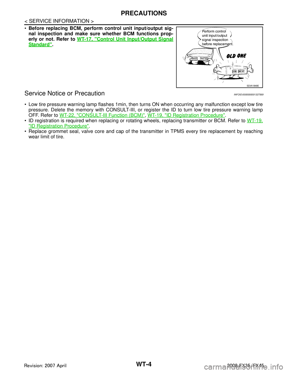
Before replacing BCM, perform c ontrol unit input/output sig-
nal inspection and make sure whether BCM functions prop-
erly or not. Refer to WT-17, "
Control Unit Input/Output Signal
Standard".
Service Notice or PrecautionINFOID:0000000001327569
Low tire pressure warning lamp flashes 1min, then turns ON when occurring any malfunction except low tire
pressure. Delete the memory with CONSULT-III, or regi ster the ID to turn low tire pressure warning lamp
OFF. Refer to WT-22, "
CONSULT-III Function (BCM)", WT-19, "ID Registration Procedure".
ID registration is required when replacing or rotati ng wheels, replacing transmitter or BCM. Refer to WT-19,
"ID Registration Procedure".
Replace grommet seal, valve core and cap of the transmi tter in TPMS every tire replacement by reaching
wear limit of tire.
SDIA1848E
3AA93ABC3ACD3AC03ACA3AC03AC63AC53A913A773A893A873A873A8E3A773A983AC73AC93AC03AC3
3A893A873A873A8F3A773A9D3AAF3A8A3A8C3A863A9D3AAF3A8B3A8C
Page 3851 of 3924
TIRE PRESSURE MONITORING SYSTEMWT-11
< SERVICE INFORMATION >
C
DF
G H
I
J
K L
M A
B
WT
N
O P
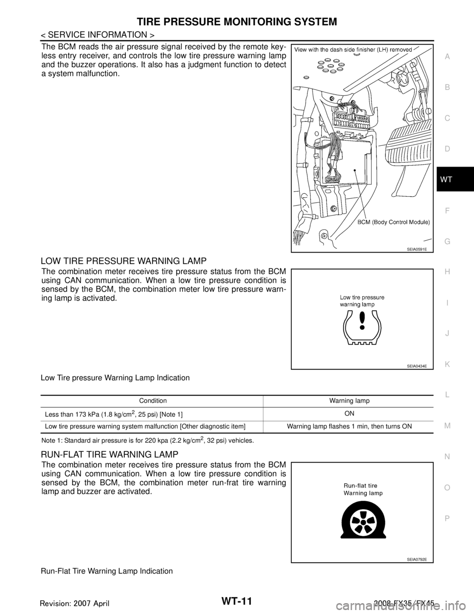
The BCM reads the air pressure signal received by the remote key-
less entry receiver, and controls the low tire pressure warning lamp
and the buzzer operations. It also has a judgment function to detect
a system malfunction.
LOW TIRE PRESSURE WARNING LAMP
The combination meter receives tire pressure status from the BCM
using CAN communication. When a low tire pressure condition is
sensed by the BCM, the combination meter low tire pressure warn-
ing lamp is activated.
Low Tire pressure Warning Lamp Indication
Note 1: Standard air pressure is for 220 kpa (2.2 kg/cm2, 32 psi) vehicles.
RUN-FLAT TIRE WARNING LAMP
The combination meter receives tire pressure status from the BCM
using CAN communication. When a low tire pressure condition is
sensed by the BCM, the combination meter run-frat tire warning
lamp and buzzer are activated.
Run-Flat Tire Warning Lamp Indication
SEIA0591E
SEIA0434E
Condition Warning lamp
Less than 173 kPa (1.8 kg/cm
2, 25 psi) [Note 1] ON
Low tire pressure warning system malfunction [Other diagnostic item] Warning lamp flashes 1 min, then turns ON
SEIA0792E
3AA93ABC3ACD3AC03ACA3AC03AC63AC53A913A773A893A873A873A8E3A773A983AC73AC93AC03AC3
3A893A873A873A8F3A773A9D3AAF3A8A3A8C3A863A9D3AAF3A8B3A8C
Page 3852 of 3924
WT-12
< SERVICE INFORMATION >
TIRE PRESSURE MONITORING SYSTEM
Note 1: Standard air pressure is for 220 kpa (2.2 kg/cm2, 32 psi) vehicles.
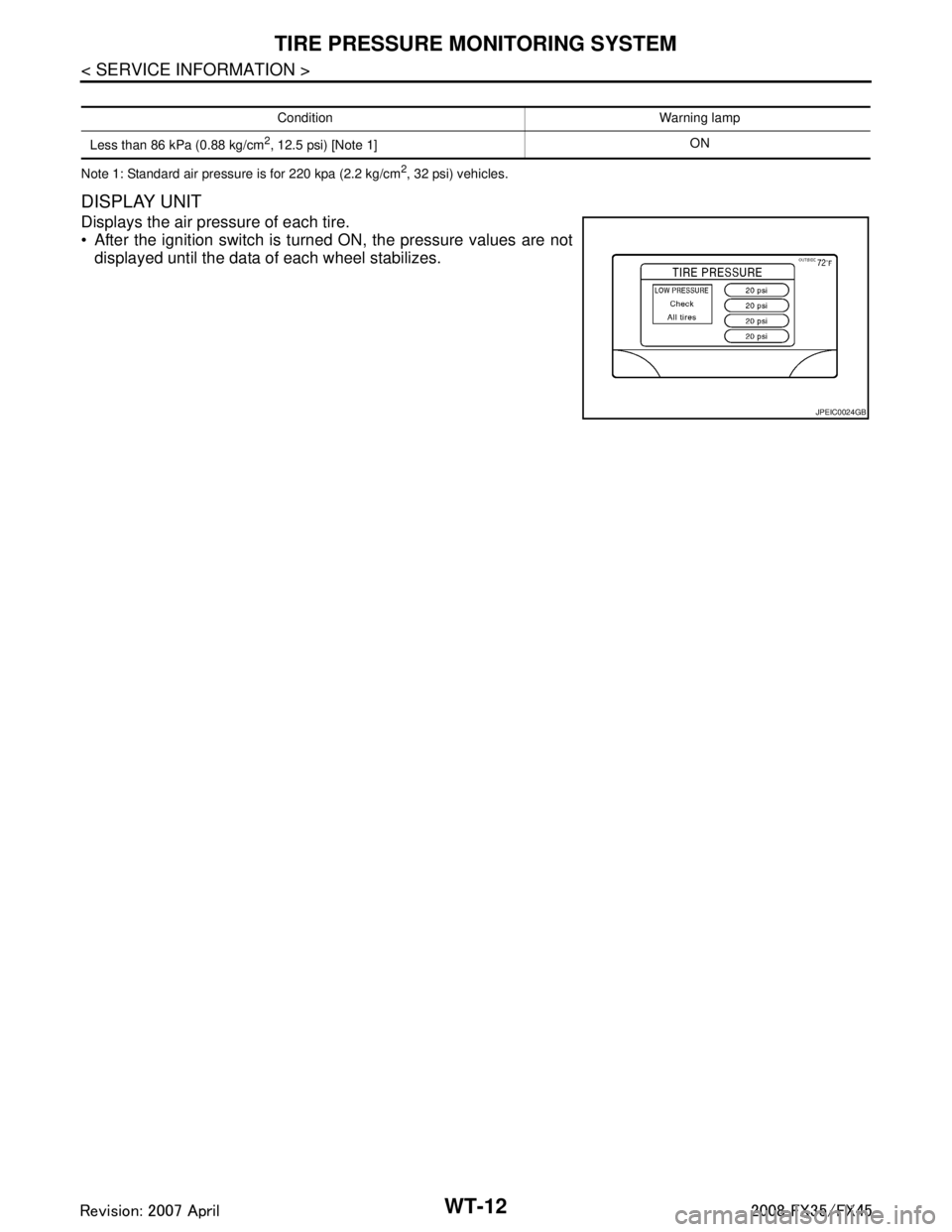
DISPLAY UNIT
Displays the air pressure of each tire.
After the ignition switch is turned ON, the pressure values are notdisplayed until the data of each wheel stabilizes.
Condition Warning lamp
Less than 86 kPa (0.88 kg/cm
2, 12.5 psi) [Note 1] ON
JPEIC0024GB
3AA93ABC3ACD3AC03ACA3AC03AC63AC53A913A773A893A873A873A8E3A773A983AC73AC93AC03AC3
3A893A873A873A8F3A773A9D3AAF3A8A3A8C3A863A9D3AAF3A8B3A8C
Page 3858 of 3924

WT-18
< SERVICE INFORMATION >
TROUBLE DIAGNOSES
Te r m i n a lItem Condition Voltage (V)
Approx. value
+ (wire color) –
15 (G)
Ground Tire pressure
warning check
connector Always 5V
18 (B) Remote keyless entry receiver
(Ground) —0V
19 (R) Remote keyless entry receiver
(Power supply) Stand-by
Press any of the keyfob switch-
es
20 (Y) Remote keyless entry receiver
(Signal) Stand-by
Press any of the keyfob switch-
es
38 (W/L) Ignition switch Ignition switch ON or START Battery voltage (12V) 39 (L) CAN-H — —
40 (P) CAN-L — —
42 (L/R) Battery power supply (Fuse) Always Battery voltage (12V)
45 (G/W) Turn signal (left) Ignition switch ON
Combination switch is turn
signal (left)
OCC3879D
OCC3882D
OCC3881D
OCC3880D
SKIA3009J
3AA93ABC3ACD3AC03ACA3AC03AC63AC53A913A773A893A873A873A8E3A773A983AC73AC93AC03AC3
3A893A873A873A8F3A773A9D3AAF3A8A3A8C3A863A9D3AAF3A8B3A8C
Page 3860 of 3924

WT-20
< SERVICE INFORMATION >
TROUBLE DIAGNOSES
4. Inflate all tires to proper pressure. Refer to WT-35, "Tire".
Transmitter Wake Up OperationINFOID:0000000001327583
W I T H A C T I VAT I O N T O O L
1. With the transmitter activation tool (J-45295) pushed against the
front-left transmitter, press the button for 5 seconds.
When ignition switch ON, as the low tire pressure warninglamp blinks per the following diagram, the respective transmit-
ter then must be woken up.
2. Register the ID of wheel that low tire pressure warning lamp flashes. When wake up of registered wheel
has been completed, turn signal lamp flashes two times.
3. After completing wake up all transmitters, make sure low tire pressure warning lamp goes out.
Self-DiagnosisINFOID:0000000001327584
DESCRIPTION
During driving, the low tire pressure warning syste m receives the signal transmitted from the transmitter
installed in each wheel, and gives alarms when the tire pressure becomes low. The control unit (BCM) of this
system has pressure judgment and trouble diagnosis functions.
FUNCTION
When the low tire pressure warning system detects low inflation pressure or another unusual symptom, the
warning lamps in the combination meter comes on. To start the self-diagnostic results mode, ground terminal
of the tire pressure warning check connector. The malf unction location is indicated by the warning lamp flash-
ing and the buzzer sounds.
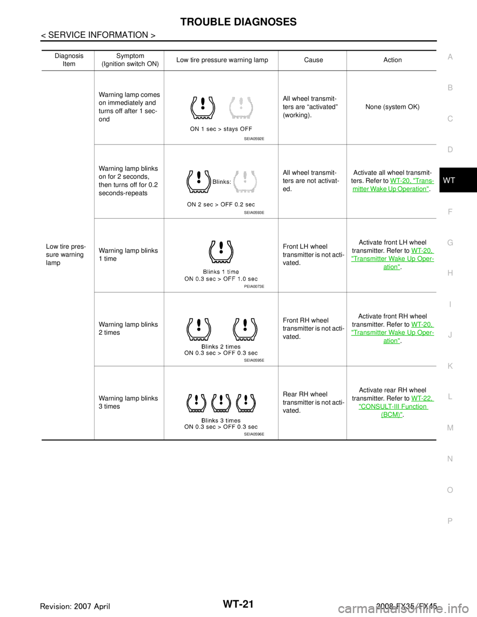
LOW TIRE PRESSURE WARNING LAMP DIAGNOSTIC CHART
Activation tire position CONSULT-III
Front LH “Red”↓
“Green”
Front RH
Rear RHRear LH
SEIA0460E
SEIA0794E
3AA93ABC3ACD3AC03ACA3AC03AC63AC53A913A773A893A873A873A8E3A773A983AC73AC93AC03AC3
3A893A873A873A8F3A773A9D3AAF3A8A3A8C3A863A9D3AAF3A8B3A8C
Page 3861 of 3924
TROUBLE DIAGNOSESWT-21
< SERVICE INFORMATION >
C
DF
G H
I
J
K L
M A
B
WT
N
O P
Diagnosis Item Symptom
(Ignition switch ON) Low tire pressure wa
rning lamp Cause Action
Low tire pres-
sure warning
lamp Warning lamp comes
on immediately and
turns off after 1 sec-
ond
All wheel transmit-
ters are “activated”
(working).
None (system OK)
Warning lamp blinks
on for 2 seconds,
then turns off for 0.2
seconds-repeats All wheel transmit-
ters are not activat-
ed.
Activate all wheel transmit-
ters. Refer to WT-20, "
Trans-
mitter Wake Up Operation".
Warning lamp blinks
1 time Front LH wheel
transmitter is not acti-
vated.Activate front LH wheel
transmitter. Refer to WT-20,
"Transmitter Wake Up Oper-
ation".
Warning lamp blinks
2 times Front RH wheel
transmitter is not acti-
vated.Activate front RH wheel
transmitter. Refer to WT-20,
"Transmitter Wake Up Oper-
ation".
Warning lamp blinks
3 times Rear RH wheel
transmitter is not acti-
vated.Activate rear RH wheel
transmitter. Refer to WT-22,
"CONSULT-III Function
(BCM)".
SEIA0592E
SEIA0593E
PEIA0073E
SEIA0595E
SEIA0596E
3AA93ABC3ACD3AC03ACA3AC03AC63AC53A913A773A893A873A873A8E3A773A983AC73AC93AC03AC3
3A893A873A873A8F3A773A9D3AAF3A8A3A8C3A863A9D3AAF3A8B3A8C