display INFINITI FX35 2008 Service Manual
[x] Cancel search | Manufacturer: INFINITI, Model Year: 2008, Model line: FX35, Model: INFINITI FX35 2008Pages: 3924, PDF Size: 81.37 MB
Page 3263 of 3924

INTERIOR ROOM LAMPLT-161
< SERVICE INFORMATION >
C
DE
F
G H
I
J
L
M A
B
LT
N
O P
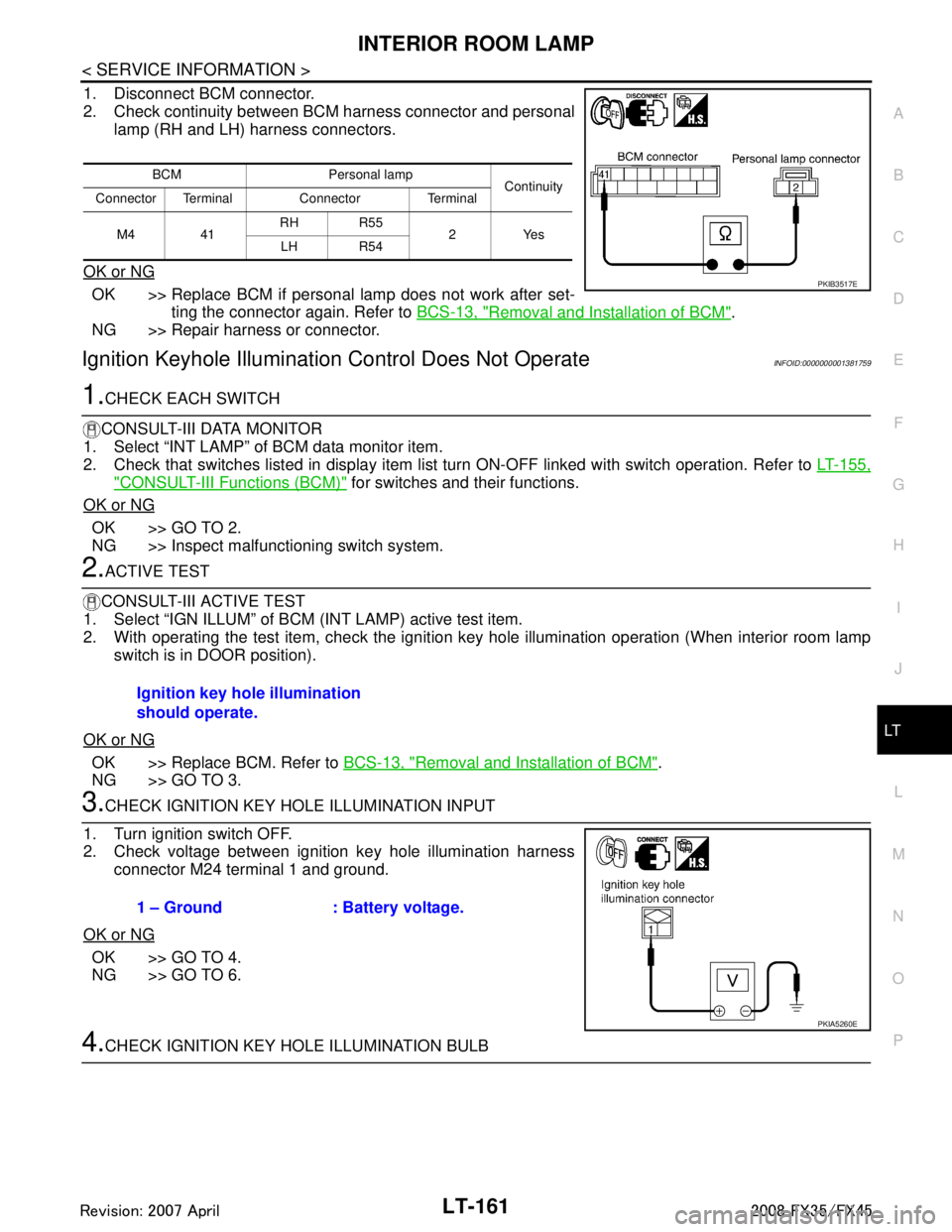
1. Disconnect BCM connector.
2. Check continuity between BCM harness connector and personal lamp (RH and LH) harness connectors.
OK or NG
OK >> Replace BCM if personal lamp does not work after set- ting the connector again. Refer to BCS-13, "
Removal and Installation of BCM".
NG >> Repair harness or connector.
Ignition Keyhole Illumination Control Does Not OperateINFOID:0000000001381759
1.CHECK EACH SWITCH
CONSULT-III DATA MONITOR
1. Select “INT LAMP” of BCM data monitor item.
2. Check that switches listed in display item list turn ON-OFF linked with switch operation. Refer to LT-155,
"CONSULT-III Functions (BCM)" for switches and their functions.
OK or NG
OK >> GO TO 2.
NG >> Inspect malfunctioning switch system.
2.ACTIVE TEST
CONSULT-III ACTIVE TEST
1. Select “IGN ILLUM” of BCM (INT LAMP) active test item.
2. With operating the test item, check the ignition ke y hole illumination operation (When interior room lamp
switch is in DOOR position).
OK or NG
OK >> Replace BCM. Refer to BCS-13, "Removal and Installation of BCM".
NG >> GO TO 3.
3.CHECK IGNITION KEY HOLE ILLUMINATION INPUT
1. Turn ignition switch OFF.
2. Check voltage between ignition key hole illumination harness connector M24 terminal 1 and ground.
OK or NG
OK >> GO TO 4.
NG >> GO TO 6.
4.CHECK IGNITION KEY HOLE ILLUMINATION BULB
BCM Personal lamp Continuity
Connector Terminal Connector Terminal
M4 41 RH R55
2Yes
LH R54
PKIB3517E
Ignition key hole illumination
should operate.
1 – Ground : Battery voltage.
PKIA5260E
3AA93ABC3ACD3AC03ACA3AC03AC63AC53A913A773A893A873A873A8E3A773A983AC73AC93AC03AC3
3A893A873A873A8F3A773A9D3AAF3A8A3A8C3A863A9D3AAF3A8B3A8C
Page 3264 of 3924

LT-162
< SERVICE INFORMATION >
INTERIOR ROOM LAMP
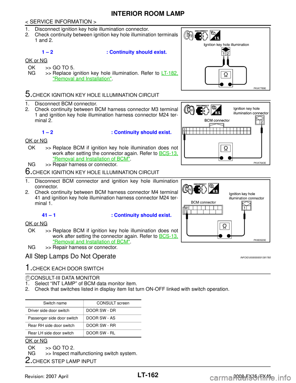
1. Disconnect ignition key hole illumination connector.
2. Check continuity between ignition key hole illumination terminals1 and 2.
OK or NG
OK >> GO TO 5.
NG >> Replace ignition key hole illumination. Refer to LT-182,
"Removal and Installation".
5.CHECK IGNITION KEY HOLE ILLUMINATION CIRCUIT
1. Disconnect BCM connector.
2. Check continuity between BCM harness connector M3 terminal 1 and ignition key hole illumination harness connector M24 ter-
minal 2.
OK or NG
OK >> Replace BCM if ignition key hole illumination does not work after setting the connector again. Refer to BCS-13,
"Removal and Installation of BCM".
NG >> Repair harness or connector.
6.CHECK IGNITION KEY HOLE ILLUMINATION CIRCUIT
1. Disconnect BCM connector and ignition key hole illumination connector.
2. Check continuity between BCM harness connector M4 terminal
41 and ignition key hole illumination harness connector M24 ter-
minal 1.
OK or NG
OK >> Replace BCM if ignition key hole illumination does not work after setting the connector again. Refer to BCS-13,
"Removal and Installation of BCM".
NG >> Repair harness or connector.
All Step Lamps Do Not OperateINFOID:0000000001381760
1.CHECK EACH DOOR SWITCH
CONSULT-III DATA MONITOR
1. Select “INT LAMP” of BCM data monitor item.
2. Check that switches listed in display item list turn ON-OFF linked with switch operation.
OK or NG
OK >> GO TO 2.
NG >> Inspect malfunctioning switch system.
2.CHECK STEP LAMP INPUT 1 – 2 : Continuity should exist.
PKIA7789E
1 – 2 : Continuity should exist.
PKIA7643E
41 – 1 : Continuity should exist.
PKIB3520E
Switch name CONSULT screen
Driver side door switch DOOR SW - DR
Passenger side door switch DOOR SW - AS
Rear RH side door switch DOOR SW - RR
Rear LH side door switch DOOR SW - RL
3AA93ABC3ACD3AC03ACA3AC03AC63AC53A913A773A893A873A873A8E3A773A983AC73AC93AC03AC3
3A893A873A873A8F3A773A9D3AAF3A8A3A8C3A863A9D3AAF3A8B3A8C
Page 3382 of 3924

PG-18
< SERVICE INFORMATION >
IPDM E/R (INTELLIGENT POWER DISTRIBUTION MODULE ENGINE ROOM)
All systems controlled by IPDM E/R are stopped. When 3 seconds have elapsed after CAN communica-
tion with other control units is st opped, mode switches to sleep status.
3. Sleep status IPDM E/R operates in low power mode.
CAN communication is stopped.
When a change in CAN communication line is detected, mode switches to CAN communication status.
When a change hood switch or ignition switch signal is detected, mode switches to CAN communication
status.
CAN Communication System DescriptionINFOID:0000000001328871
CAN (Controller Area Network) is a serial communication line for real time application. It is an on-vehicle mul-
tiplex communication line with high data communication speed and excellent error detection ability. Modern
vehicles are equipped with many electronic control units and each control unit shares information and links
with other control units during operation (not independent ). In CAN communication, control units are con-
nected with 2 communication lines (CAN-H line, CAN-L line) allowing a high rate of information transmission
with less wiring. Each control unit transmits/recei ves data but selectively reads required data only.
CAN Communication UnitINFOID:0000000001328872
Refer to LAN-43, "CAN System Specification Chart".
Function of Detecting I gnition Relay MalfunctionINFOID:0000000001328873
When contact point of integrated ignition relay is st uck and cannot be turned OFF, IPDM E/R turns ON park-
ing, license plate, side marker and tail lamps for 10 minutes to indicate ignition relay malfunction.
When a state of ignition relay having built-in does not agr ee with a state of ignition switch signal input by a
CAN communication from BCM, IPDM E/R lets tail lamp relay operate.
NOTE:
When the ignition switch is turned ON, the tail lamps are OFF.
CONSULT-III Function (IPDM E/R)INFOID:0000000001328874
CONSULT-III can display each diagnostic item using the diagnostic test mode shown following.
Self Diagnostic Result
Display Item List
Ignition switch signal Ignition relay status Tail lamp relay
ON ON —
OFF OFF — ON OFF —
OFF ON ON (10 minutes)
Inspection Item, Diagnosis Mode Description
Self Diagnostic Result The IPDM E/R performs diagnosis of the CAN communication and self-diagnosis.
Data Monitor The input/output data of the IPDM E/R is displayed in real time.
CAN Diag Support Monitor The result of transmit/receive diagnosis of CAN communication can be read.
Active test The IPDM E/R sends a drive signal to electronic components to check their operation.
3AA93ABC3ACD3AC03ACA3AC03AC63AC53A913A773A893A873A873A8E3A773A983AC73AC93AC03AC3
3A893A873A873A8F3A773A9D3AAF3A8A3A8C3A863A9D3AAF3A8B3A8C
Page 3383 of 3924

IPDM E/R (INTELLIGENT POWER DISTRIBUTION MODULE ENGINE ROOM)
PG-19
< SERVICE INFORMATION >
C
D E
F
G H
I
J
L
M A
B
PG
N
O P
NOTE: The details for display of the period are as follows:
CRNT: Error currently de tected with IPDM E/R.
PAST: Error detected in the past and memorized with IPDM E/R.
DATA MONITOR
NOTE:
Perform monitoring of IPDM E/R data with the ignition switch ON. When the ignition switch is at ACC, the display may not be co rrect.
*1: The vehicle without the Intelligent Key system displays only ON without change.
*2:The cornering lamp item is displayed, but it cannot be monitored.
ACTIVE TEST
DTC Display Items Malfunction detecting condition TIME
Possible causes
CRNT PAST
— NO DTC IS DETECT-
ED.FURTHER TEST-
ING MAY BE
REQUIRED. ————
U1000 CAN COMM CIRCUIT If CAN communication reception/transmission
data has a malfunction, or if any of the control
units malfunction, data reception/transmission
cannot be confirmed.
When the data in CAN communication is not re- ceived before the specified time ××
Any of or several items
below have errors.
TRANSMIT DIAG
ECM
BCM/SEC
Item name
CONSULT-III screen dis-
play Display or unit MAIN SIG-
NALS Description
Motor fan request MOTOR FAN REQ 1/2/3/4 ×Signal status input from ECM
Compressor request A C COMP REQ On/Off ×Signal status input from ECM
Tail & clear request TAIL&CLR REQ On/Off ×Signal status input from BCM
H/L LO request HL LO REQ On/Off ×Signal status input from BCM
H/L HI request HL HI REQ On/Off ×Signal status input from BCM
FR fog request FR FOG REQ On/Off ×Signal status input from BCM
FR wiper request FR WIP REQ Stop/1LOW/Lo/Hi ×Signal status input from BCM
Wiper auto stop WIP AUTO STOP ACT P/STOP P ×Output status of IPDM E/R
Wiper protection WIP PROT Off/BLOCK ×Control status of IPDM E/R
Starter request ST RLY REQ
*1On/Off Status of input signal
Ignition relay status IGN RLY On/Off ×Ignition relay status monitored with
IPDM E/R
Rear window defogger re-
quest RR DEF REQ On/Off
×Signal status input from BCM
Oil pressure switch OIL P SW Open/Close Signal status input in IPDM E/R
Hood switch HOOD SW On/Off Input signal status
Theft warning horn re-
quest THFT HRN REQ On/Off Signal st
atus input from BCM
Horn chirp HORN CHIRP On/Off Ou tput status of IPDM E/R
Cornering lamp request CRNRNG LMP REQ
*2Off Signal status input from BCM
Test item CONSULT-III screen display Description
Tail lamp operation TAIL LAMP With a certain On-Off operation, the tail lamp relay can be operated.
Rear window defogger opera-
tion REAR DEFOGGER
With a certain On-Off operation, the rear window defogger relay can be
operated.
3AA93ABC3ACD3AC03ACA3AC03AC63AC53A913A773A893A873A873A8E3A773A983AC73AC93AC03AC3
3A893A873A873A8F3A773A9D3AAF3A8A3A8C3A863A9D3AAF3A8B3A8C
Page 3384 of 3924

PG-20
< SERVICE INFORMATION >
IPDM E/R (INTELLIGENT POWER DISTRIBUTION MODULE ENGINE ROOM)
NOTE:
This item is displayed, but cannot be tested.
Auto Active TestINFOID:0000000001328875
DESCRIPTION
In auto active test mode, operation inspection can be performed when IPDM E/R sends a drive signal to the
following systems:
Rear window defogger
Front wipers
Parking, license plate, side marker and tail lamps
Front fog lamps
Headlamps (Hi, Lo)
A/C compressor (magnetic clutch)
Cooling fan
OPERATION PROCEDURE
1. Close hood and front door (passenger side), and then lift wiper arms away from windshield (to prevent
glass damage by wiper operation).
NOTE:
When auto active test is performed with hood opened, sprinkle water on windshield beforehand.
2. Turn ignition switch OFF.
3. Turn ignition switch ON, and within 20 seconds, pre ss drivers door switch 10 times (close other doors).
Then turn ignition switch OFF.
4. Turn ignition switch ON within 10 seconds after ignition switch OFF.
5. When auto active test mode is actuated, horn chir ps once oil pressure warning lamp starts blinking.
6. After a series of operations is repeated three times, auto active test is completed. NOTE:
When auto active test mode has to be cancelled halfway, turn ignition switch OFF.
CAUTION:
Be sure to inspect BL-38, "
Check Door Switch" when the auto active t est cannot be performed.
INSPECTION IN AUTO ACTIVE TEST MODE
When auto active test mode is actuated, the following eight steps are repeated three times.
Front wiper (HI, LO) operation FRONT WIPER With a certain operation (Off, Hi, Lo),
the front wiper relay (Lo, Hi) can
be operated.
Cooling fan operation MOTOR FAN With a certain operation (1, 2, 3, 4), the cooling fan can be operated.
Lamp (HI, LO, FOG) opera-
tion LAMPSWith a certain operation (Off, Hi, Lo, Fog), the lamp relay (Lo, Hi, Fog)
can be operated.
Cornering lamp operation CORNERING LAMP
NOTE—
Horn operation HORN With a certain On-Off operation, the horn relay can be operated. Test item CONSULT-III screen display Description
PKIB6583E
3AA93ABC3ACD3AC03ACA3AC03AC63AC53A913A773A893A873A873A8E3A773A983AC73AC93AC03AC3
3A893A873A873A8F3A773A9D3AAF3A8A3A8C3A863A9D3AAF3A8B3A8C
Page 3388 of 3924

PG-24
< SERVICE INFORMATION >
IPDM E/R (INTELLIGENT POWER DISTRIBUTION MODULE ENGINE ROOM)
OK or NG
OK >> GO TO 2.
NG >> If fuse or fusible link blown, be sure to e liminate cause of malfunction before installing new one.
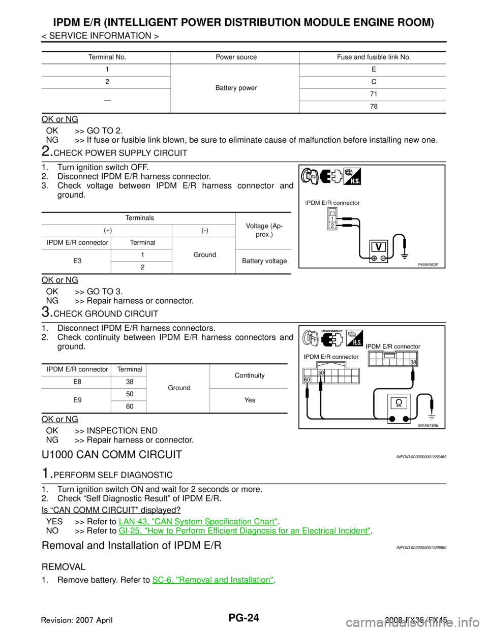
2.CHECK POWER SUPPLY CIRCUIT
1. Turn ignition switch OFF.
2. Disconnect IPDM E/R harness connector.
3. Check voltage between IPDM E/R harness connector and ground.
OK or NG
OK >> GO TO 3.
NG >> Repair harness or connector.
3.CHECK GROUND CIRCUIT
1. Disconnect IPDM E/R harness connectors.
2. Check continuity between IPDM E/R harness connectors and ground.
OK or NG
OK >> INSPECTION END
NG >> Repair harness or connector.
U1000 CAN COMM CIRCUITINFOID:0000000001366489
1.PERFORM SELF DIAGNOSTIC
1. Turn ignition switch ON and wait for 2 seconds or more.
2. Check “Self Diagnostic Result” of IPDM E/R.
Is
“CAN COMM CIRCUIT” displayed?
YES >> Refer to LAN-43, "CAN System Specification Chart".
NO >> Refer to GI-25, "
How to Perform Efficient Diagnosis for an Electrical Incident".
Removal and Installation of IPDM E/RINFOID:0000000001328880
REMOVAL
1. Remove battery. Refer to SC-6, "Removal and Installation".
Terminal No. Power source Fuse and fusible link No.
1
Battery power E
2 C
— 71
78
Te r m i n a l s
Voltage (Ap-
prox.)
(+) (-)
IPDM E/R connector Terminal Ground
E3 1
Battery voltage
2
PKIB6562E
IPDM E/R connector Terminal
GroundContinuity
E8 38
E9 50
Ye s
60
SKIA6184E
3AA93ABC3ACD3AC03ACA3AC03AC63AC53A913A773A893A873A873A8E3A773A983AC73AC93AC03AC3
3A893A873A873A8F3A773A9D3AAF3A8A3A8C3A863A9D3AAF3A8B3A8C
Page 3530 of 3924

SUNROOFRF-15
< SERVICE INFORMATION >
C
DE
F
G H
J
K L
M A
B
RF
N
O P
Work FlowINFOID:0000000001328040
1. Check the symptom and customer's requests.
2. Understand the outline of system. Refer to RF-10, "
System Description".
3. According to the trouble diagnosis chart, repair or replace the cause of the malfunction. Refer to RF-15,
"Trouble Diagnosis Chart by Symptom".
4. Does sunroof system operate normally? If Yes, GO TO 5. If No, GO TO 3.
5. INSPECTION END.
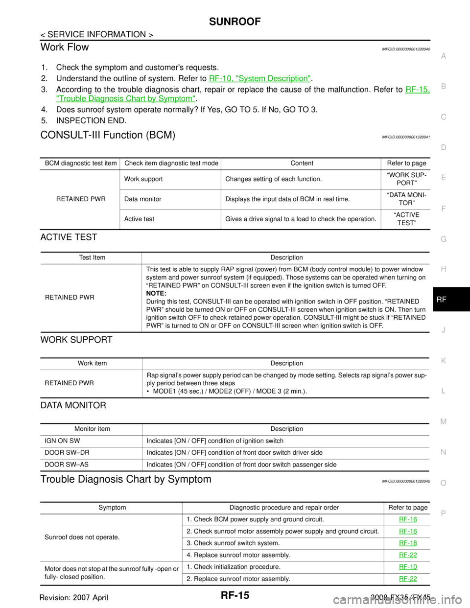
CONSULT-III Function (BCM)INFOID:0000000001328041
ACTIVE TEST
WORK SUPPORT
DATA MONITOR
Trouble Diagnosis Chart by SymptomINFOID:0000000001328042
BCM diagnostic test item Check item diagnostic test mode Content Refer to page
RETAINED PWR Work support Changes setting of each function.
“WORK SUP-
PORT”
Data monitor Displays the input data of BCM in real time. “DATA MONI-
TOR”
Active test Gives a drive signal to a load to check the operation. “ACTIVE
TEST”
Test Item Description
RETAINED PWR This test is able to supply RAP signal (powe
r) from BCM (body control module) to power window
system and power sunroof system (if equipped). Those systems can be operated when turning on
“RETAINED PWR” on CONSULT-III screen even if the ignition switch is turned OFF.
NOTE:
During this test, CONSULT-III can be operated with ignition switch in OFF position. “RETAINED
PWR” should be turned ON or OFF on CONSULT-III screen when ignition switch is ON. Then turn
ignition switch OFF to check retained power operation. CONSULT-III might be stuck if “RETAINED
PWR” is turned to ON or OFF on CONSULT- III screen when ignition switch is OFF.
Work item Description
RETAINED PWR Rap signal’s power supply period can be changed by mode setting. Selects rap signal’s power sup-
ply period between three steps
MODE1 (45 sec.) / MODE2 (OFF) / MODE 3 (2 min.).
Monitor item Description
IGN ON SW Indicates [ON / OFF] condition of ignition switch
DOOR SW–DR Indicates [ON / OFF] condition of front door switch driver side
DOOR SW–AS Indicates [ON / OFF] condition of front door switch passenger side
Symptom Diagnostic procedure and repair order Refer to page
Sunroof does not operate. 1. Check BCM power supply and ground circuit.
RF-16
2. Check sunroof motor assembly power supply and ground circuit.RF-16
3. Check sunroof switch system. RF-18
4. Replace sunroof motor assembly.RF-22
Motor does not stop at the sunroof fully -open or
fully- closed position.1. Check initialization procedure.
RF-10
2. Replace sunroof motor assembly.RF-22
3AA93ABC3ACD3AC03ACA3AC03AC63AC53A913A773A893A873A873A8E3A773A983AC73AC93AC03AC3
3A893A873A873A8F3A773A9D3AAF3A8A3A8C3A863A9D3AAF3A8B3A8C
Page 3586 of 3924

REAR SUSPENSION ASSEMBLYRSU-5
< SERVICE INFORMATION >
C
DF
G H
I
J
K L
M A
B
RSU
N
O P
REAR SUSPENSION ASSEMBLY
On-Vehicle Inspection and ServiceINFOID:0000000001327552
Make sure the mounting conditions (looseness, ba ck lash) of each component and component status (wear,
damage) are normal.
INSPECTION OF BALL JOINT END PLAY
Measure axial end play by installing and moving up/down with an
iron pry bar or something similar between suspension arm and axle.
CAUTION:
Be careful not to damage ball joint boot.
SHOCK ABSORBER INSPECTION
Check shock absorber for oil leakage, damage and replace if necessary.
Wheel AlignmentInspectionINFOID:0000000001327553
DESCRIPTION
Measure wheel alignment under unladen conditions. “U nladen conditions” means that fuel, engine coolant,
and lubricant are full. Spare tire, jack, hand tools and mats in designated positions.
PRELIMINARY INSPECTION
Check tires for improper air pressure and wear.
Check road wheels for runout.
Check wheel bearing axial end play.
Check ball joint axial end play of suspension arm.
Check shock absorber operation.
Check each mounting point of axle and suspension for looseness and deformation.
Check each link, arm and member for cracks, deformation, and other damage.
Check vehicle posture.
GENERAL INFORMATION AND RECOMMENDATIONS
A four-wheel thrust alignment should be performed.
- This type of alignment is recomm ended for any NISSAN/INFINITI vehicle.
- The four-wheel “thrust” process helps ensure that t he vehicle is properly aligned and the steering wheel is
centered.
- The alignment rack itself should be capable of accepting any NISSAN/INFINITI vehicle.
- The rack should be checked to ensure that it is level.
Make sure the machine is properly calibrated.
- Your alignment equipment should be regularly ca librated in order to give correct information.
- Check with the manufacturer of your specific equi pment for their recommended Service/Calibration Sched-
ule.
THE ALIGNMENT PROCESS
IMPORTANT:
Use only the alignment specificati ons listed in this Service Manual.
When displaying the alignment settings, many alignment machines use “indicators”: (Green/red, plus or
minus, Go/No Go). Do NOT use these indicators.
- The alignment specifications programmed into your machine that operate these indicators may not be cor-
rect.
- This may result in an ERROR.
Some newer alignment machines are equipped with an optional “Rolling Compensation” method to “com-
pensate” the sensors (alignment targets or head units). DO NOT use this “Rolling Compensation”
method. Standard value
Axial end play : 0 mm (0 in)
SEIA0245J
3AA93ABC3ACD3AC03ACA3AC03AC63AC53A913A773A893A873A873A8E3A773A983AC73AC93AC03AC3
3A893A873A873A8F3A773A9D3AAF3A8A3A8C3A863A9D3AAF3A8B3A8C
Page 3642 of 3924

DTC INDEXSE-3
< SERVICE INFORMATION >
C
DE
F
G H
J
K L
M A
B
SE
N
O P
SERVICE INFORMATION
DTC INDEX
U1000INFOID:0000000001529390
B2112-B2128INFOID:0000000001529391
CONSULT display DTC detection condition Reference page
U1000: CAN COMM CIRCUIT When driver seat control unit is not transmitting or receiving
CAN communication signal for 2 seconds or more.
SE-42, "
Check CAN Com-
munication System"
CONSULT display DTC detection condition Reference page
B2112: SEAT SLIDE When any manual and automatic operations are not per-
formed, if any motor operations of seat slide is detected for
0.1 second or more, status is judged
“Output error”. SE-44, "
Check Sliding Mo-
tor Circuit"
SE-53, "Check Sliding Sen-
sor Circuit"
B2113: SEAT RECLINING
When any manual and automatic operations are not per-
formed, if any motor operations of seat reclining is detected
for 0.1 second or more, status is judged “Output error”. SE-45, "
Check Reclining
Motor Circuit"
SE-54, "Check Reclining
Sensor Circuit"
B2114: SEAT LIFTER FR
When any manual and automatic operations are not per-
formed, if any motor operations of seat lifting FR is detect-
ed for 0.1 second or more, status is judged “Output error”. SE-46, "
Check Front Lifting
Motor Circuit"
SE-55, "Check Front Lifting
Sensor Circuit"
B2115: SEAT LIFTER RR
When any manual and automatic operations are not per-
formed, if any motor operations of seat lifting RR is detect-
ed for 0.1 second or more, status is judged “Output error”. SE-47, "
Check Rear Lifting
Motor Circuit"
SE-56, "Check Rear Lifting
Sensor Circuit"
B 2 11 6 : T I LT O U T P U T
When any manual and automatic operations are not per-
formed, if any motor operations of steering tilt is detected
for 0.1 second or more, status is judged “Output error”. SE-49, "
Check Tilt Motor
Circuit"
SE-58, "Check Tilt Sensor
Circuit"
B2118: TILT SENSOR
When driver seat control unit detects 0.1V or lower, or 4.9V
or higher, from tilt sensor for 0.5 seconds or more. SE-58, "Check Tilt Sensor
Circuit"
B2119: TELESCO SENSOR
When driver seat control unit detects 0.1V or lower, or 4.9V
or higher, from
telescopic sensor for 0.5 seconds or more. SE-57, "Check Telescopic
Sensor Circuit"
B2125: P RANGE SWWith the A/T selector lever in P position (P range switch
ON), if the vehicle speed of 7 km/h (4 MPH) or higher was
input the detention switch input system is judged malfunc-
tioning. SE-74, "
Check A/T Device
(Park Position Switch) Cir-
cuit"
B2128: UART COMM Malfunction is detected in UART communication.
SE-80, "Check UART Com-
munication Line Circuit"
3AA93ABC3ACD3AC03ACA3AC03AC63AC53A913A773A893A873A873A8E3A773A983AC73AC93AC03AC3
3A893A873A873A8F3A773A9D3AAF3A8A3A8C3A863A9D3AAF3A8B3A8C
Page 3651 of 3924

SE-12
< SERVICE INFORMATION >
AUTOMATIC DRIVE POSITIONER
AUTOMATIC DRIVE POSITIONER
System DescriptionINFOID:0000000001328097
The system automatically moves the driver seat to facilitate entry/exit to/from the vehicle. The automatic
drive positioner control unit can also store the optimum driving positions (driver seat, steering wheel position
(tilt, telescopic) and door mirror position) for 2 people. If the driver is changes, one-touch operation allows
changing to the other driving position.
The settings (ON/OFF) of the automatic sliding s eat (Entry/Exiting operation) at entry/exit can be changed
as desired, using the display unit in the center of the instrument panel. The set content is transmitted by
CAN communication, from display contro l unit to driver seat control unit.
Using CONSULT-III, the seat slide and steering wheel amount at entry/exit setting can be changed.
MANUAL OPERATION
The driving position [seat position, steering wheel posit ion (tilt, telescopic) and door mirror position] can be
adjusted with the power seat switch or ADP steering switch or door mirror remote control switch.
NOTE:
The seat can be manually operated with the ignition switch OFF.
The door mirrors can be manually operated with the ignition switch turned ACC or ON.
AUTOMATIC OPERATION
NOTE:
Disconnecting the battery erases the stored memory.
After connecting the battery, insert the key into the ignition cylinder and turn the driver door switch ON (open) →OFF (close) →ON
(open), the Entry/ Exiting operation becomes possible.
After exiting operation is carried out, return operation can be operated.
NOTE:
During automatic operation, if the ignition switch is turned ON →START, the automatic operation is suspended. When the ignition switch
returns to ON, it resumes.
MEMORY STORING AND KEYFOB INTERLOCK STORING
Store the 2 driving positions and shifts to t he stored driving position with the memory switch.
Function Description
Memory switch operation The seat, steering and door mirror move to the stored driving position by pushing
memory switch (1 or 2).
Entry/Exiting function Exiting operation At exit, the seat moves backward and steering wheel moves forward/upward.
Entry operation
At entry, the seat and steering wheel returns from the exiting position to the previous
driving position.
keyfob interlock operation Perform memory operation, exiting operation and entry operation by pressing keyfob
unlock button.
Auto operation temporary stop
conditions. When ignition switch turned to START during memory switch operation and return opera-
tion, memory switch operation and entry operation is stopped.
Auto operation stop conditions. When the vehicle speed becomes 7 km/h (4 MPH) or higher.
When the setting switch, memory switch 1, or 2 are pressed.
When A/T selector lever is in any position other than P.
When the door mirror remote control switch is operated (when ignition switch turned to
ON or ACC).
When power seat switch turned ON.
When ADP steering switch turned ON (telescopic operation or tilt operation).
When door mirror operates (only memory switch operation).
When driver seat sliding Entry/Exiting setting is OFF (only entry/exiting operation).
When steering wheel tilt and telescopic Entry/Exiting setting is OFF (only entry/exiting op-
eration).
When the tilt and telescopic sensor malfunction is detected.
3AA93ABC3ACD3AC03ACA3AC03AC63AC53A913A773A893A873A873A8E3A773A983AC73AC93AC03AC3
3A893A873A873A8F3A773A9D3AAF3A8A3A8C3A863A9D3AAF3A8B3A8C