Lighting System INFINITI FX35 2008 Manual Online
[x] Cancel search | Manufacturer: INFINITI, Model Year: 2008, Model line: FX35, Model: INFINITI FX35 2008Pages: 3924, PDF Size: 81.37 MB
Page 3272 of 3924

LT-170
< SERVICE INFORMATION >
ILLUMINATION
to A/C and AV switch (illumination) terminal 3
to DVD player (illumination) terminal 12
to coin box illumination terminal 2 and
to rear power window switch LH and RH (illumination) terminals 6,
through combination switch (spiral cable) terminal 18
to audio steering switch (illumination)
to icc steering switch (illumination) (with icc) and
to ascd steering switch (illumination) (without icc)
Illumination control
through combination meter terminal 19
to A/T device (illumination) terminal 12
to snow mode switch (illumination) terminal 6
to VDC off switch (illumination) terminal 4
to clock (illumination) terminal 4
to hazard switch (illumination) terminal 4
to heated seat switch (driver side) (illumination) terminal 6
to heated seat switch (passenger side) (illumination) terminal 6
to door mirror remote control switch terminal 15
to LDW switch (illumination) terminal 4,
to combination switch (spiral cable) terminal 27
to A/C and AV switch (illumination) terminal 4 and
to DVD player (illumination) terminal 10,
through combination switch (spiral cable) terminal 21
to audio steering switch (illumination)
to icc steering switch (illumination) (with icc) and
to ascd steering switch (illumination) (without icc)
Ground is supplied at all times
to glove box lamp terminal 2 and
to coin box illumination terminal 3
through grounds M35, M45 and M85,
to rear power window switch LH and RH (illumination) terminals 7
through grounds B15 and B45.
With power and ground supplied, illumination lamps illuminate.
EXTERIOR LAMP BATTERY SAVER CONTROL
When the lighting switch is in the 1ST or 2ND position (or if auto light system is activated), and ignition switch
is turned from ON or ACC to OFF, batte ry saver control function is activated.
Under this condition, illumination lamps remain illuminated for 5 minutes, then illumination lamps are turned
off.
When the lighting switch is turned from OFF to 1ST or 2 ND position (or if auto light system is activated) after
illumination lamps are turned off by battery save r control, and illumination lamps illuminate again.
Exterior lamp battery saver control mode can be changed by the function setting of CONSULT-III.
CAN Communication System DescriptionINFOID:0000000001328423
CAN (Controller Area Network) is a serial communication line for real time application. It is an on-vehicle mul-
tiplex communication line with high data communication s peed and excellent error detection ability. Many elec-
tronic control units are equipped onto a vehicle, and each control unit shares information and links with other
control units during operation (not independent). In CA N communication, control units are connected with 2
communication lines (CAN H line, CAN L line) allowing a high rate of information transmission with less wiring.
Each control unit transmits/receives data but selectively reads required data only.
CAN Communication UnitINFOID:0000000001328424
Refer to LAN-43, "CAN System Specification Chart".
3AA93ABC3ACD3AC03ACA3AC03AC63AC53A913A773A893A873A873A8E3A773A983AC73AC93AC03AC3
3A893A873A873A8F3A773A9D3AAF3A8A3A8C3A863A9D3AAF3A8B3A8C
Page 3885 of 3924

WW-10
< SERVICE INFORMATION >
FRONT WIPER AND WASHER SYSTEM
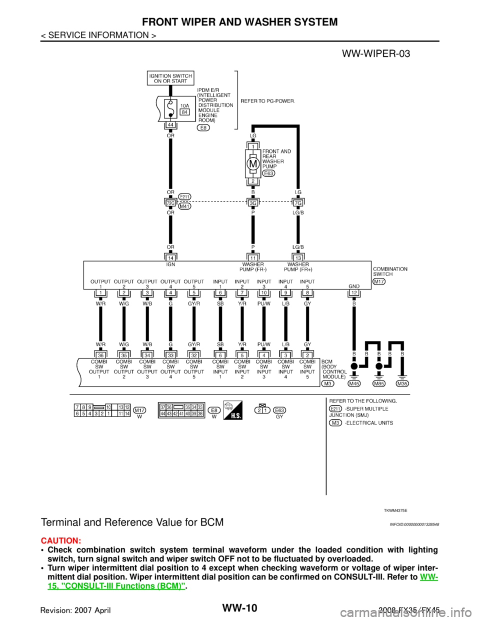
Terminal and Reference Value for BCM
INFOID:0000000001328548
CAUTION:
Check combination switch system terminal waveform under the loaded condition with lighting
switch, turn signal switch and wiper switch OFF not to be fluctuated by overloaded.
Turn wiper intermittent dial posi tion to 4 except when checking wavef orm or voltage of wiper inter-
mittent dial position. Wiper intermittent dial position can be confirmed on CONSULT-III. Refer to WW-
15, "CONSULT-III Functions (BCM)".
TKWM4375E
3AA93ABC3ACD3AC03ACA3AC03AC63AC53A913A773A893A873A873A8E3A773A983AC73AC93AC03AC3
3A893A873A873A8F3A773A9D3AAF3A8A3A8C3A863A9D3AAF3A8B3A8C
Page 3886 of 3924

FRONT WIPER AND WASHER SYSTEMWW-11
< SERVICE INFORMATION >
C
DE
F
G H
I
J
L
M A
B
WW
N
O P
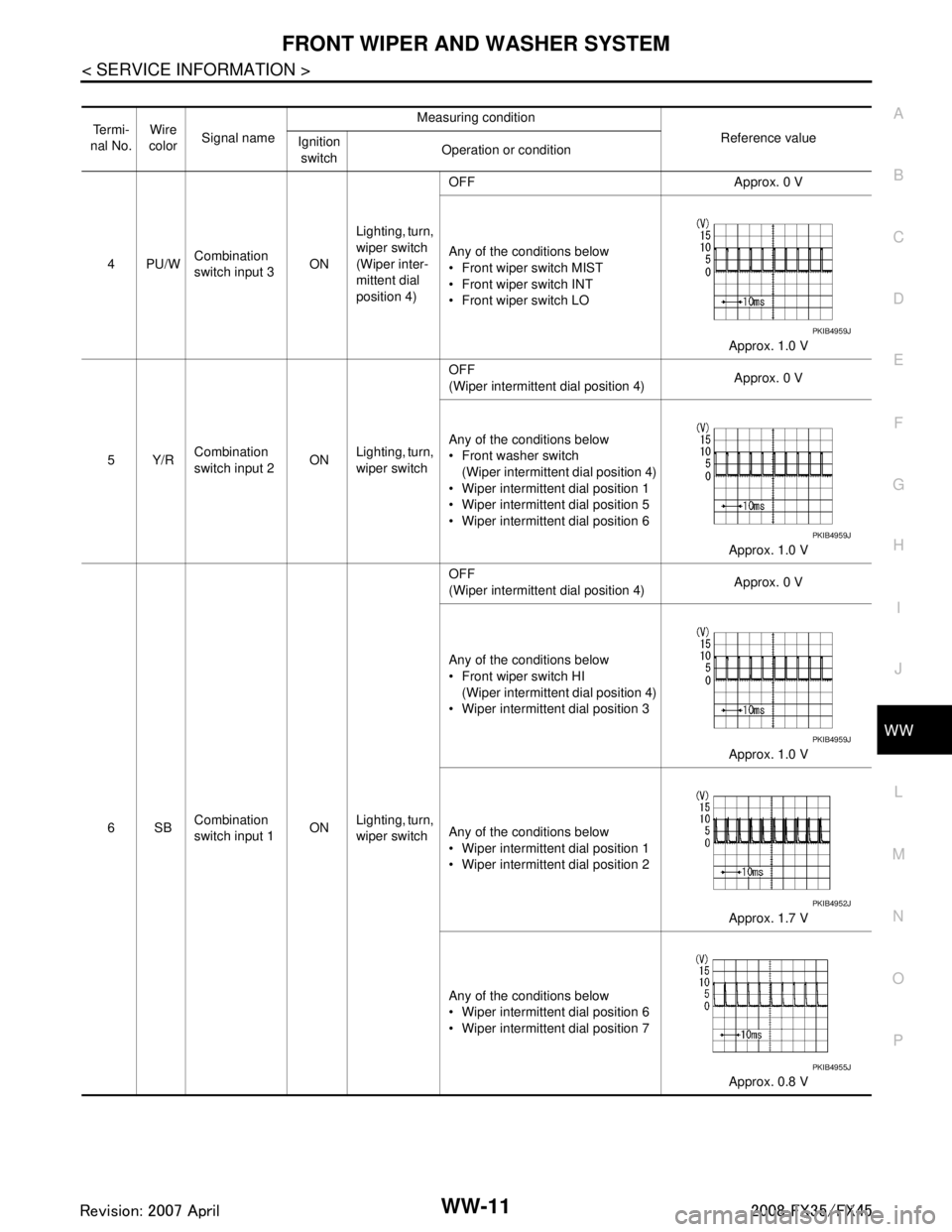
Te r m i -
nal No. Wire
color Signal name Measuring condition
Reference value
Ignition
switch Operation or condition
4PU/W Combination
switch input 3
ONLighting, turn,
wiper switch
(Wiper inter-
mittent dial
position 4) OFF Approx. 0 V
Any of the conditions below
Front wiper switch MIST
Front wiper switch INT
Front wiper switch LO
Approx. 1.0 V
5Y/R Combination
switch input 2 ON
Lighting, turn,
wiper switch OFF
(Wiper intermittent dial position 4)
Approx. 0 V
Any of the conditions below
Front washer switch (Wiper intermittent dial position 4)
Wiper intermittent dial position 1
Wiper intermittent dial position 5
Wiper intermittent dial position 6
Approx. 1.0 V
6SB Combination
switch input 1 ON
Lighting, turn,
wiper switch OFF
(Wiper intermittent dial position 4)
Approx. 0 V
Any of the conditions below
Front wiper switch HI (Wiper intermittent dial position 4)
Wiper intermittent dial position 3
Approx. 1.0 V
Any of the conditions below
Wiper intermittent dial position 1
Wiper intermittent dial position 2 Approx. 1.7 V
Any of the conditions below
Wiper intermittent dial position 6
Wiper intermittent dial position 7 Approx. 0.8 V
PKIB4959J
PKIB4959J
PKIB4959J
PKIB4952J
PKIB4955J
3AA93ABC3ACD3AC03ACA3AC03AC63AC53A913A773A893A873A873A8E3A773A983AC73AC93AC03AC3
3A893A873A873A8F3A773A9D3AAF3A8A3A8C3A863A9D3AAF3A8B3A8C
Page 3887 of 3924

WW-12
< SERVICE INFORMATION >
FRONT WIPER AND WASHER SYSTEM
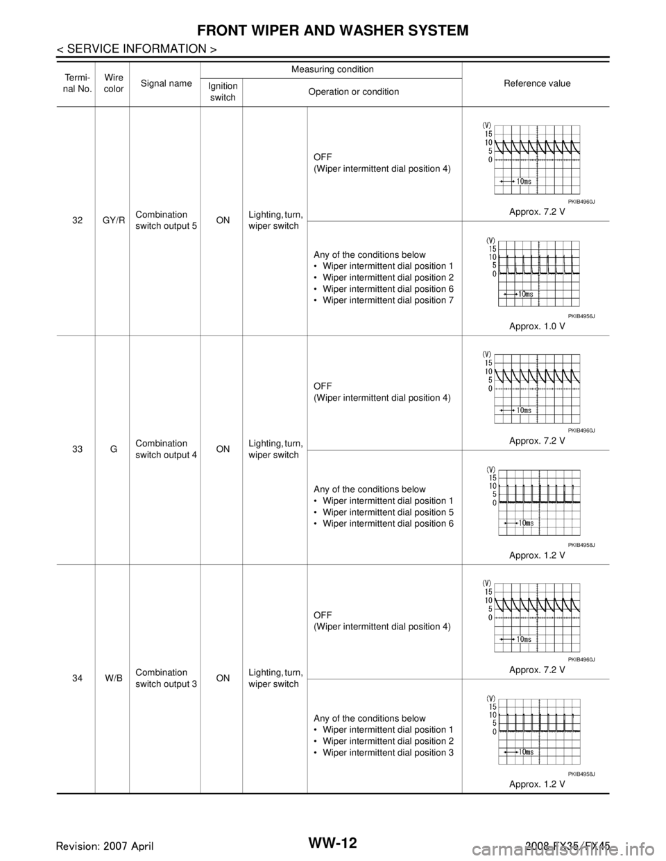
32 GY/RCombination
switch output 5 ON
Lighting, turn,
wiper switch OFF
(Wiper intermittent dial position 4)
Approx. 7.2 V
Any of the conditions below
Wiper intermittent dial position 1
Wiper intermittent dial position 2
Wiper intermittent dial position 6
Wiper intermittent dial position 7 Approx. 1.0 V
33 G Combination
switch output 4
ONLighting, turn,
wiper switch OFF
(Wiper intermittent dial position 4)
Approx. 7.2 V
Any of the conditions below
Wiper intermittent dial position 1
Wiper intermittent dial position 5
Wiper intermittent dial position 6 Approx. 1.2 V
34 W/B Combination
switch output 3 ONLighting, turn,
wiper switch OFF
(Wiper intermittent dial position 4)
Approx. 7.2 V
Any of the conditions below
Wiper intermittent dial position 1
Wiper intermittent dial position 2
Wiper intermittent dial position 3 Approx. 1.2 V
Te r m i -
nal No. Wire
color Signal name Measuring condition
Reference value
Ignition
switch Operation or condition
PKIB4960J
PKIB4956J
PKIB4960J
PKIB4958J
PKIB4960J
PKIB4958J
3AA93ABC3ACD3AC03ACA3AC03AC63AC53A913A773A893A873A873A8E3A773A983AC73AC93AC03AC3
3A893A873A873A8F3A773A9D3AAF3A8A3A8C3A863A9D3AAF3A8B3A8C
Page 3888 of 3924

FRONT WIPER AND WASHER SYSTEMWW-13
< SERVICE INFORMATION >
C
DE
F
G H
I
J
L
M A
B
WW
N
O P
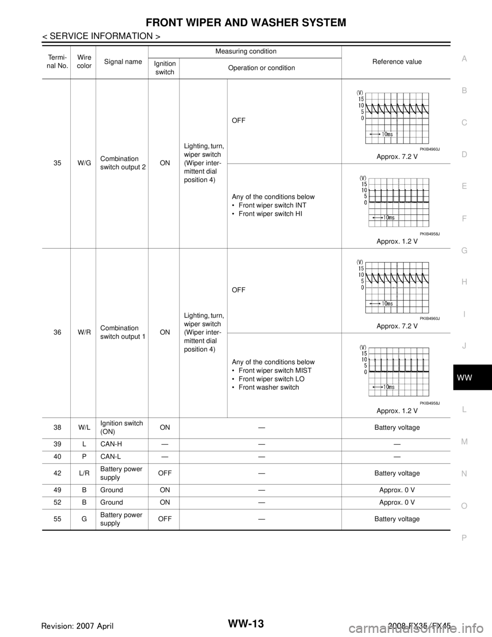
35 W/G Combination
switch output 2 ONLighting, turn,
wiper switch
(Wiper inter-
mittent dial
position 4) OFF
Approx. 7.2 V
Any of the conditions below
Front wiper switch INT
Front wiper switch HI Approx. 1.2 V
36 W/R Combination
switch output 1
ONLighting, turn,
wiper switch
(Wiper inter-
mittent dial
position 4) OFF
Approx. 7.2 V
Any of the conditions below
Front wiper switch MIST
Front wiper switch LO
Front washer switch Approx. 1.2 V
38 W/L Ignition switch
(ON) ON — Battery voltage
39 L CAN-H — — —
40 P CAN-L — — —
42 L/R Battery power
supply
OFF — Battery voltage
49 B Ground ON — Approx. 0 V
52 B Ground ON — Approx. 0 V
55 G Battery power
supply OFF — Battery voltage
Te r m i -
nal No. Wire
color Signal name Measuring condition
Reference value
Ignition
switch Operation or condition
PKIB4960J
PKIB4958J
PKIB4960J
PKIB4958J
3AA93ABC3ACD3AC03ACA3AC03AC63AC53A913A773A893A873A873A8E3A773A983AC73AC93AC03AC3
3A893A873A873A8F3A773A9D3AAF3A8A3A8C3A863A9D3AAF3A8B3A8C
Page 3908 of 3924

REAR WIPER AND WASHER SYSTEMWW-33
< SERVICE INFORMATION >
C
DE
F
G H
I
J
L
M A
B
WW
N
O P
Terminal and Reference Value for BCMINFOID:0000000001328579
CAUTION:
Check combination switch system terminal wavef orm under the loaded condition with lighting
switch, turn signal switch an d wiper switch OFF not to be fluctuated by overloaded.
Turn wiper intermittent dial position to 4 except when checking waveform or voltage of wiper inter-
mittent dial position. Wiper intermittent dial position can be confirmed on CONSULT-III. Refer to WW-
15, "CONSULT-III Functions (BCM)".
TKWM4377E
3AA93ABC3ACD3AC03ACA3AC03AC63AC53A913A773A893A873A873A8E3A773A983AC73AC93AC03AC3
3A893A873A873A8F3A773A9D3AAF3A8A3A8C3A863A9D3AAF3A8B3A8C
Page 3909 of 3924

WW-34
< SERVICE INFORMATION >
REAR WIPER AND WASHER SYSTEM
Te r m i n a l No. Wire
color Signal name Measuring condition
Reference value
Ignition
switch Operation or condition
5Y/R Combination
switch input 2 ONLighting, turn, wip-
er switch
(Wiper intermittent
dial position 4) OFF Approx. 0 V
Rear washer switch
Approx. 1.0 V
Rear wiper switch ON Approx. 0.8 v
6SB Combination
switch input 1 ONLighting, turn,
wiper switch
(Wiper intermittent
dial position 4) OFF Approx. 0 V
Rear wiper INT
Approx. 1.0 V
32 GY/R Combination
switch output 5
ONLighting, turn,
wiper switch
(Wiper intermittent
dial position 4) OFF
Approx. 7.0 - 7.5 V
Rear wiper ON Approx. 1.0 V
PKIB4959J
PKIB4955J
PKIB4959J
PKIB4960J
PKIB4956J
3AA93ABC3ACD3AC03ACA3AC03AC63AC53A913A773A893A873A873A8E3A773A983AC73AC93AC03AC3
3A893A873A873A8F3A773A9D3AAF3A8A3A8C3A863A9D3AAF3A8B3A8C
Page 3910 of 3924

REAR WIPER AND WASHER SYSTEMWW-35
< SERVICE INFORMATION >
C
DE
F
G H
I
J
L
M A
B
WW
N
O P
How to Proceed with Trouble DiagnosisINFOID:0000000001328580
1. Confirm the symptoms and customer complaint.
33 G Combination
switch output 4 ONLighting, turn, wip-
er switch
(Wiper intermittent
dial position 4) OFF
Approx. 7.2 V
Rear wiper switch INT Approx. 1.2 V
34 W/B Combination
switch output 3
ONLighting, turn, wip-
er switch
(Wiper intermittent
dial position 4) OFF
Approx. 7.2 V
Rear washer switch Approx. 1.2 V
38 W/L Ignition switch
(ON) ON — Battery voltage
39 L CAN − H— — —
40 P CAN − L— — —
42 L/R Battery power
supply
OFF — Battery voltage
49 B Ground ON — Approx. 0 V
52 B Ground ON — Approx. 0 V
55 G Battery power
supply OFF — Battery voltage
59 Y Rear wiper auto
stop signal
ONWiper operating Approx. 0 V
Wiper stopped Battery voltage
70 SB Rear wiper mo-
tor output signal ON Wiper switch OFF Approx. 0 V
ON Battery voltage
Te r m i n a l
No. Wire
color Signal name Measuring condition
Reference value
Ignition
switch Operation or condition
PKIB4960J
PKIB4958J
PKIB4960J
PKIB4958J
3AA93ABC3ACD3AC03ACA3AC03AC63AC53A913A773A893A873A873A8E3A773A983AC73AC93AC03AC3
3A893A873A873A8F3A773A9D3AAF3A8A3A8C3A863A9D3AAF3A8B3A8C