3000 INFINITI FX35 2008 Service Manual
[x] Cancel search | Manufacturer: INFINITI, Model Year: 2008, Model line: FX35, Model: INFINITI FX35 2008Pages: 3924, PDF Size: 81.37 MB
Page 82 of 3924
PREPARATIONAT-9
< SERVICE INFORMATION >
DE
F
G H
I
J
K L
M A
B
AT
N
O P
PREPARATION
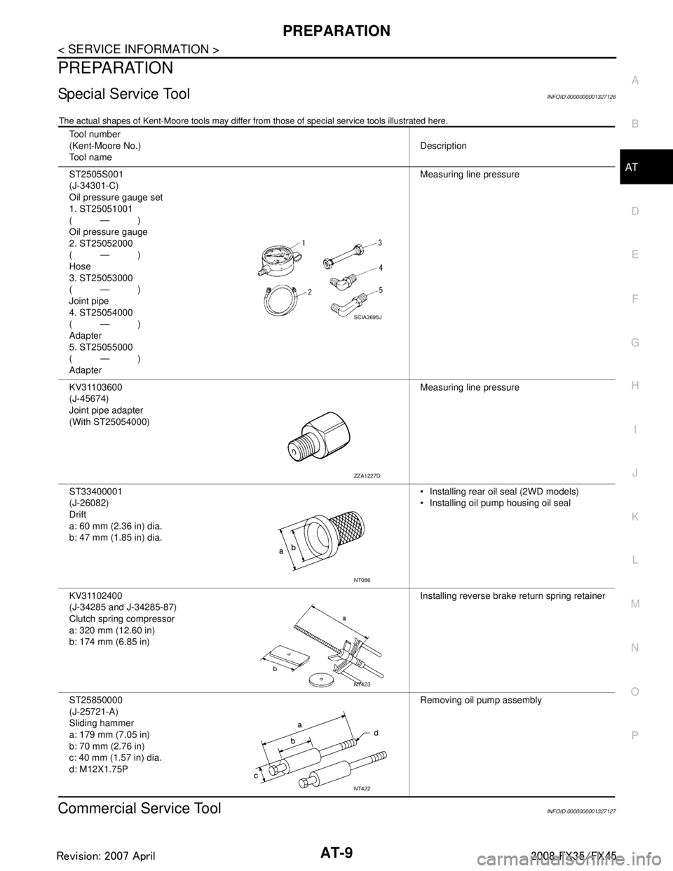
Special Service ToolINFOID:0000000001327126
The actual shapes of Kent-Moore t ools may differ from those of special service tools illustrated here.
Commercial Service ToolINFOID:0000000001327127
Tool number
(Kent-Moore No.)
Tool name Description
ST2505S001
(J-34301-C)
Oil pressure gauge set
1. ST25051001
(—)
Oil pressure gauge
2. ST25052000
(—)
Hose
3. ST25053000
(—)
Joint pipe
4. ST25054000
(—)
Adapter
5. ST25055000
(—)
Adapter Measuring line pressure
KV31103600
(J-45674)
Joint pipe adapter
(With ST25054000) Measuring line pressure
ST33400001
(J-26082)
Drift
a: 60 mm (2.36 in) dia.
b: 47 mm (1.85 in) dia. Installing rear oil seal (2WD models)
Installing oil pump housing oil seal
KV31102400
(J-34285 and J-34285-87)
Clutch spring compressor
a: 320 mm (12.60 in)
b: 174 mm (6.85 in) Installing reverse brake
return spring retainer
ST25850000
(J-25721-A)
Sliding hammer
a: 179 mm (7.05 in)
b: 70 mm (2.76 in)
c: 40 mm (1.57 in) dia.
d: M12X1.75P Removing oil pump assembly
SCIA3695J
ZZA1227D
NT086
NT423
NT422
3AA93ABC3ACD3AC03ACA3AC03AC63AC53A913A773A893A873A873A8E3A773A983AC73AC93AC03AC3
3A893A873A873A8F3A773A9D3AAF3A8A3A8C3A863A9D3AAF3A8B3A8C
Page 1022 of 3924
![INFINITI FX35 2008 Service Manual
PREPARATIONBRC-7
< SERVICE INFORMATION > [VDC/TCS/ABS]
C
D
E
G H
I
J
K L
M A
B
BRC
N
O P
PREPARATION
Special Service ToolINFOID:0000000001327656
The actual shapes of Kent-Moore tools may differ fr om](/img/42/57017/w960_57017-1021.png "INFINITI FX35 2008 Service Manual
PREPARATIONBRC-7
< SERVICE INFORMATION > [VDC/TCS/ABS]
C
D
E
G H
I
J
K L
M A
B
BRC
N
O P
PREPARATION
Special Service ToolINFOID:0000000001327656
The actual shapes of Kent-Moore tools may differ fr om")
PREPARATIONBRC-7
< SERVICE INFORMATION > [VDC/TCS/ABS]
C
D
E
G H
I
J
K L
M A
B
BRC
N
O P
PREPARATION
Special Service ToolINFOID:0000000001327656
The actual shapes of Kent-Moore tools may differ fr om those of special service tools illustrated here.
Commercial Service ToolINFOID:0000000001327657
Tool number
(Kent-Moore No.)
Tool name Description
ST30720000
(J-25405)
Drift
a: 77 mm (3.03 in) dia.
b: 55.5 mm (2.185 in) dia.
Installing rear sensor rotor
ST27863000
(—)
Drift
a: 74.5 mm (2.933 in) dia.
b: 62.5 mm (2.461 in) dia.
KV40104710
(—)
Drift
a: 76.3 mm (3.004 in) dia.
b: 67.9 mm (2.673 in) dia.
ZZA0701D
ZZA0832D
ZZA0832D
Tool name
Description
1: Flare nut crowfoot
a: 10 mm (0.39 in)/ 12 mm (0.47 in)
2: Torque wrench Installing brake tube
S-NT360
3AA93ABC3ACD3AC03ACA3AC03AC63AC53A913A773A893A873A873A8E3A773A983AC73AC93AC03AC3
3A893A873A873A8F3A773A9D3AAF3A8A3A8C3A863A9D3AAF3A8B3A8C
Page 1068 of 3924
![INFINITI FX35 2008 Service Manual
SENSOR ROTORBRC-53
< SERVICE INFORMATION > [VDC/TCS/ABS]
C
D
E
G H
I
J
K L
M A
B
BRC
N
O P
SENSOR ROTOR
Removal and InstallationINFOID:0000000001327699
REMOVAL
Front
Sensor rotor cannot be disassembl](/img/42/57017/w960_57017-1067.png "INFINITI FX35 2008 Service Manual
SENSOR ROTORBRC-53
< SERVICE INFORMATION > [VDC/TCS/ABS]
C
D
E
G H
I
J
K L
M A
B
BRC
N
O P
SENSOR ROTOR
Removal and InstallationINFOID:0000000001327699
REMOVAL
Front
Sensor rotor cannot be disassembl")
SENSOR ROTORBRC-53
< SERVICE INFORMATION > [VDC/TCS/ABS]
C
D
E
G H
I
J
K L
M A
B
BRC
N
O P
SENSOR ROTOR
Removal and InstallationINFOID:0000000001327699
REMOVAL
Front
Sensor rotor cannot be disassembled. To replace sensor rotor, replace wheel hub and bearing assembly.
Refer to FAX-4, "
Removal and Installation"(2WD models), FAX-11, "Removal and Installation"(AWD models).
Rear
Follow procedure below to remove rear sensor rotor.
- Remove side flange. Refer to RFD-14, "
Removal and Installation".
- Using a bearing replacer and puller, remove sensor rotor from side flange.
INSTALLATION
Front
Sensor rotor cannot be disassembled. To replace sensor rotor, replace wheel hub and bearing assembly.
Refer to FAX-4, "
Removal and Installation"(2WD models), FAX-11, "Removal and Installation"(AWD models).
Rear
Follow procedure below to install rear sensor rotor.
- Using a drifts, press rear sensor rotor onto side flange.
- Install side flange. Refer to RFD-14, "
Removal and Installation".
Tool number A: ST30720000 (J-25405)
B: ST27863000 ( — )
C: KV40104710 ( — )
SFIA3387E
3AA93ABC3ACD3AC03ACA3AC03AC63AC53A913A773A893A873A873A8E3A773A983AC73AC93AC03AC3
3A893A873A873A8F3A773A9D3AAF3A8A3A8C3A863A9D3AAF3A8B3A8C
Page 2493 of 3924
![INFINITI FX35 2008 Service Manual
PREPARATIONEM-9
< SERVICE INFORMATION > [VQ35DE]
C
D
E
F
G H
I
J
K L
M A
EM
NP
O
Commercial Service ToolINFOID:0000000001325701
KV10117700
(J44716)
Ring gear stopper
Removing and installing crankshaf](/img/42/57017/w960_57017-2492.png "INFINITI FX35 2008 Service Manual
PREPARATIONEM-9
< SERVICE INFORMATION > [VQ35DE]
C
D
E
F
G H
I
J
K L
M A
EM
NP
O
Commercial Service ToolINFOID:0000000001325701
KV10117700
(J44716)
Ring gear stopper
Removing and installing crankshaf")
PREPARATIONEM-9
< SERVICE INFORMATION > [VQ35DE]
C
D
E
F
G H
I
J
K L
M A
EM
NP
O
Commercial Service ToolINFOID:0000000001325701
KV10117700
(J44716)
Ring gear stopper
Removing and installing crankshaft pulley
10006 31U00
(—)
Engine rear slinger Removing and installing oil pan (upper) for on
vehicle service
—
(J-45488)
Quick connector release Removing fuel tube quick connectors in en-
gine room
Tool number
(Kent-Moore No.)
Tool name
Description
NT822
SBIA0530E
PBIC0198E
(Kent-Moore No.)
Tool name
Description
WS39930000
(—)
Tube presser Pressing the tube of liquid gasket
(—)
Power tool Loosening nuts and bolts
(BT3373-F)
Belt tension gauge Checking drive belt tension
NT052
PBIC0190E
AMA126
3AA93ABC3ACD3AC03ACA3AC03AC63AC53A913A773A893A873A873A8E3A773A983AC73AC93AC03AC3
3A893A873A873A8F3A773A9D3AAF3A8A3A8C3A863A9D3AAF3A8B3A8C
Page 2794 of 3924
PREPARATIONFFD-3
< SERVICE INFORMATION >
CEF
G H
I
J
K L
M A
B
FFD
N
O P
PREPARATION
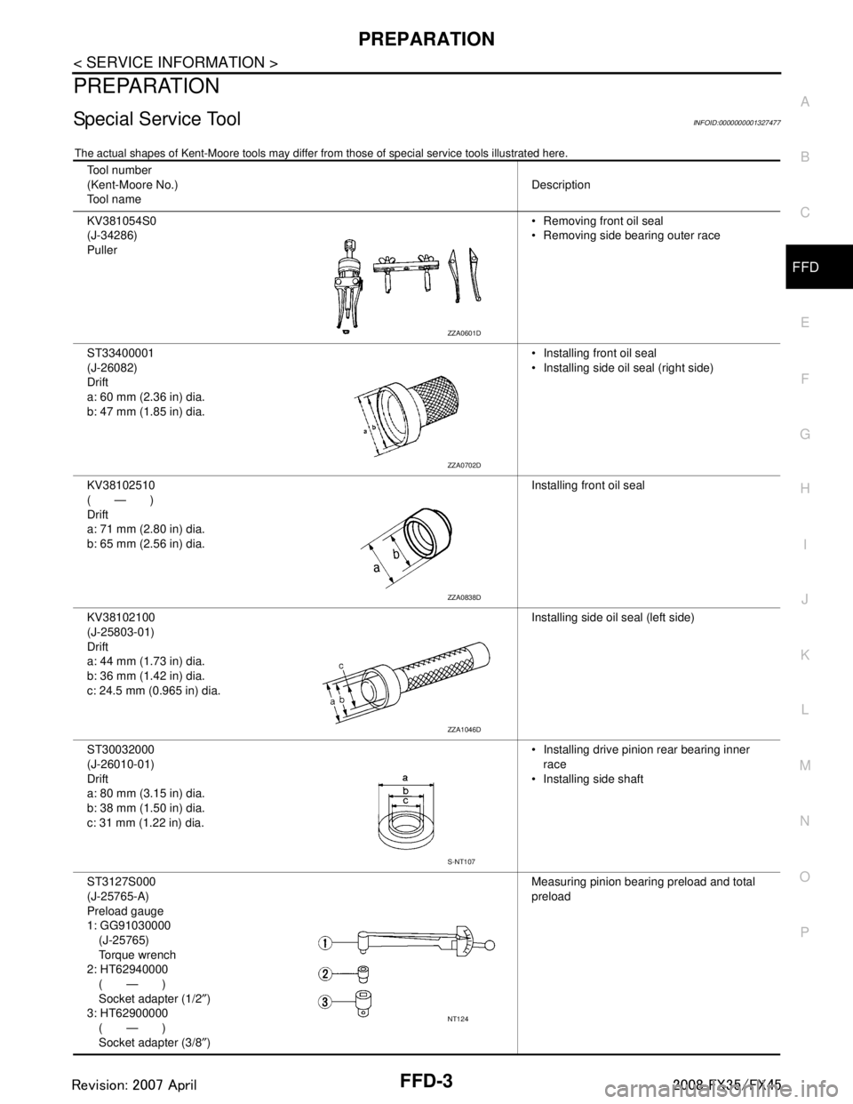
Special Service ToolINFOID:0000000001327477
The actual shapes of Kent-Moore t ools may differ from those of special service tools illustrated here.
Tool number
(Kent-Moore No.)
Tool name Description
KV381054S0
(J-34286)
Puller Removing front oil seal
Removing side bearing outer race
ST33400001
(J-26082)
Drift
a: 60 mm (2.36 in) dia.
b: 47 mm (1.85 in) dia. Installing front oil seal
Installing side oil seal (right side)
KV38102510
(—)
Drift
a: 71 mm (2.80 in) dia.
b: 65 mm (2.56 in) dia. Installing front oil seal
KV38102100
(J-25803-01)
Drift
a: 44 mm (1.73 in) dia.
b: 36 mm (1.42 in) dia.
c: 24.5 mm (0.965 in) dia. Installing side oil seal (left side)
ST30032000
(J-26010-01)
Drift
a: 80 mm (3.15 in) dia.
b: 38 mm (1.50 in) dia.
c: 31 mm (1.22 in) dia. Installing drive pinion rear bearing inner
race
Installing side shaft
ST3127S000
(J-25765-A)
Preload gauge
1: GG91030000 (J-25765)
Torque wrench
2: HT62940000 (—)
Socket adapter (1/2 ″)
3: HT62900000 (—)
Socket adapter (3/8 ″) Measuring pinion bearing preload and total
preload
ZZA0601D
ZZA0702D
ZZA0838D
ZZA1046D
S-NT107
NT124
3AA93ABC3ACD3AC03ACA3AC03AC63AC53A913A773A893A873A873A8E3A773A983AC73AC93AC03AC3
3A893A873A873A8F3A773A9D3AAF3A8A3A8C3A863A9D3AAF3A8B3A8C
Page 2795 of 3924
FFD-4
< SERVICE INFORMATION >
PREPARATION
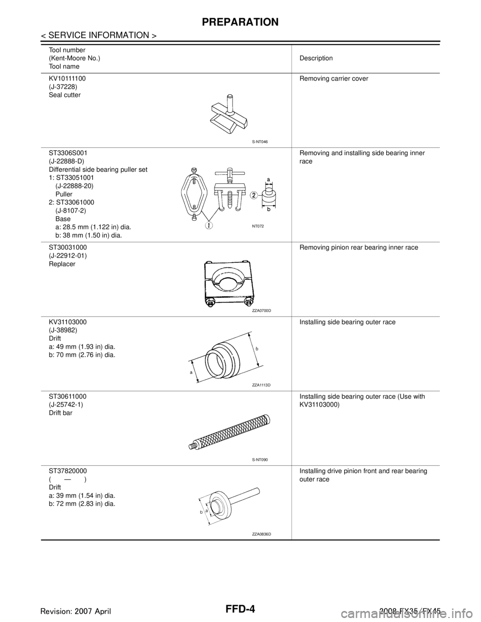
K V 1 0 1111 0 0
(J-37228)
Seal cutterRemoving carrier cover
ST3306S001
(J-22888-D)
Differential side bearing puller set
1: ST33051001 (J-22888-20)
Puller
2: ST33061000
(J-8107-2)
Base
a: 28.5 mm (1.122 in) dia.
b: 38 mm (1.50 in) dia. Removing and installing side bearing inner
race
ST30031000
(J-22912-01)
Replacer Removing pinion rear bearing inner race
KV31103000
(J-38982)
Drift
a: 49 mm (1.93 in) dia.
b: 70 mm (2.76 in) dia. Installing side bearing outer race
ST30611000
(J-25742-1)
Drift bar Installing side bearing outer race (Use with
KV31103000)
ST37820000
(—)
Drift
a: 39 mm (1.54 in) dia.
b: 72 mm (2.83 in) dia. Installing drive pinion front and rear bearing
outer race
Tool number
(Kent-Moore No.)
Tool name
Description
S-NT046
NT072
ZZA0700D
ZZA1113D
S-NT090
ZZA0836D
3AA93ABC3ACD3AC03ACA3AC03AC63AC53A913A773A893A873A873A8E3A773A983AC73AC93AC03AC3
3A893A873A873A8F3A773A9D3AAF3A8A3A8C3A863A9D3AAF3A8B3A8C
Page 2796 of 3924
PREPARATIONFFD-5
< SERVICE INFORMATION >
CEF
G H
I
J
K L
M A
B
FFD
N
O P
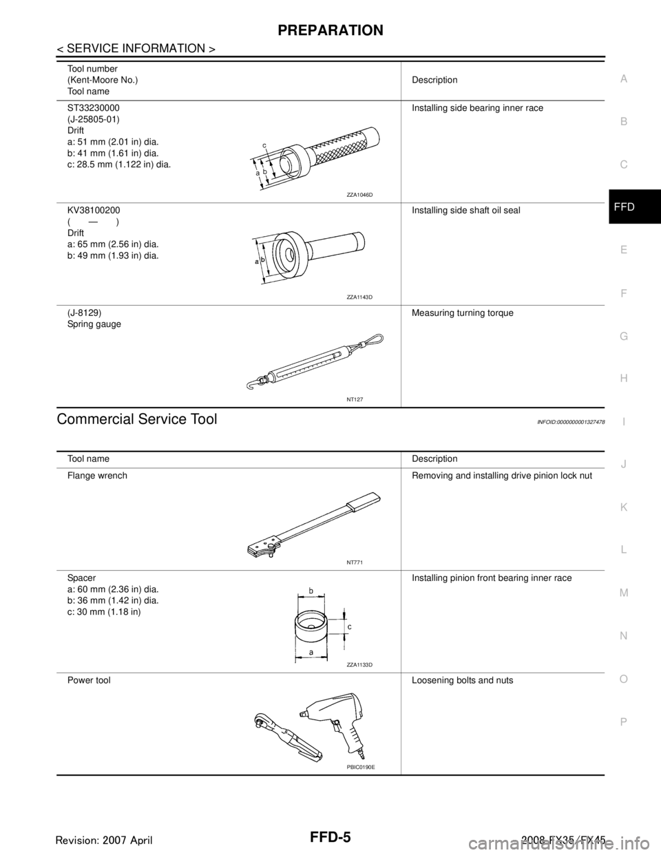
Commercial Service ToolINFOID:0000000001327478
ST33230000
(J-25805-01)
Drift
a: 51 mm (2.01 in) dia.
b: 41 mm (1.61 in) dia.
c: 28.5 mm (1.122 in) dia. Installing side bearing inner race
KV38100200
(—)
Drift
a: 65 mm (2.56 in) dia.
b: 49 mm (1.93 in) dia. Installing side shaft oil seal
(J-8129)
Spring gauge Measuring turning torque
Tool number
(Kent-Moore No.)
Tool name
Description
ZZA1046D
ZZA1143D
NT127
Tool name
Description
Flange wrench Removing and installing drive pinion lock nut
Spacer
a: 60 mm (2.36 in) dia.
b: 36 mm (1.42 in) dia.
c: 30 mm (1.18 in) Installing pinion front bearing inner race
Power tool Loosening bolts and nuts
NT771
ZZA1133D
PBIC0190E
3AA93ABC3ACD3AC03ACA3AC03AC63AC53A913A773A893A873A873A8E3A773A983AC73AC93AC03AC3
3A893A873A873A8F3A773A9D3AAF3A8A3A8C3A863A9D3AAF3A8B3A8C
Page 2820 of 3924
FRONT FINAL DRIVE ASSEMBLYFFD-29
< SERVICE INFORMATION >
CEF
G H
I
J
K L
M A
B
FFD
N
O P
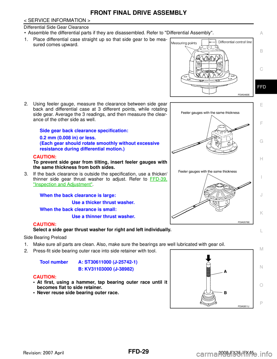
Differential Side Gear Clearance
Assemble the differential parts if they are disassembled. Refer to "Differential Assembly".
1. Place differential case straight up so that side gear to be mea-
sured comes upward.
2. Using feeler gauge, measure the clearance between side gear back and differential case at 3 different points, while rotating
side gear. Average the 3 readings, and then measure the clear-
ance of the other side as well.
CAUTION:
To prevent side gear from tilting, insert feeler gauges with
the same thickness from both sides.
3. If the back clearance is outside t he specification, use a thicker/
thinner side gear thrust washer to adjust. Refer to FFD-39,
"Inspection and Adjustment".
CAUTION:
Select a side gear thrust washer for right and left individually.
Side Bearing Preload
1. Make sure all parts are clean. Also, make sure the bearings are well lubricated with gear oil.
2. Press-fit side bearing outer race into side retainer with tool.
CAUTION:
At first, using a hammer, tap bearing outer race until itbecomes flat to side retainer.
Never reuse side bearing outer race.
PDIA0460E
Side gear back clearance specification:
0.2 mm (0.008 in) or less.
(Each gear should rotate smoothly without excessive
resistance during differential motion.)
When the back clearance is large:
Use a thicker thrust washer.
When the back clearance is small: Use a thinner thrust washer.
PDIA0576E
Tool number A: ST30611000 (J-25742-1) B: KV31103000 (J-38982)
PDIA0811J
3AA93ABC3ACD3AC03ACA3AC03AC63AC53A913A773A893A873A873A8E3A773A983AC73AC93AC03AC3
3A893A873A873A8F3A773A9D3AAF3A8A3A8C3A863A9D3AAF3A8B3A8C
Page 2821 of 3924
FFD-30
< SERVICE INFORMATION >
FRONT FINAL DRIVE ASSEMBLY
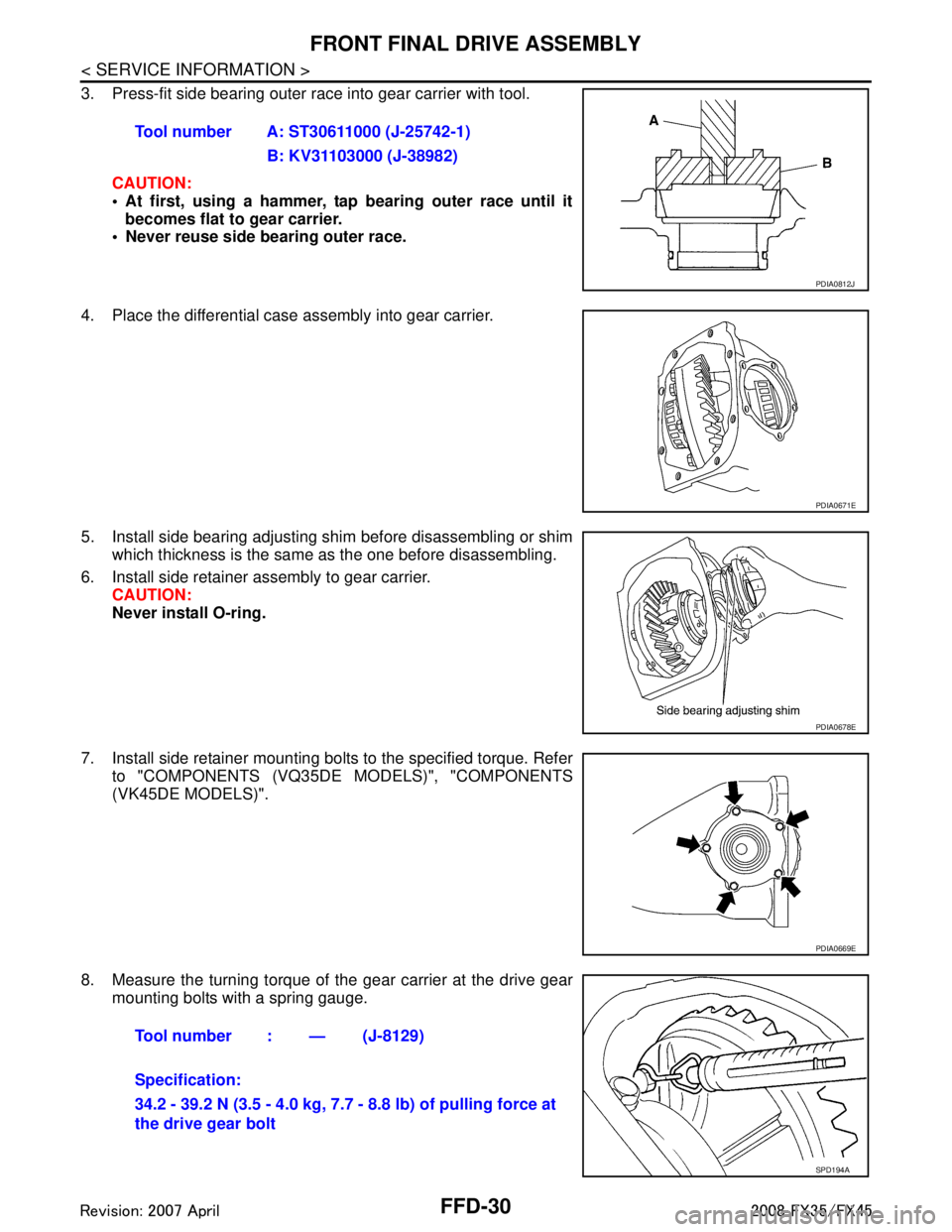
3. Press-fit side bearing outer race into gear carrier with tool.CAUTION:
At first, using a hammer, tap bearing outer race until itbecomes flat to gear carrier.
Never reuse side bearing outer race.
4. Place the differential case assembly into gear carrier.
5. Install side bearing adjusting shim before disassembling or shim which thickness is the same as the one before disassembling.
6. Install side retainer assembly to gear carrier. CAUTION:
Never install O-ring.
7. Install side retainer mounting bolts to the specified torque. Refer to "COMPONENTS (VQ35DE MODELS)", "COMPONENTS
(VK45DE MODELS)".
8. Measure the turning torque of the gear carrier at the drive gear
mounting bolts with a spring gauge. Tool number A: ST30611000 (J-25742-1)
B: KV31103000 (J-38982)
PDIA0812J
PDIA0671E
PDIA0678E
PDIA0669E
Tool number : — (J-8129)
Specification:
34.2 - 39.2 N (3.5 - 4.0 kg, 7.7 - 8.8 lb) of pulling force at
the drive gear bolt
SPD194A
3AA93ABC3ACD3AC03ACA3AC03AC63AC53A913A773A893A873A873A8E3A773A983AC73AC93AC03AC3
3A893A873A873A8F3A773A9D3AAF3A8A3A8C3A863A9D3AAF3A8B3A8C
Page 2827 of 3924
FFD-36
< SERVICE INFORMATION >
FRONT FINAL DRIVE ASSEMBLY
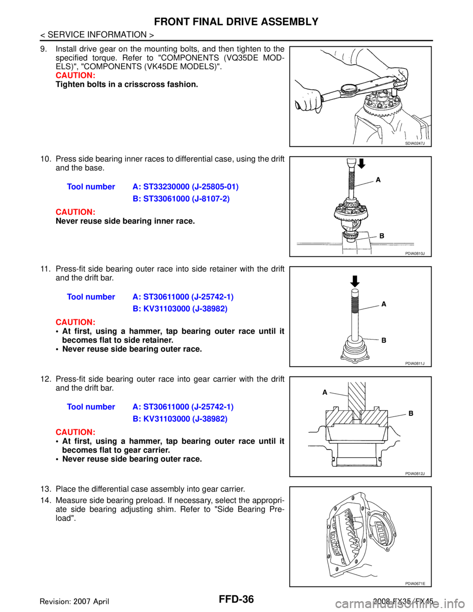
9. Install drive gear on the mounting bolts, and then tighten to thespecified torque. Refer to "COMPONENTS (VQ35DE MOD-
ELS)", "COMPONENTS (VK45DE MODELS)".
CAUTION:
Tighten bolts in a crisscross fashion.
10. Press side bearing inner races to differential case, using the drift and the base.
CAUTION:
Never reuse side bearing inner race.
11. Press-fit side bearing outer race into side retainer with the drift and the drift bar.
CAUTION:
At first, using a hammer, tap bearing outer race until itbecomes flat to side retainer.
Never reuse side bearing outer race.
12. Press-fit side bearing outer race into gear carrier with the drift and the drift bar.
CAUTION:
At first, using a hammer, tap bearing outer race until itbecomes flat to gear carrier.
Never reuse side bearing outer race.
13. Place the differential case assembly into gear carrier.
14. Measure side bearing preload. If necessary, select the appropri-
ate side bearing adjusting shim. Refer to "Side Bearing Pre-
load".
SDIA0247J
Tool number A: ST33230000 (J-25805-01)
B: ST33061000 (J-8107-2)
PDIA0810J
Tool number A: ST30611000 (J-25742-1)B: KV31103000 (J-38982)
PDIA0811J
Tool number A: ST30611000 (J-25742-1)B: KV31103000 (J-38982)
PDIA0812J
PDIA0671E
3AA93ABC3ACD3AC03ACA3AC03AC63AC53A913A773A893A873A873A8E3A773A983AC73AC93AC03AC3
3A893A873A873A8F3A773A9D3AAF3A8A3A8C3A863A9D3AAF3A8B3A8C